Hub for medical fiber connector devices
DeCastro, Jr. , et al.
U.S. patent number D887,993 [Application Number D/649,042] was granted by the patent office on 2020-06-23 for hub for medical fiber connector devices. This patent grant is currently assigned to Boston Scientific Scimed, Inc.. The grantee listed for this patent is Boston Scientific Scimed, Inc.. Invention is credited to Wen-Jui Ray Chia, Glenn DeCastro, Jr., Adam Nodiff, Steven Yihlih Peng.
| United States Patent | D887,993 |
| DeCastro, Jr. , et al. | June 23, 2020 |
Hub for medical fiber connector devices
Claims
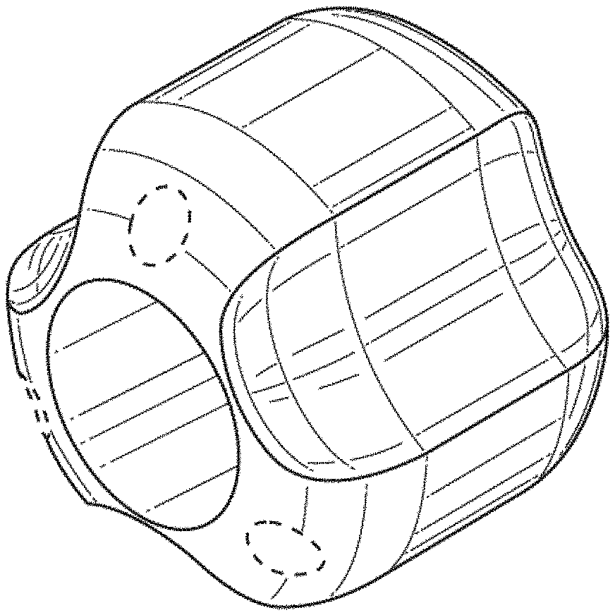
CLAIM We claim the ornamental design for a hub for medical fiber connector devices, as shown and described.
| Inventors: | DeCastro, Jr.; Glenn (Santa Clara, CA), Chia; Wen-Jui Ray (Sunnyvale, CA), Peng; Steven Yihlih (Fremont, CA), Nodiff; Adam (Southborough, MA) | ||||||||||
|---|---|---|---|---|---|---|---|---|---|---|---|
| Applicant: |
|
||||||||||
| Assignee: | Boston Scientific Scimed, Inc.
(Maple Grove, MN) |
||||||||||
| Appl. No.: | D/649,042 | ||||||||||
| Filed: | May 25, 2018 |
| Current U.S. Class: | D13/155 |
| Current International Class: | 1303 |
| Field of Search: | ;D13/133,146,147,151,153,154,155,156 ;D3/208 ;D8/349,382,394,396 ;D11/11,79 ;D19/203 ;D23/259,260,262 |
References Cited [Referenced By]
U.S. Patent Documents
| 6095956 | August 2000 | Huang |
| D451371 | December 2001 | Borotto |
| D577990 | October 2008 | Andre |
| D599299 | September 2009 | Parnapy |
| D629803 | December 2010 | St. Ives |
| D679581 | April 2013 | Liu |
| D701840 | April 2014 | Kazakia |
| D752955 | April 2016 | Rowan |
| D775937 | January 2017 | Davis |
| 9828724 | November 2017 | Kindstrand |
| D836561 | December 2018 | Hung |
| 2015/0096159 | April 2015 | Cawood |
| 2015/0233446 | August 2015 | Disantis |
Other References
|
The Pencil Grip Original Universal Ergonomic Writing Aid, The Pencil Grip, first available on Feb. 10, 2009 on amazon.com, retrieved on Jun. 2, 2019, retrieved from the Internet URL: https://www.amazon.com/Pencil-Grip-Universal-Ergonomic-TPG-11106/dp/B001S- N8HOY/ref=sr_1_4?keywords=pencil+gripper&qid=1559486344&s=gatewa. cited by examiner. |
Primary Examiner: Rivard; Jennifer
Assistant Examiner: Ofstun; Alison M
Attorney, Agent or Firm: Bookoff McAndrews, PLLC
Description
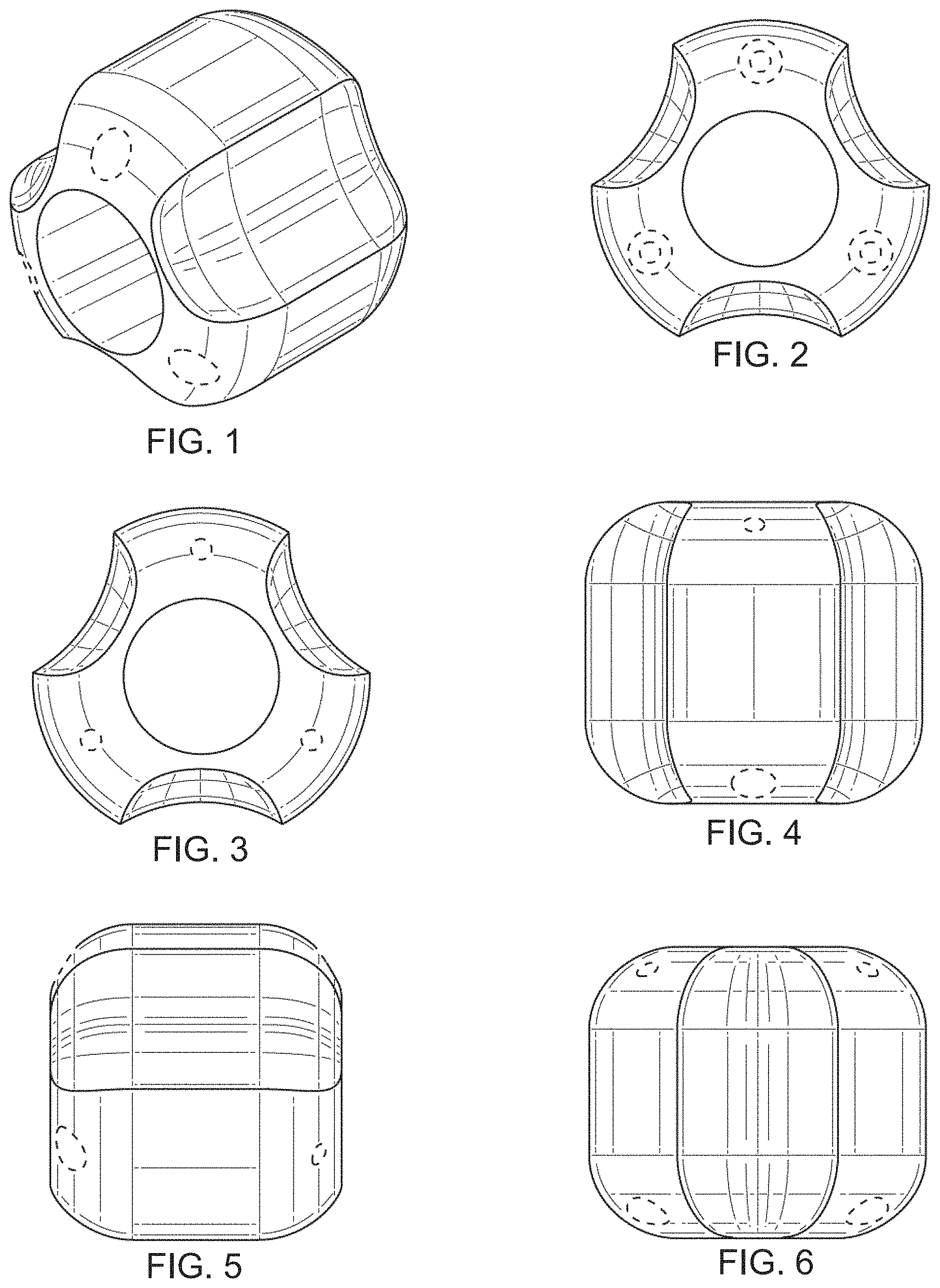
FIG. 1 is a perspective view of a hub for medical fiber connector devices, showing our new design;
FIG. 2 is a front view thereof;
FIG. 3 is a back view thereof;
FIG. 4 is a top view thereof;
FIG. 5 is a side view thereof, the opposite side being a mirror image thereof; and,
FIG. 6 is a bottom view thereof.
In the drawings, the broken lines represent portions of the article which form no part of the claimed design.
* * * * *
References
D00000
D00001
XML
uspto.report is an independent third-party trademark research tool that is not affiliated, endorsed, or sponsored by the United States Patent and Trademark Office (USPTO) or any other governmental organization. The information provided by uspto.report is based on publicly available data at the time of writing and is intended for informational purposes only.
While we strive to provide accurate and up-to-date information, we do not guarantee the accuracy, completeness, reliability, or suitability of the information displayed on this site. The use of this site is at your own risk. Any reliance you place on such information is therefore strictly at your own risk.
All official trademark data, including owner information, should be verified by visiting the official USPTO website at www.uspto.gov. This site is not intended to replace professional legal advice and should not be used as a substitute for consulting with a legal professional who is knowledgeable about trademark law.