Cap for a flow alarm device
Abdul-Hafiz , et al.
U.S. patent number D887,549 [Application Number D/662,935] was granted by the patent office on 2020-06-16 for cap for a flow alarm device. This patent grant is currently assigned to Masino Corporation. The grantee listed for this patent is MASIMO CORPORATION. Invention is credited to Yassir Kamel Abdul-Hafiz, Chad A. DeJong, Virginia Thanh Ta.


| United States Patent | D887,549 |
| Abdul-Hafiz , et al. | June 16, 2020 |
| **Please see images for: ( Certificate of Correction ) ** |
Cap for a flow alarm device
Claims
CLAIM The ornamental design for a cap for a flow alarm device, as shown and described.
| Inventors: | Abdul-Hafiz; Yassir Kamel (Irvine, CA), Ta; Virginia Thanh (Santa Ana, CA), DeJong; Chad A. (Los Angeles, CA) | ||||||||||
|---|---|---|---|---|---|---|---|---|---|---|---|
| Applicant: |
|
||||||||||
| Assignee: | Masino Corporation (Irvine,
CA) |
||||||||||
| Appl. No.: | D/662,935 | ||||||||||
| Filed: | September 10, 2018 |
| Current U.S. Class: | D24/129 |
| Current International Class: | 2402 |
| Field of Search: | ;D24/127-131,112-114,133,186 ;606/181,185 ;604/264,523-528,272,187,158,164.01-164.11,181,184,227 ;600/101,139,143 ;128/200.24,207.14,207.15 |
References Cited [Referenced By]
U.S. Patent Documents
| 3297255 | January 1967 | Fortman |
| 3595228 | July 1971 | Simon et al. |
| 4067329 | January 1978 | Winicki |
| 4316182 | February 1982 | Hodgson |
| 4669415 | June 1987 | Boord |
| D361380 | August 1995 | Linner |
| 5626129 | May 1997 | Klimm et al. |
| 5836302 | November 1998 | Homuth et al. |
| 6386196 | May 2002 | Culton |
| 6679432 | January 2004 | Arnold |
| 7298280 | November 2007 | Voege |
| D594113 | June 2009 | Reid |
| 7730847 | June 2010 | Redd et al. |
| 7896401 | March 2011 | Richards et al. |
| 8435203 | May 2013 | Viola |
| D692143 | October 2013 | Shahidi Bonjar |
| 8707950 | April 2014 | Rubin |
| D720596 | January 2015 | Dams |
| D735316 | July 2015 | Steelman |
| D738491 | September 2015 | Foley |
| 9186528 | November 2015 | Patil et al. |
| D777941 | January 2017 | Piramoon |
| 9773393 | September 2017 | Velez |
| D816836 | May 2018 | Mueller |
| D818853 | May 2018 | Golnik |
| D819827 | June 2018 | Piramoon |
| D858756 | September 2019 | Katagiri |
| 2003/0189492 | October 2003 | Harvie |
| 2007/0017515 | January 2007 | Wallace et al. |
| 2008/0053441 | March 2008 | Gottlbi et al. |
| 2010/0020529 | January 2010 | Brooks et al. |
| 2011/0248856 | October 2011 | Obenchain |
| 2012/0245535 | September 2012 | Jacobsson |
| 2013/0068221 | March 2013 | Mian et al. |
| 2015/0170630 | June 2015 | Dawson |
| 2017/0345272 | November 2017 | Velez |
| 204193342 | Mar 2015 | CN | |||
| WO 2007/132206 | Nov 2007 | WO | |||
| WO 2013/054963 | Apr 2013 | WO | |||
| WO 2013/128221 | Sep 2013 | WO | |||
| WO 2014/026221 | Feb 2014 | WO | |||
| WO 2017/062454 | Apr 2017 | WO | |||
Attorney, Agent or Firm: Knobbe, Martens, Olson & Bear, LLP
Description
FIG. 1 is a perspective view of a cap for a flow alarm device embodying our new design;
FIG. 2 is a front view thereof;
FIG. 3 is a side view thereof;
FIG. 4 is another side view thereof;
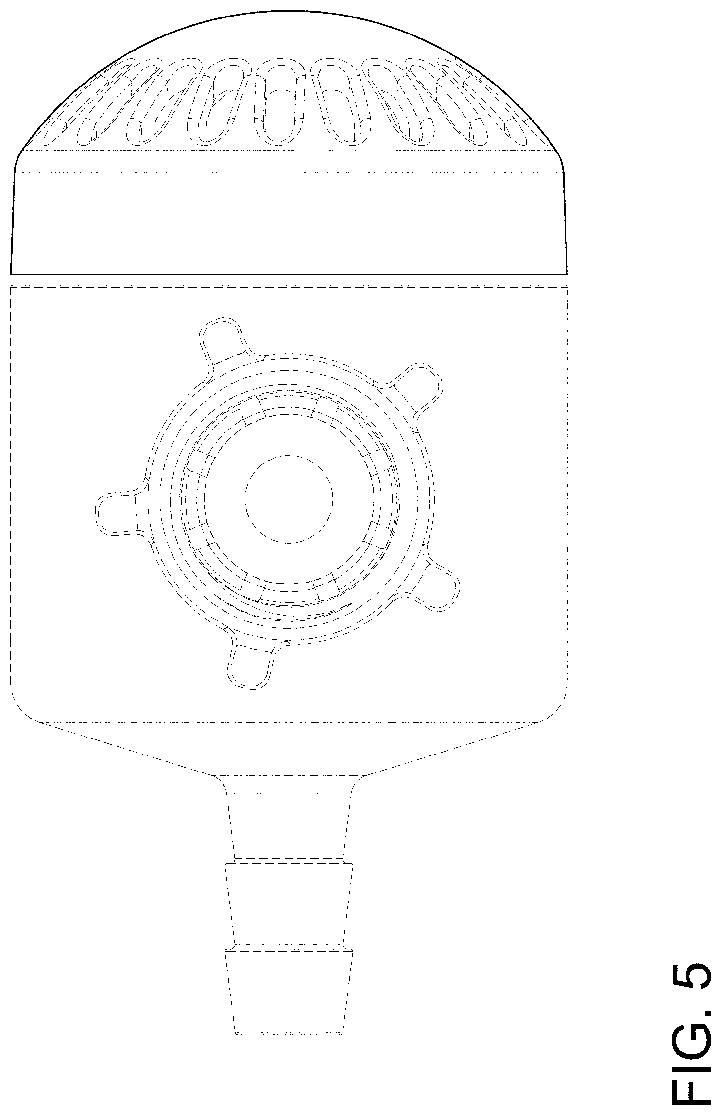
FIG. 5 is a top view thereof;
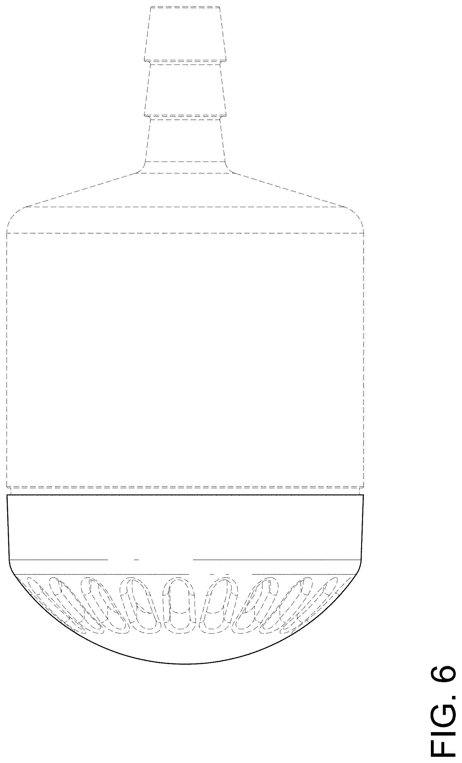
FIG. 6 is a bottom view thereof; and,
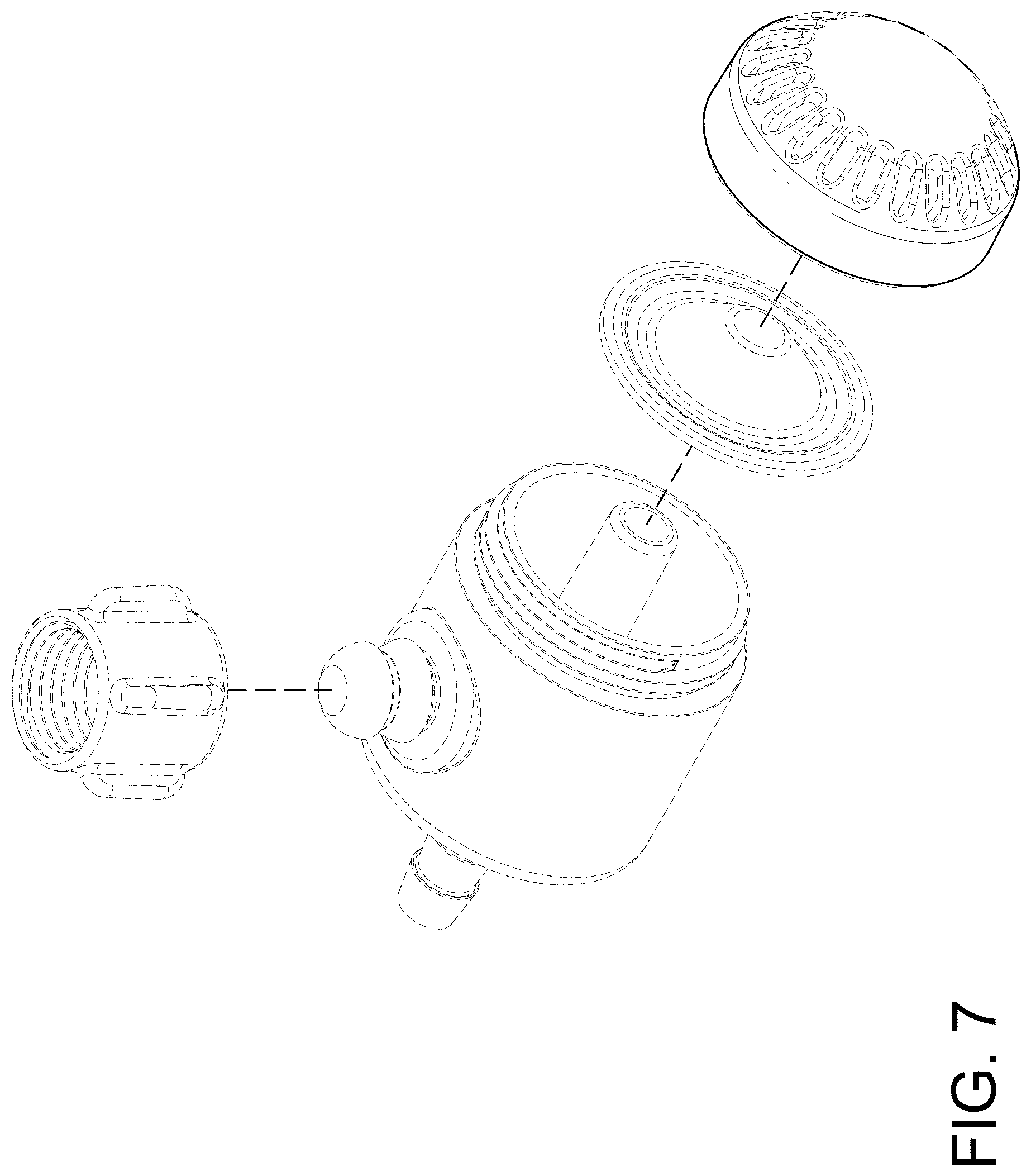
FIG. 7 is another perspective view thereof.
The dashed lines immediately adjacent to the shaded areas in the figures represent the boundaries of the claimed design. The dashed lines in the figures illustrate the portions of the design that form no part of the claimed design. None of the broken lines form any part of the claimed design.
* * * * *
D00000
D00001
D00002
D00003
D00004
D00005
D00006
D00007
XML
uspto.report is an independent third-party trademark research tool that is not affiliated, endorsed, or sponsored by the United States Patent and Trademark Office (USPTO) or any other governmental organization. The information provided by uspto.report is based on publicly available data at the time of writing and is intended for informational purposes only.
While we strive to provide accurate and up-to-date information, we do not guarantee the accuracy, completeness, reliability, or suitability of the information displayed on this site. The use of this site is at your own risk. Any reliance you place on such information is therefore strictly at your own risk.
All official trademark data, including owner information, should be verified by visiting the official USPTO website at www.uspto.gov. This site is not intended to replace professional legal advice and should not be used as a substitute for consulting with a legal professional who is knowledgeable about trademark law.