Electronic cable
Koenig
U.S. patent number D886,065 [Application Number D/635,769] was granted by the patent office on 2020-06-02 for electronic cable. This patent grant is currently assigned to AP Specialties. The grantee listed for this patent is AP Specialties. Invention is credited to Howard Koenig.


| United States Patent | D886,065 |
| Koenig | June 2, 2020 |
Electronic cable
Claims
CLAIM The ornamental design for an electronic cable, as shown and described.
| Inventors: | Koenig; Howard (Dana Point, CA) | ||||||||||
|---|---|---|---|---|---|---|---|---|---|---|---|
| Applicant: |
|
||||||||||
| Assignee: | AP Specialties (San Clemente,
CA) |
||||||||||
| Appl. No.: | D/635,769 | ||||||||||
| Filed: | February 2, 2018 |
Related U.S. Patent Documents
| Application Number | Filing Date | Patent Number | Issue Date | ||
|---|---|---|---|---|---|
| 29514367 | Jan 12, 2015 | D809463 | |||
| Current U.S. Class: | D13/147 |
| Current International Class: | 1303 |
| Field of Search: | ;D13/133,146,147,154,184,199 ;D14/432,433,435.1 |
References Cited [Referenced By]
U.S. Patent Documents
| D594418 | June 2009 | Fujino et al. |
| D684539 | June 2013 | Akana et al. |
| D684976 | June 2013 | Akana et al. |
| 8461465 | June 2013 | Golko et al. |
| 8561879 | October 2013 | Jol et al. |
| D694243 | November 2013 | Akana et al. |
| D699188 | February 2014 | Akana et al. |
| D703145 | April 2014 | Akana et al. |
| D705175 | May 2014 | Chu |
| D705176 | May 2014 | Akana et al. |
| D707680 | June 2014 | Akana et al. |
| D707681 | June 2014 | Akana et al. |
| D713350 | September 2014 | Akana et al. |
| D713351 | September 2014 | Akana et al. |
| D713352 | September 2014 | Akana et al. |
| D713353 | September 2014 | Akana et al. |
| D713354 | September 2014 | Akana et al. |
| D713796 | September 2014 | Akana et al. |
| D716234 | October 2014 | Tien |
| D716235 | October 2014 | Tien |
| D733658 | July 2015 | Yang et al. |
| D745464 | December 2015 | Koenig |
| D751989 | March 2016 | Imai |
| D755724 | May 2016 | Akana et al. |
| D765601 | September 2016 | Palmer |
| D809463 | February 2018 | Koenig |
| D815598 | April 2018 | Koenig |
| D846502 | April 2019 | Akana |
| 2014/0073193 | March 2014 | SooHoo et al. |
| 2014/0136863 | May 2014 | Fritchman et al. |
| 2015/0072557 | March 2015 | Kamei et al. |
| 2015/0340782 | November 2015 | Amini et al. |
| 2015/0364888 | December 2015 | Yu et al. |
| 2017/0264057 | September 2017 | Baum |
| 2011150403 | Dec 2011 | WO | |||
Assistant Examiner: Gingrich; Shawn T
Attorney, Agent or Firm: Lerner, David, Littenberg, Krumholz & Mentlik, LLP
Description
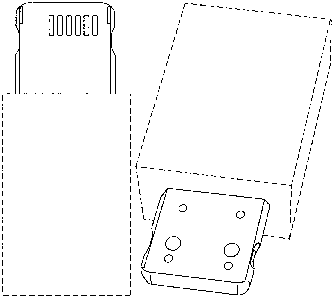
FIG. 1 is a top plan view of Embodiment 1 of an electronic cable showing my new design;
FIG. 2 is a top plan view of Embodiment 2 of an electronic cable showing my new design:
FIG. 3 is a top plan view of Embodiment 3 of an electronic cable showing my new design;
FIG. 4 is a top plan view of Embodiment 4 of an electronic cable showing my new design;
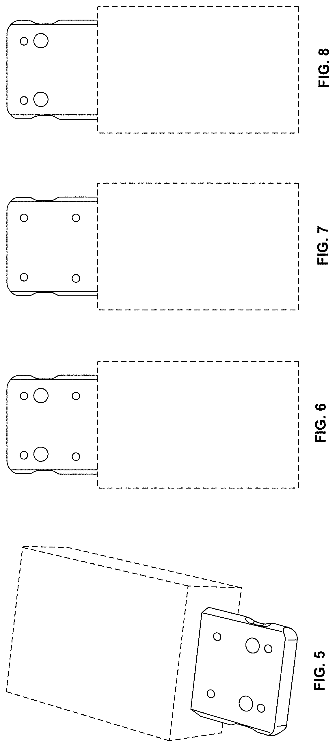
FIG. 5 is a bottom perspective view of Embodiments 1 through 4 thereof;
FIG. 6 is a bottom plan view of Embodiments 1 through 4 thereof;
FIG. 7 is another bottom plan view of FIGS. 1 through 4, which corresponds to Embodiments 5 through 8 of an electronic cable showing my new design;
FIG. 8 is another bottom plan view of FIGS. 1 through 4, which corresponds to Embodiments 9 through 12 of an electronic cable showing my new design;
FIG. 9 is another bottom plan view of FIGS. 1 through 4, which corresponds to Embodiments 13 through 16 of an electronic cable showing my new design;
FIG. 10 is another bottom plan view of FIGS. 1 through 4, which corresponds to Embodiments 17 through 20 of an electronic cable showing my new design;
FIG. 11 is another bottom plan view of FIGS. 1 through 4, which corresponds to Embodiments 21 through 24 of an electronic cable showing my new design;
FIG. 12 is another bottom plan view of FIGS. 1 through 4, which corresponds to Embodiments 25 through 28 of an electronic cable showing my new design;
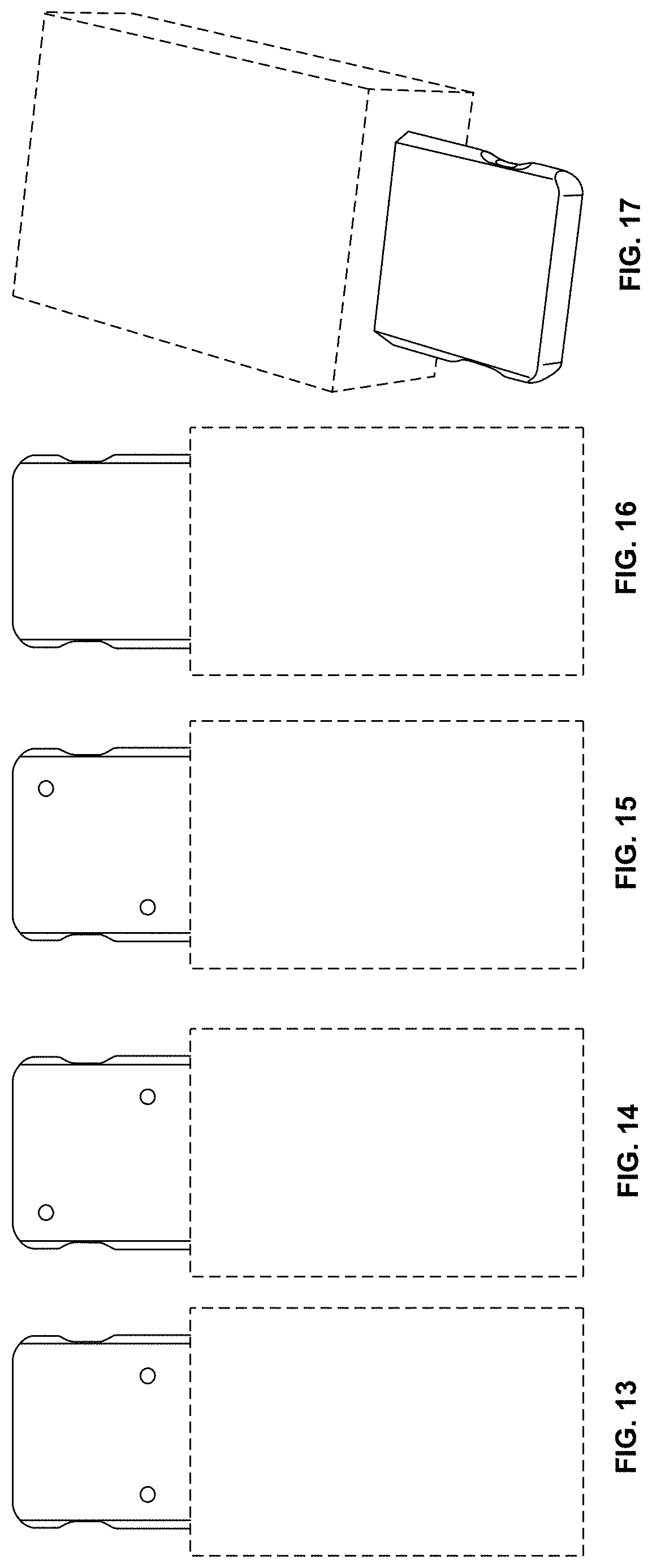
FIG. 13 is another bottom plan view of FIGS. 1 through 4, which corresponds to Embodiments 29 through 32 of an electronic cable showing my new design;
FIG. 14 is another bottom plan view of FIGS. 1 through 4, which corresponds to Embodiments 33 through 36 of an electronic cable showing my new design;
FIG. 15 is another bottom plan view of FIGS. 1 through 4, which corresponds to Embodiments 37 through 40 of an electronic cable showing my new design;
FIG. 16 is another bottom plan view of FIGS. 1 through 4, which corresponds to Embodiments 41 through 44 of an electronic cable showing my new design;
FIG. 17 is bottom perspective view of Embodiments 41 through 44 thereof;
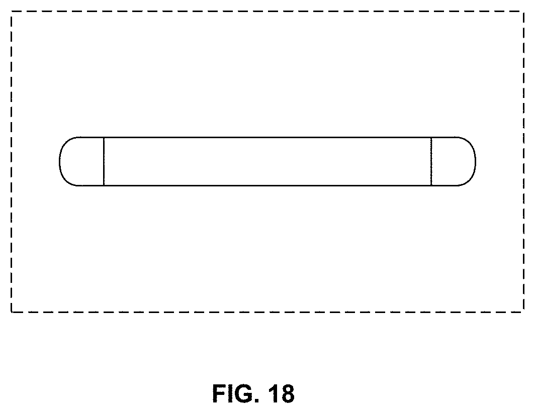
FIG. 18 is a front elevation view of Embodiments 1 through 44 thereof; and,
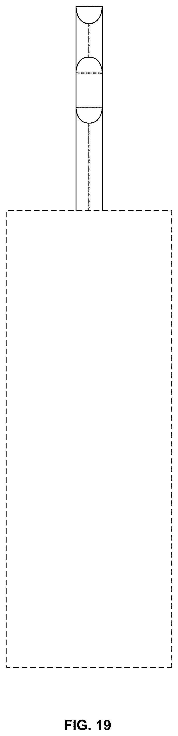
FIG. 19 is a left side elevation view of Embodiments 1 through 44, the right side elevation view being a mirror image thereof.
In the drawing views, the even-broken line represents unclaimed portions of the electronic cable that forms no part of the claimed design.
* * * * *
D00000
D00001
D00002
D00003
D00004
D00005
D00006
XML
uspto.report is an independent third-party trademark research tool that is not affiliated, endorsed, or sponsored by the United States Patent and Trademark Office (USPTO) or any other governmental organization. The information provided by uspto.report is based on publicly available data at the time of writing and is intended for informational purposes only.
While we strive to provide accurate and up-to-date information, we do not guarantee the accuracy, completeness, reliability, or suitability of the information displayed on this site. The use of this site is at your own risk. Any reliance you place on such information is therefore strictly at your own risk.
All official trademark data, including owner information, should be verified by visiting the official USPTO website at www.uspto.gov. This site is not intended to replace professional legal advice and should not be used as a substitute for consulting with a legal professional who is knowledgeable about trademark law.