Communication conference device
Li , et al.
U.S. patent number D885,359 [Application Number D/649,213] was granted by the patent office on 2020-05-26 for communication conference device. This patent grant is currently assigned to COMPAL ELECTRONICS, INC.. The grantee listed for this patent is Li-Fang Chen, Chen-Hsien Cheng, Ching-Hua Li, Yi-Chun Lin. Invention is credited to Li-Fang Chen, Chen-Hsien Cheng, Ching-Hua Li, Yi-Chun Lin.


| United States Patent | D885,359 |
| Li , et al. | May 26, 2020 |
Communication conference device
Claims
CLAIM The ornamental design for a communication conference device, as shown and described.
| Inventors: | Li; Ching-Hua (Taipei, TW), Chen; Li-Fang (Taipei, TW), Cheng; Chen-Hsien (Taipei, TW), Lin; Yi-Chun (Taipei, TW) | ||||||||||
|---|---|---|---|---|---|---|---|---|---|---|---|
| Applicant: |
|
||||||||||
| Assignee: | COMPAL ELECTRONICS, INC.
(Taipei, TW) |
||||||||||
| Appl. No.: | D/649,213 | ||||||||||
| Filed: | May 29, 2018 |
| Current U.S. Class: | D14/148 |
| Current International Class: | 1403 |
| Field of Search: | ;D14/140,140.1,140.7,140.8,141.2,142,144,147,148,149,150,151,158,159,188,243,247,248,299,329,130,338,138R,138AA ;D21/517 |
References Cited [Referenced By]
U.S. Patent Documents
| D284655 | July 1986 | Marshall |
| D285198 | August 1986 | Danielson |
| D285790 | September 1986 | Harrison |
| D287124 | December 1986 | Becker |
| D287362 | December 1986 | Rittenhouse |
| D287964 | January 1987 | Perkins |
| D289755 | May 1987 | Todeschini |
| D301874 | June 1989 | Roegner |
| D346171 | April 1994 | Ratcliffe |
| D346383 | April 1994 | Mehle-Hohnjec |
| D346799 | May 1994 | Hosoe |
| D346800 | May 1994 | Hosoe |
| D347007 | May 1994 | Hosoe |
| D352282 | November 1994 | Toh |
| D353373 | December 1994 | Delhaes |
| D363290 | October 1995 | Kim |
| D369796 | May 1996 | Grewe |
| D372919 | August 1996 | Nagele |
| D388086 | December 1997 | Constantine |
| D403678 | January 1999 | Hawley |
| D424558 | May 2000 | Hong |
| D463388 | September 2002 | Thomsen |
| D555132 | November 2007 | Kim |
| 7433654 | October 2008 | Reed |
| D587236 | February 2009 | Haberl |
| D612846 | March 2010 | Matsuoka |
| D640687 | June 2011 | Matsuoka |
| 8060161 | November 2011 | Kwak |
| D655705 | March 2012 | Matsuoka |
| D662933 | July 2012 | Matsuoka |
| D682246 | May 2013 | Boqueho |
| D697626 | January 2014 | Laplante |
| D705751 | May 2014 | Wenger et al. |
| D724085 | March 2015 | Dowd |
| D734289 | July 2015 | Jeon |
| D754091 | April 2016 | Ookawa |
| D757676 | May 2016 | Hoehn |
| D776076 | January 2017 | Jeon |
| D783009 | April 2017 | Moore |
| D783568 | April 2017 | Pista |
| D792867 | July 2017 | Maxwell |
| D793987 | August 2017 | Hoehn |
| D812031 | March 2018 | Hoehn |
| D830326 | October 2018 | Lin |
| 2004/0266477 | December 2004 | Murata |
| 2008/0242380 | October 2008 | Kajihara |
| 2009/0088222 | April 2009 | Numano |
| 2017/0126871 | May 2017 | Babayev |
| 2019/0215393 | July 2019 | Li |
Attorney, Agent or Firm: JCIPRNET
Description
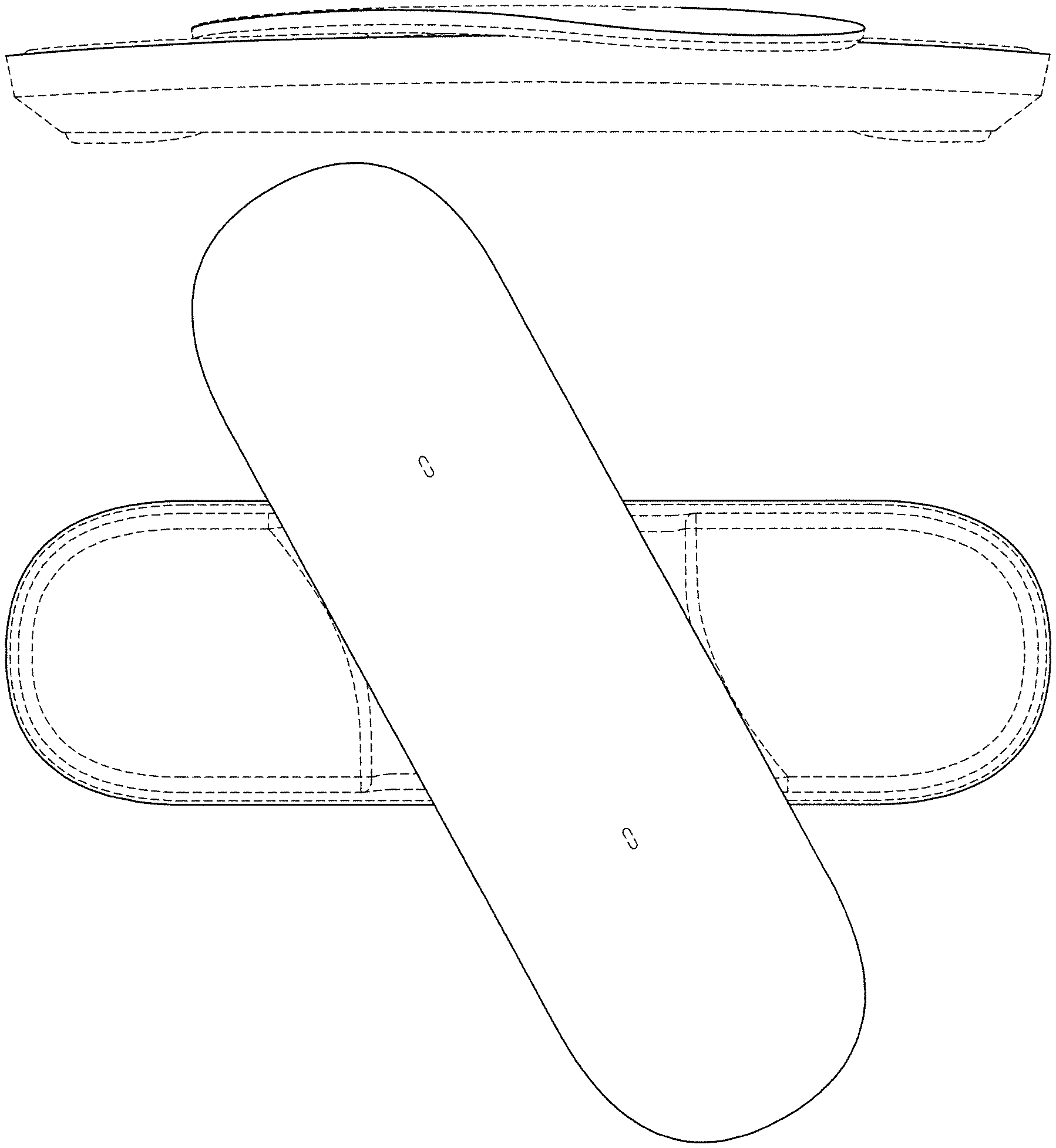
FIG. 1 is a front view of a communication conference device showing our new design in a position for use with the upper member inclined to the base;
FIG. 2 is a rear view thereof;
FIG. 3 is a left side view thereof;
FIG. 4 is a right side view thereof;
FIG. 5 is a top view thereof;
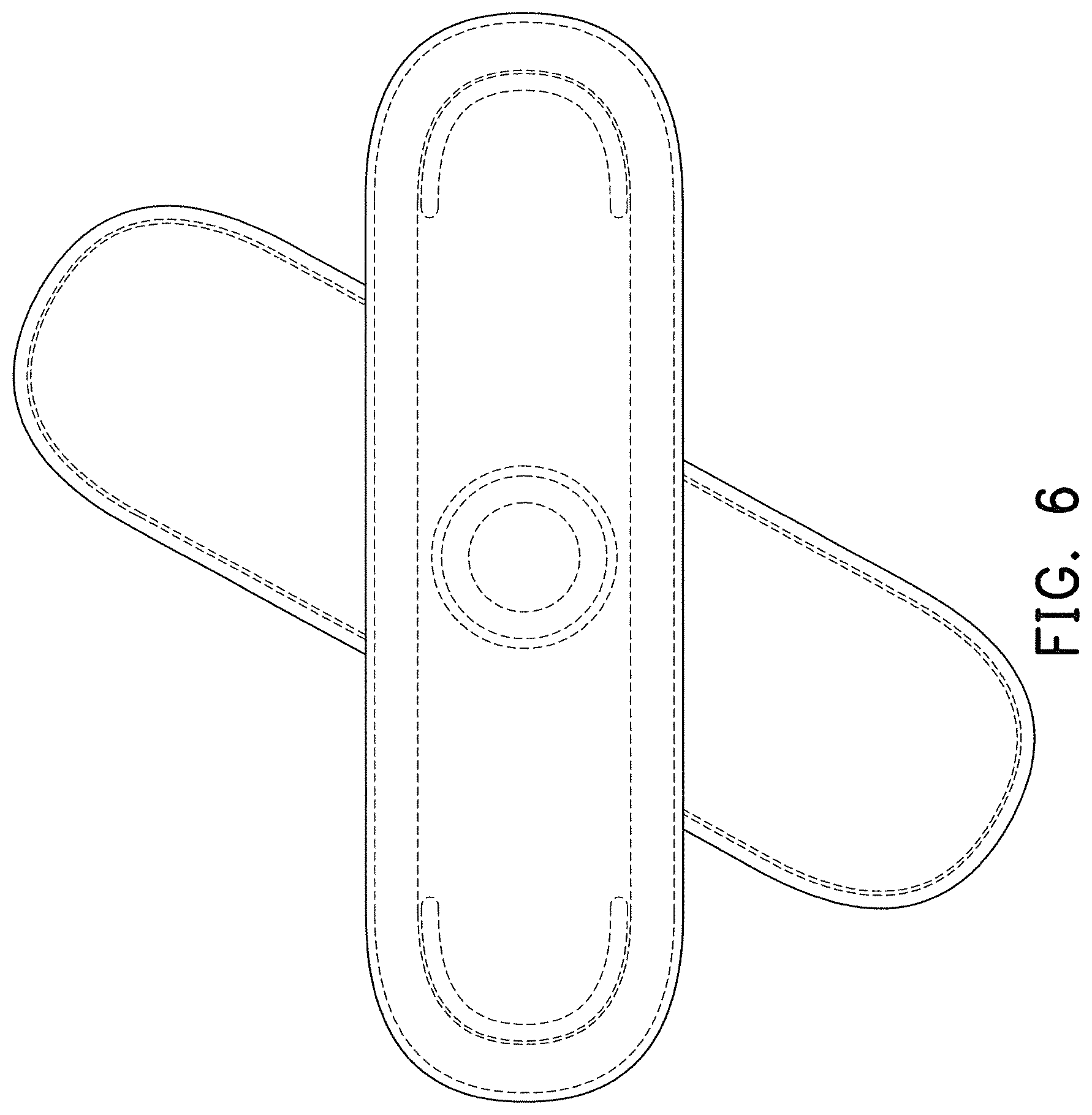
FIG. 6 is a bottom view thereof;
FIG. 7 is another top view thereof, showing an alternate rotated position for use wherein the upper member is parallel to the base;
FIG. 8 is a perspective view thereof;
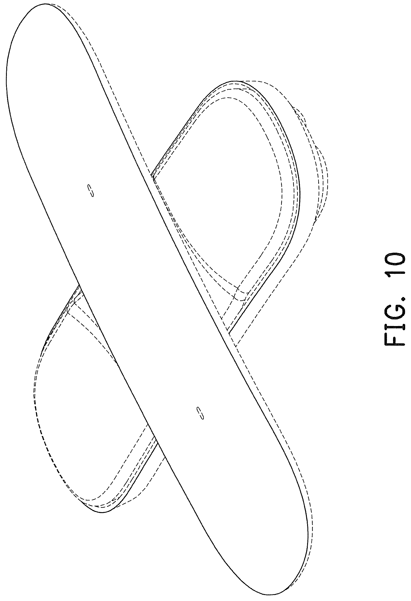
FIG. 9 is another top view thereof, showing another alternate rotated position for use wherein the upper member is perpendicular to the base; and,
FIG. 10 is a perspective view thereof.
The broken lines depict portions of the communication conference device that form no part of the claimed design.
All surfaces shown between the broken and solid lines and the broken lines themselves form no part of the claimed design.
* * * * *
D00000
D00001
D00002
D00003
D00004
D00005
D00006
D00007
D00008
D00009
D00010
XML
uspto.report is an independent third-party trademark research tool that is not affiliated, endorsed, or sponsored by the United States Patent and Trademark Office (USPTO) or any other governmental organization. The information provided by uspto.report is based on publicly available data at the time of writing and is intended for informational purposes only.
While we strive to provide accurate and up-to-date information, we do not guarantee the accuracy, completeness, reliability, or suitability of the information displayed on this site. The use of this site is at your own risk. Any reliance you place on such information is therefore strictly at your own risk.
All official trademark data, including owner information, should be verified by visiting the official USPTO website at www.uspto.gov. This site is not intended to replace professional legal advice and should not be used as a substitute for consulting with a legal professional who is knowledgeable about trademark law.