Combined grip and support for handheld device
Park
U.S. patent number D883,272 [Application Number D/678,460] was granted by the patent office on 2020-05-05 for combined grip and support for handheld device. This patent grant is currently assigned to ES Distribution, LLC. The grantee listed for this patent is ES Distribution, LLC. Invention is credited to Joon Park.


| United States Patent | D883,272 |
| Park | May 5, 2020 |
Combined grip and support for handheld device
Claims
CLAIM The ornamental design for a combined grip and support for handheld device, substantially as shown.
| Inventors: | Park; Joon (Redondo Beach, CA) | ||||||||||
|---|---|---|---|---|---|---|---|---|---|---|---|
| Applicant: |
|
||||||||||
| Assignee: | ES Distribution, LLC (Sudbury,
MA) |
||||||||||
| Appl. No.: | D/678,460 | ||||||||||
| Filed: | January 29, 2019 |
| Current U.S. Class: | D14/253 |
| Current International Class: | 1403 |
| Field of Search: | ;D14/251-253,447,452 ;D12/415 ;D3/218 ;D8/349,363 ;D6/656.11,656.12,656.13,656.15,656.16,655,655.1,675.1 |
References Cited [Referenced By]
U.S. Patent Documents
| D656479 | March 2012 | Lin |
| D658168 | April 2012 | Werth |
| 8220767 | July 2012 | Lin |
| D679700 | April 2013 | Werth |
| 8424831 | April 2013 | Lin |
| D712394 | September 2014 | Booth |
| D723536 | March 2015 | Werth |
| D735695 | August 2015 | Murphy |
| 9259077 | February 2016 | Murphy et al. |
| D778899 | February 2017 | Khalili |
| D786235 | May 2017 | Huotari |
| D826917 | August 2018 | Zhong |
| D842851 | March 2019 | Leitman |
| D864188 | October 2019 | Che |
Other References
|
Datasheet--KickGrip--Universal Car Vent Mount, Phone Stand, Belt Clip, retrieved from the internet < https://www.amazon.com/KickGrip-Universal-Mount-Phone-Stand/dp/B01NCZB87U- >. cited by applicant. |
Primary Examiner: Hallmark; Janice
Attorney, Agent or Firm: Cesari and McKenna, LLP
Description
FIG. 1 is an isometric view from the front of a combined grip and support for handheld device, with a support in a closed position, incorporating the design;
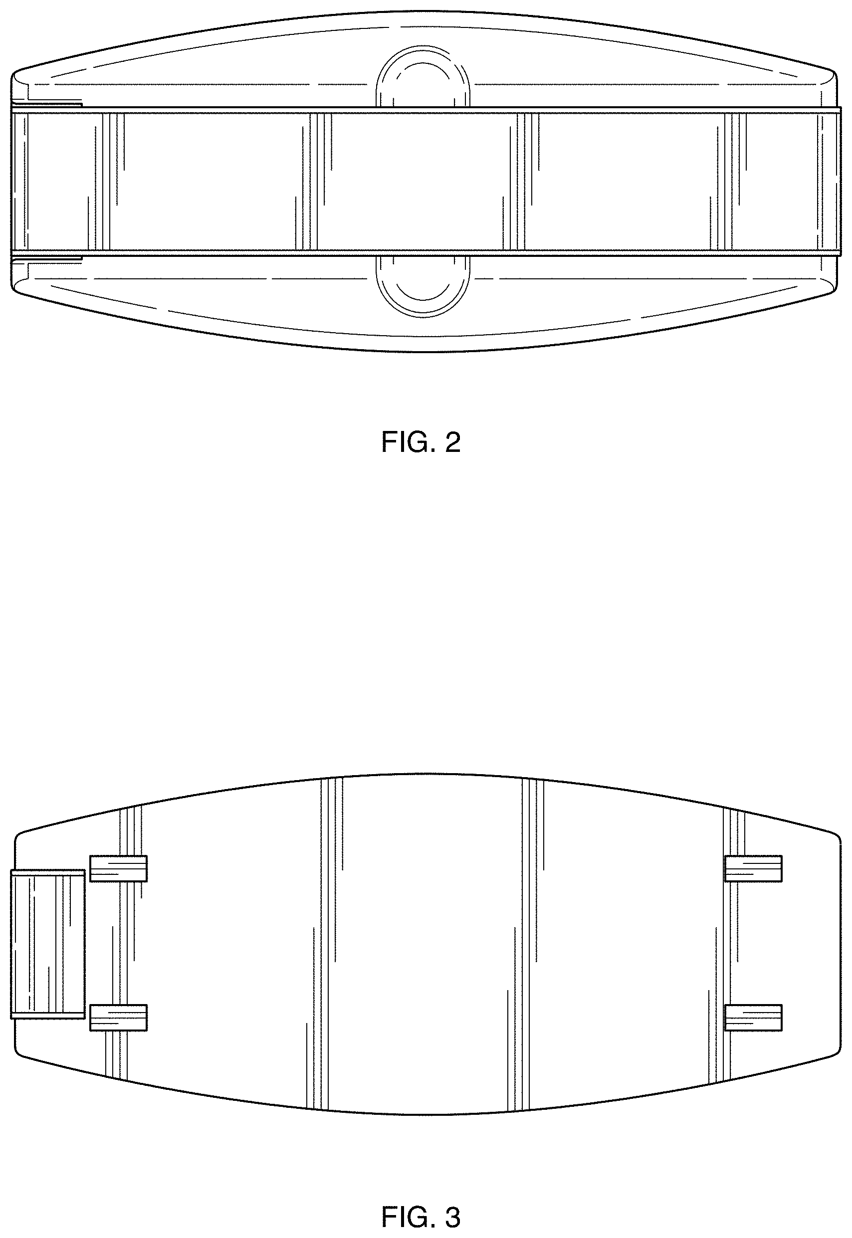
FIG. 2 is a front elevation view thereof;
FIG. 3 is a back elevation view thereof;
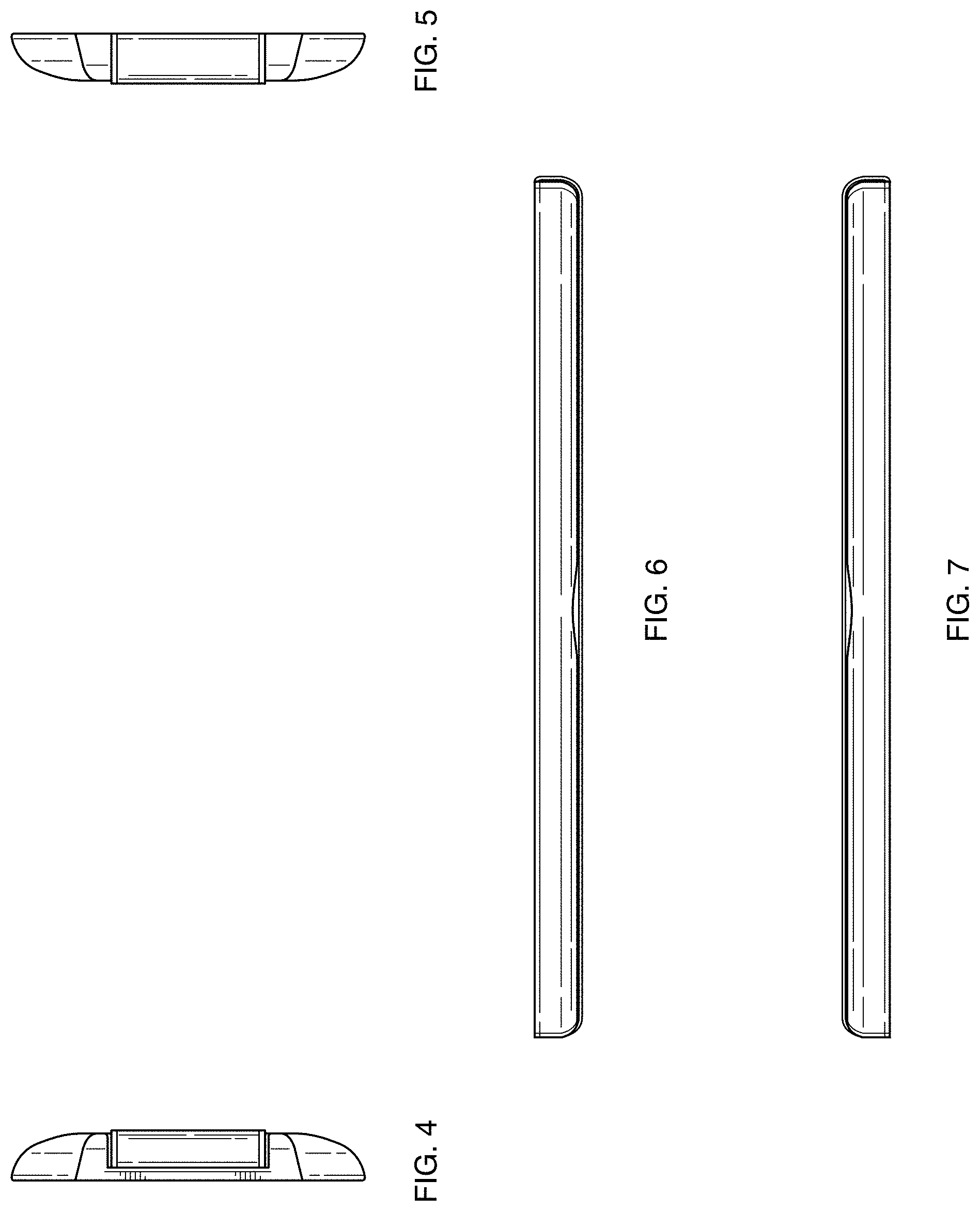
FIG. 4 is a left-side elevation view thereof;
FIG. 5 is a right-side elevation view thereof;
FIG. 6 is a top view thereof;
FIG. 7 is a bottom view thereof;
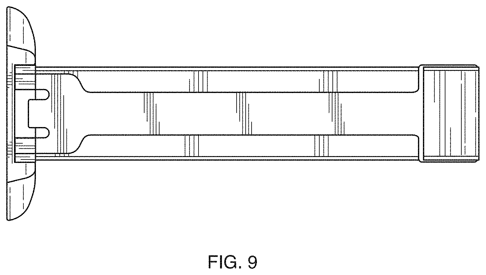
FIG. 8 is an isometric view from the front, with the support in an open position, thereof; and,
FIG. 9 is a left-side elevation view, with the support in an open position, thereof.
* * * * *
References
D00000
D00001
D00002
D00003
D00004
D00005
XML
uspto.report is an independent third-party trademark research tool that is not affiliated, endorsed, or sponsored by the United States Patent and Trademark Office (USPTO) or any other governmental organization. The information provided by uspto.report is based on publicly available data at the time of writing and is intended for informational purposes only.
While we strive to provide accurate and up-to-date information, we do not guarantee the accuracy, completeness, reliability, or suitability of the information displayed on this site. The use of this site is at your own risk. Any reliance you place on such information is therefore strictly at your own risk.
All official trademark data, including owner information, should be verified by visiting the official USPTO website at www.uspto.gov. This site is not intended to replace professional legal advice and should not be used as a substitute for consulting with a legal professional who is knowledgeable about trademark law.