Dual port antenna assembly
Keyrouz , et al.
U.S. patent number D883,962 [Application Number D/623,485] was granted by the patent office on 2020-05-12 for dual port antenna assembly. This patent grant is currently assigned to The Antenna Company International N.V.. The grantee listed for this patent is The Antenna Company International N.V.. Invention is credited to Thomas Bolz, Diego Caratelli, Carlos Moreno De Jong Van Coevorden, Shady Keyrouz, Jarmos Pirneskoski.


View All Diagrams
| United States Patent | D883,962 |
| Keyrouz , et al. | May 12, 2020 |
Dual port antenna assembly
Claims
CLAIM The ornamental design for a dual port antenna assembly, as shown and described.
| Inventors: | Keyrouz; Shady (Eindhoven, NL), Caratelli; Diego (Duizel, NL), De Jong Van Coevorden; Carlos Moreno (Eindhoven, NL), Pirneskoski; Jarmos (Eindhoven, NL), Bolz; Thomas (Sonsbeck, DE) | ||||||||||
|---|---|---|---|---|---|---|---|---|---|---|---|
| Applicant: |
|
||||||||||
| Assignee: | The Antenna Company International
N.V. (Willemstad, CW) |
||||||||||
| Appl. No.: | D/623,485 | ||||||||||
| Filed: | October 25, 2017 |
Related U.S. Patent Documents
| Application Number | Filing Date | Patent Number | Issue Date | ||
|---|---|---|---|---|---|
| 29612467 | Aug 1, 2017 | D856313 | |||
Foreign Application Priority Data
| Apr 25, 2017 [NL] | 2018779 | |||
| Jul 28, 2017 [NL] | 2019365 | |||
| Current U.S. Class: | D14/230 |
| Current International Class: | 1403 |
| Field of Search: | ;D14/230-238,138,172,188,203.1,203.3,203.6,204,216,221,238.1,240,242,299,314,343,356,358,496,509 ;D13/182 |
References Cited [Referenced By]
U.S. Patent Documents
| 6034649 | March 2000 | Wilson |
| D459706 | July 2002 | Ebihara |
| 6597324 | July 2003 | Eriksson |
| D505925 | June 2005 | Koo |
| D710832 | August 2014 | Yang |
| D713392 | September 2014 | Podduturi |
| D733104 | June 2015 | Yang |
| D740239 | October 2015 | Amini |
| D754108 | April 2016 | Yang |
| 9502781 | November 2016 | Battarov |
| D798846 | October 2017 | Chang |
| D802569 | November 2017 | Zheng |
| D815071 | April 2018 | Yang |
| D838694 | January 2019 | Chang |
| 10224643 | March 2019 | Moon |
| 10320092 | June 2019 | Le |
| D856313 | August 2019 | Keyrouz |
| 2001/0007445 | July 2001 | Pankinaho |
| 2004/0056804 | March 2004 | Kadambi et al. |
| 2004/0080457 | April 2004 | Guo et al. |
| 2004/0085244 | May 2004 | Kadambi et al. |
| 2004/0125030 | July 2004 | Sung et al. |
| 2004/0263396 | December 2004 | Sung |
| 2006/0290572 | December 2006 | Chan |
| 2009/0051595 | February 2009 | Wang et al. |
| 2014/0118191 | May 2014 | Smith |
| 2015/0214630 | July 2015 | Shimura |
| 2016/0344093 | November 2016 | Tagi et al. |
| 106299727 | Jan 2017 | CN | |||
| 2017061869 | Apr 2017 | WO | |||
Other References
|
Zarghooni, et al. "Supershaped Metamaterial Unit-cells Using the Gielis Formula", 2015, IEEE International Symposium on Antennas and Propagation & USNC/URSI National Radio Science Meeting, Jul. 19, 2015, pp. 458-459. cited by applicant. |
Primary Examiner: Asch; Jeffrey D
Assistant Examiner: Caruso; Rebekah A
Attorney, Agent or Firm: The Webb Law Firm
Description
FIG. 1 is a top perspective view of a dual port antenna assembly, showing our new design;
FIG. 2 is a top view thereof;
FIG. 3 is a front view thereof;
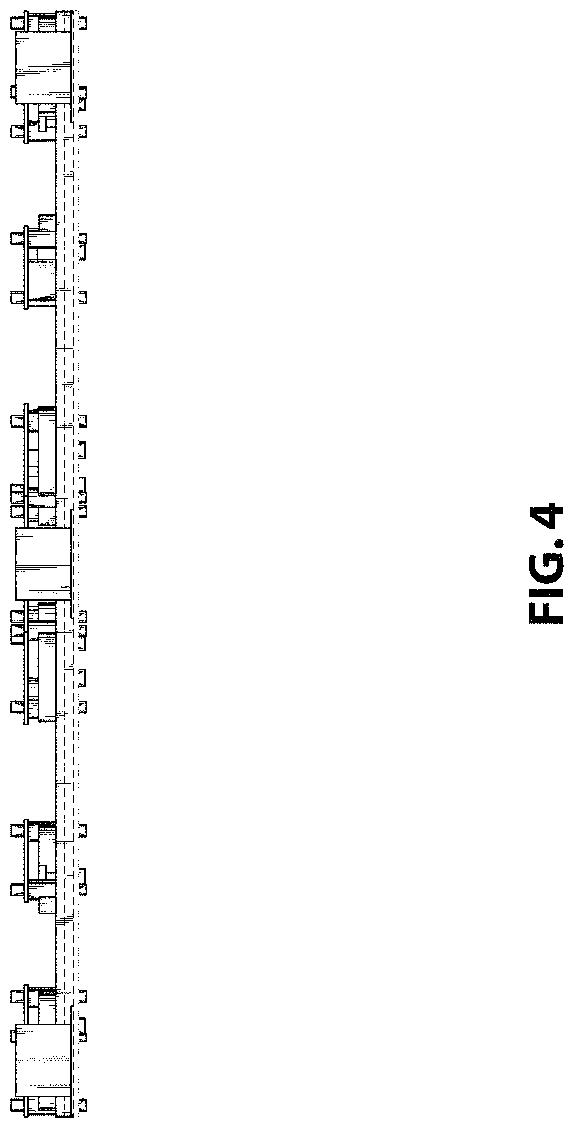
FIG. 4 is a side view thereof;
FIG. 5 is a bottom view thereof;
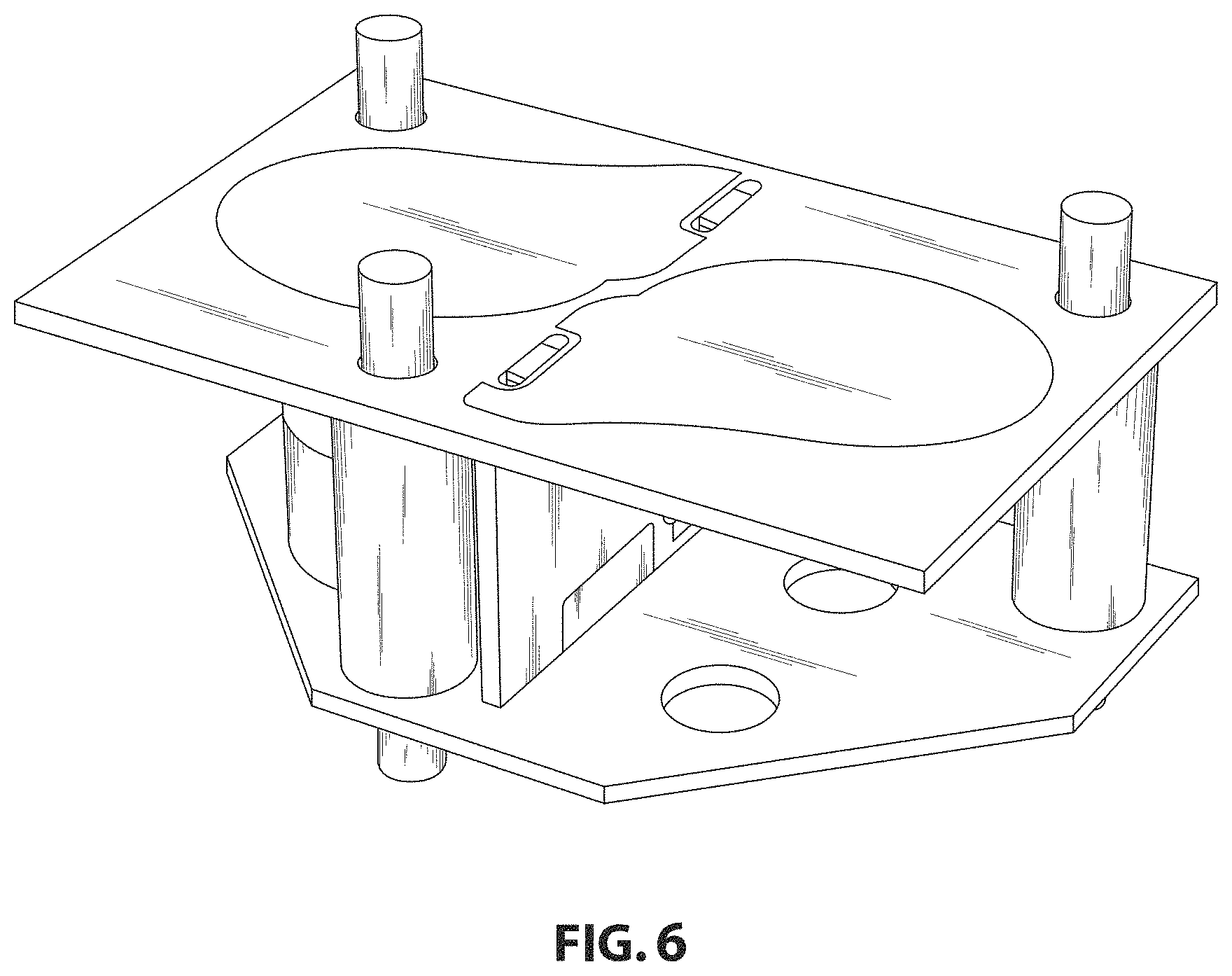
FIG. 6 is a top perspective view of one of the dual port antenna of FIG. 1;
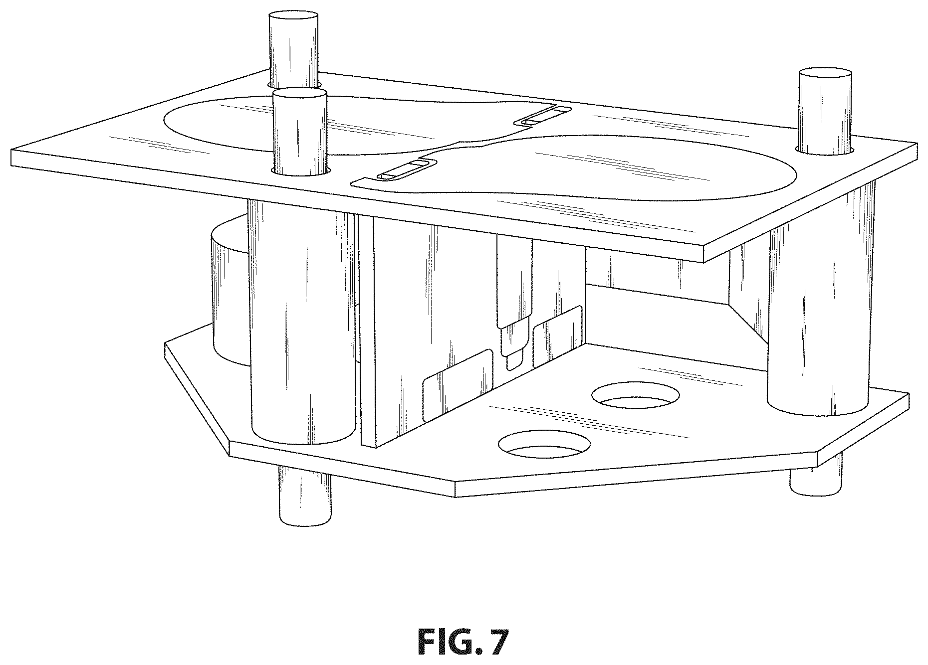
FIG. 7 is a front perspective view of the dual port antenna of FIG. 6;
FIG. 8 is another top perspective view of the dual port antenna of FIG. 6;
FIG. 9 is another front perspective view of the dual port antenna of FIG. 6;
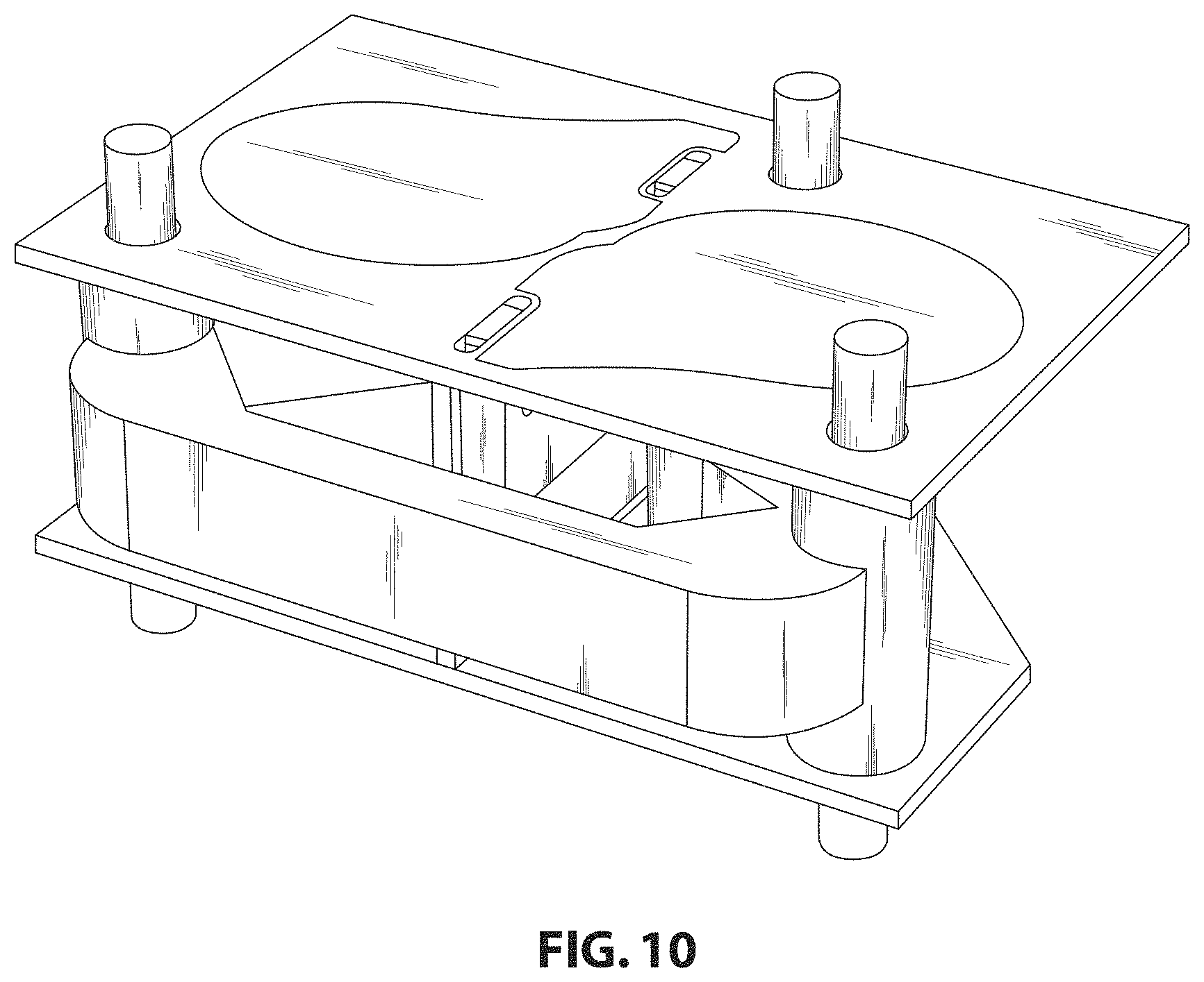
FIG. 10 is a top rear perspective view of the dual port antenna of FIG. 6;
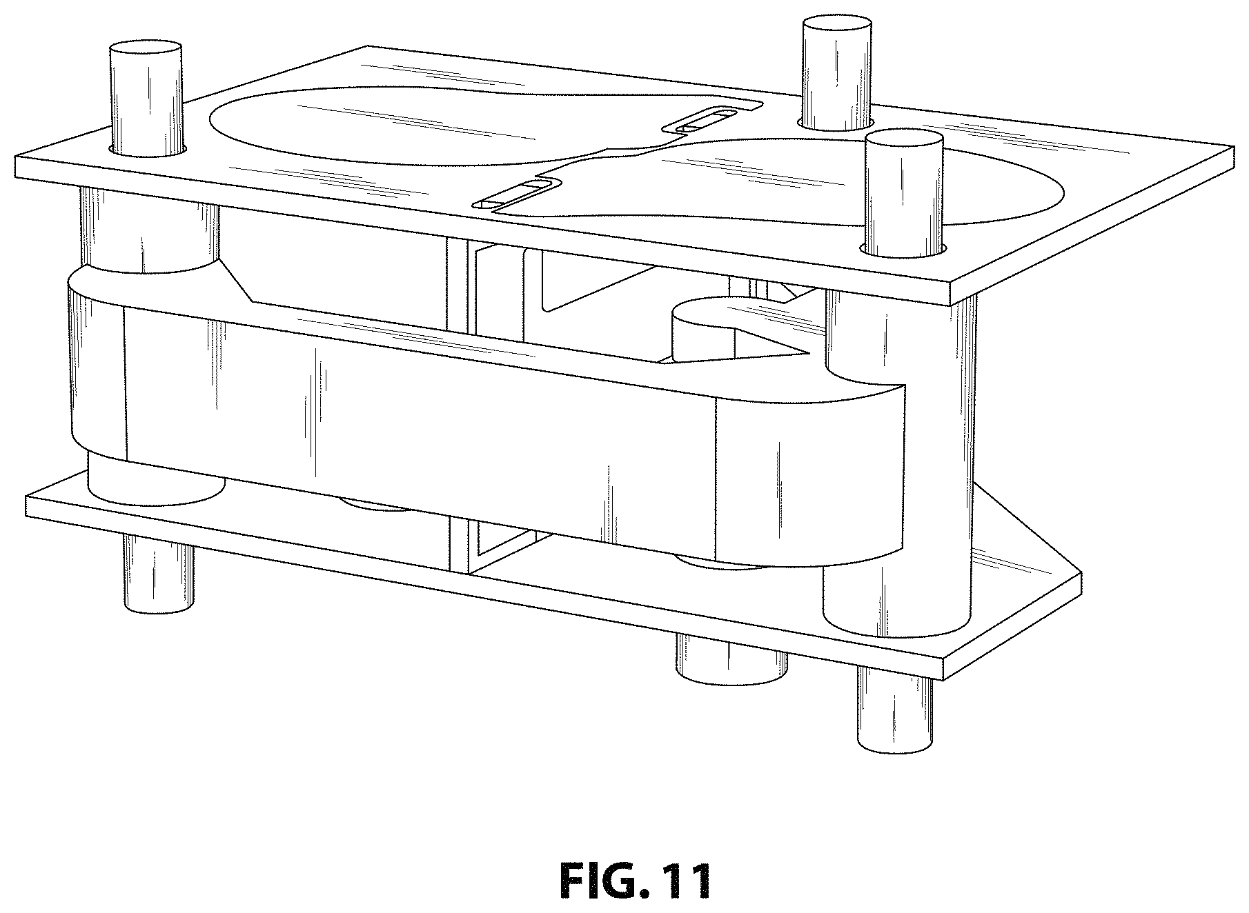
FIG. 11 is a rear perspective view of the dual port antenna of FIG. 6;
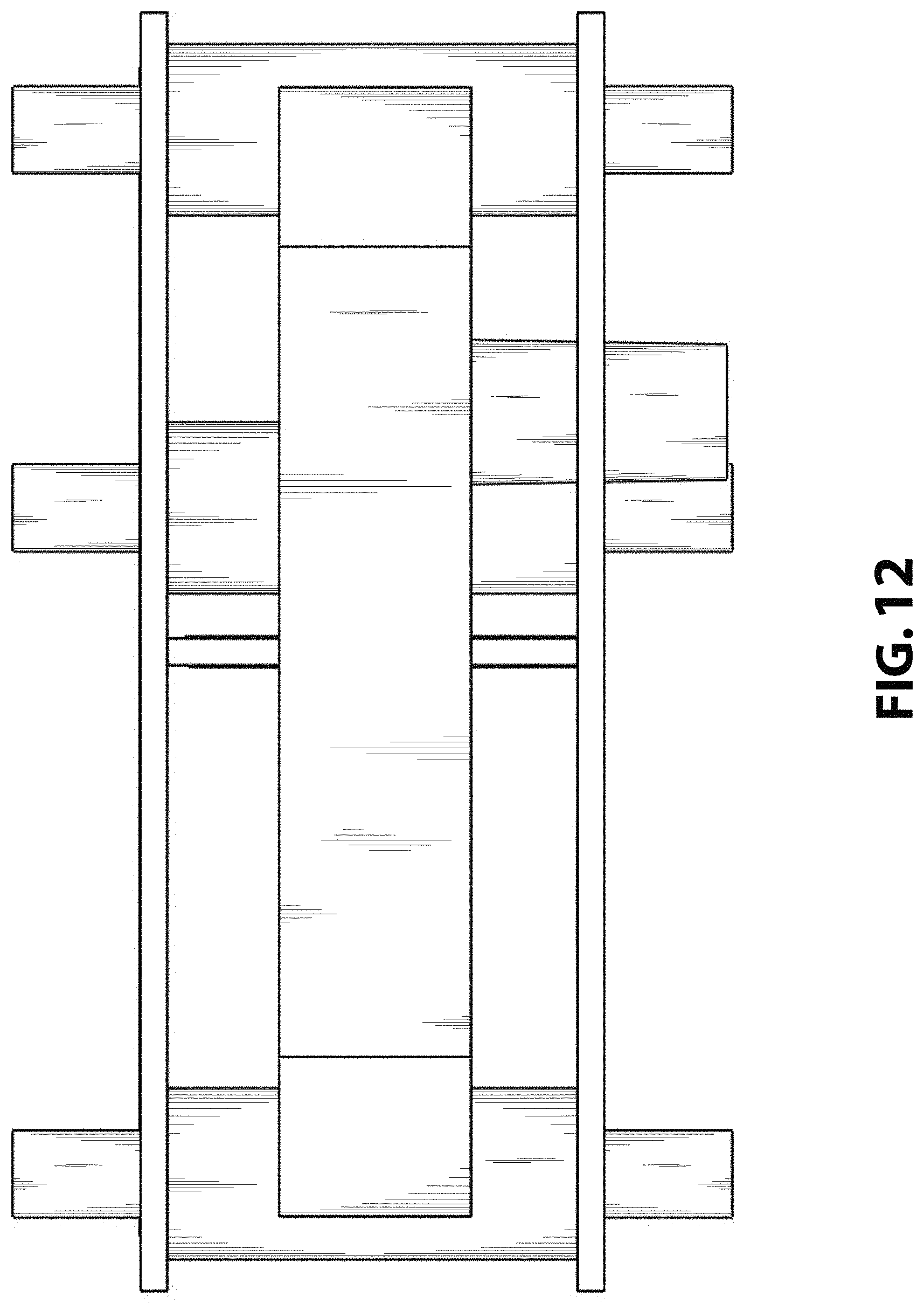
FIG. 12 is a rear view of the dual port antenna of FIG. 6;
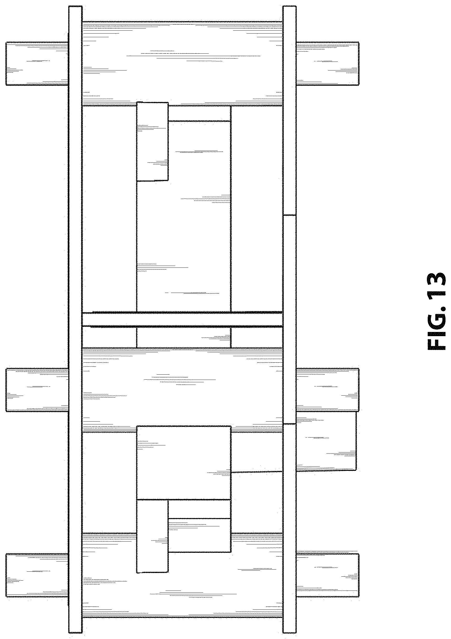
FIG. 13 is a front view of the dual port antenna of FIG. 6;
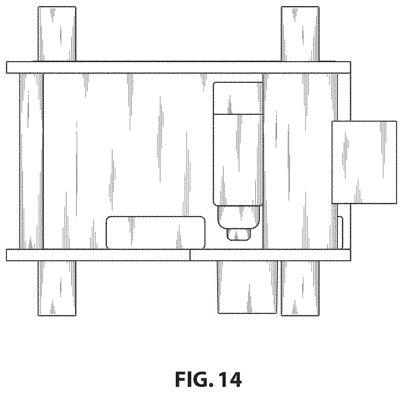
FIG. 14 is a right side view of the dual port antenna of FIG. 6;
FIG. 15 is a left side view of the dual port antenna of FIG. 6; and,
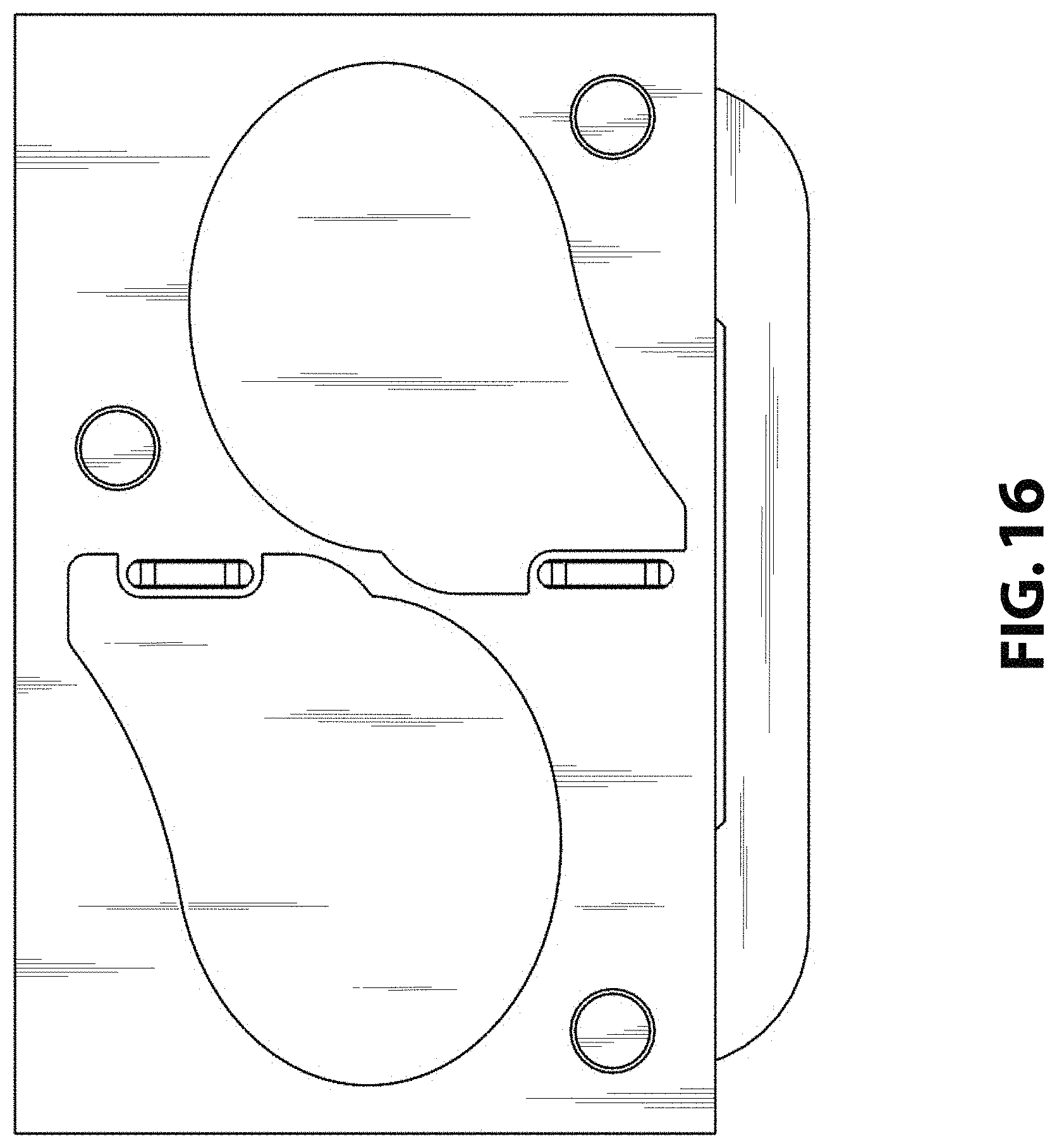
FIG. 16 is a top view of the dual port antenna of FIG. 6.
Each of the dual port antennas provided on the top surface of the article are identical in appearance to the dual port antenna depicted in FIGS. 6-16.
The broken lines shown in FIGS. 1-5 depict components of the dual port antenna assembly that form no part of the claimed design and are included for environmental purposes only.
* * * * *
D00000
D00001
D00002
D00003
D00004
D00005
D00006
D00007
D00008
D00009
D00010
D00011
D00012
D00013
D00014
D00015

D00016
XML
uspto.report is an independent third-party trademark research tool that is not affiliated, endorsed, or sponsored by the United States Patent and Trademark Office (USPTO) or any other governmental organization. The information provided by uspto.report is based on publicly available data at the time of writing and is intended for informational purposes only.
While we strive to provide accurate and up-to-date information, we do not guarantee the accuracy, completeness, reliability, or suitability of the information displayed on this site. The use of this site is at your own risk. Any reliance you place on such information is therefore strictly at your own risk.
All official trademark data, including owner information, should be verified by visiting the official USPTO website at www.uspto.gov. This site is not intended to replace professional legal advice and should not be used as a substitute for consulting with a legal professional who is knowledgeable about trademark law.