Electrical extension cord receptacle end
Eshelman , et al.
U.S. patent number D879,721 [Application Number D/692,904] was granted by the patent office on 2020-03-31 for electrical extension cord receptacle end. This patent grant is currently assigned to 360 Electrical, L.L.C.. The grantee listed for this patent is 360 Electrical, LLC. Invention is credited to Cameron Bigler, Adam Boushley, Brandon Eshelman.
| United States Patent | D879,721 |
| Eshelman , et al. | March 31, 2020 |
Electrical extension cord receptacle end
Claims
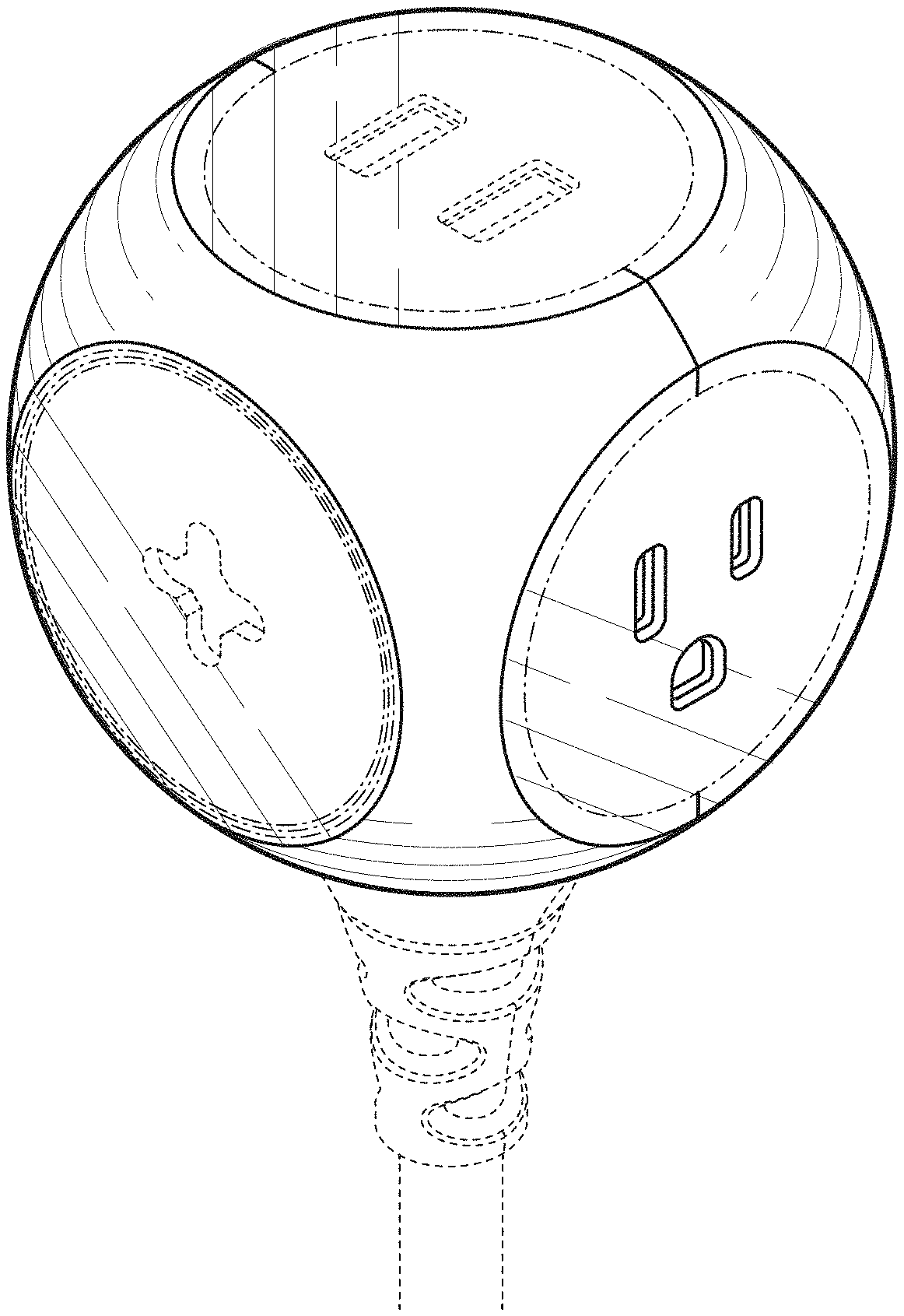
CLAIM The ornamental design for an electrical extension cord receptacle end, substantially as shown and described.
| Inventors: | Eshelman; Brandon (Salt Lake City, UT), Bigler; Cameron (Lehi, UT), Boushley; Adam (Midvale, UT) | ||||||||||
|---|---|---|---|---|---|---|---|---|---|---|---|
| Applicant: |
|
||||||||||
| Assignee: | 360 Electrical, L.L.C. (Salt
Lake City, UT) |
||||||||||
| Appl. No.: | D/692,904 | ||||||||||
| Filed: | May 29, 2019 |
Related U.S. Patent Documents
| Application Number | Filing Date | Patent Number | Issue Date | ||
|---|---|---|---|---|---|
| 29670953 | Nov 21, 2018 | ||||
| 29582848 | Nov 27, 2018 | D834520 | |||
| Current U.S. Class: | D13/139.7 |
| Current International Class: | 1303 |
| Field of Search: | ;D13/139.1-139.8,108,137.1-137.4,146 ;D14/433 |
References Cited [Referenced By]
U.S. Patent Documents
| D155472 | October 1949 | BecVar et al. |
| D325723 | April 1992 | Gary et al. |
| D405416 | February 1999 | Byrne |
| D435516 | December 2000 | Stekelenburg |
| D448730 | October 2001 | Lee |
| 6315617 | November 2001 | Al-Sabah |
| D459307 | June 2002 | Nieto |
| D469064 | January 2003 | Nieto |
| D469403 | January 2003 | Nieto |
| D472520 | April 2003 | Genicevitch |
| D481009 | October 2003 | Stekelenburg |
| D482326 | November 2003 | Stekelenburg |
| D540257 | April 2007 | Ivanova et al. |
| D556689 | December 2007 | Lee et al. |
| D559783 | January 2008 | Matzdorff et al. |
| D566654 | April 2008 | Ivanova et al. |
| D603049 | October 2009 | Hardy et al. |
| 7862385 | January 2011 | Lee |
| D639742 | June 2011 | Doucet |
| D640199 | June 2011 | Wilson |
| D651977 | January 2012 | Lee |
| D653215 | January 2012 | Lam |
| D681548 | May 2013 | Zhang et al. |
| D685328 | July 2013 | Kirtland |
| D696354 | December 2013 | Barry |
| D718714 | December 2014 | Si |
| D718715 | December 2014 | Si |
| D736709 | August 2015 | Byrne et al. |
| D736710 | August 2015 | Lin |
| D739355 | September 2015 | D'Aubeterre |
| D739821 | September 2015 | Byrne |
| D741265 | October 2015 | Lee |
| D771750 | November 2016 | Fjelstad |
| D775589 | January 2017 | Soffer |
| D790459 | June 2017 | Eshelman |
| D794029 | August 2017 | Lin |
| D796442 | September 2017 | Xu |
| D801438 | October 2017 | Fjelstad |
| D801439 | October 2017 | Fjelstad |
| D806175 | December 2017 | Fjelstad |
| D817887 | May 2018 | Yu |
| D819571 | June 2018 | Eshelman |
| D821328 | June 2018 | Byrne et al. |
| D826162 | August 2018 | Byrne |
| D826163 | August 2018 | Xu |
| D829663 | October 2018 | Liu |
| D830307 | October 2018 | Liu |
| D834520 | November 2018 | Eshelman |
| D844566 | April 2019 | Yu |
| D845902 | April 2019 | Xu |
| D846498 | April 2019 | Byrne |
| D846500 | April 2019 | Xu |
| D851598 | June 2019 | Liang |
| 2009/0156061 | June 2009 | Bernstein |
| 302053975 | Aug 2012 | CN | |||
| 302153851 | Oct 2012 | CN | |||
| 303287272 | Jul 2015 | CN | |||
| 303423238 | Oct 2015 | CN | |||
| 303428639 | Nov 2015 | CN | |||
| 303647455 | Apr 2016 | CN | |||
| 3034138612 | May 2017 | CN | |||
Other References
|
Non Final Office Action dated Mar. 15, 2019 for U.S. Appl. No. 29/670,953 "Electrical Extension Cord Receptacle End" Eshelman, 8 pages. cited by applicant. |
Primary Examiner: Shields; Rhea
Attorney, Agent or Firm: Lee & Hayes, P.C.
Description
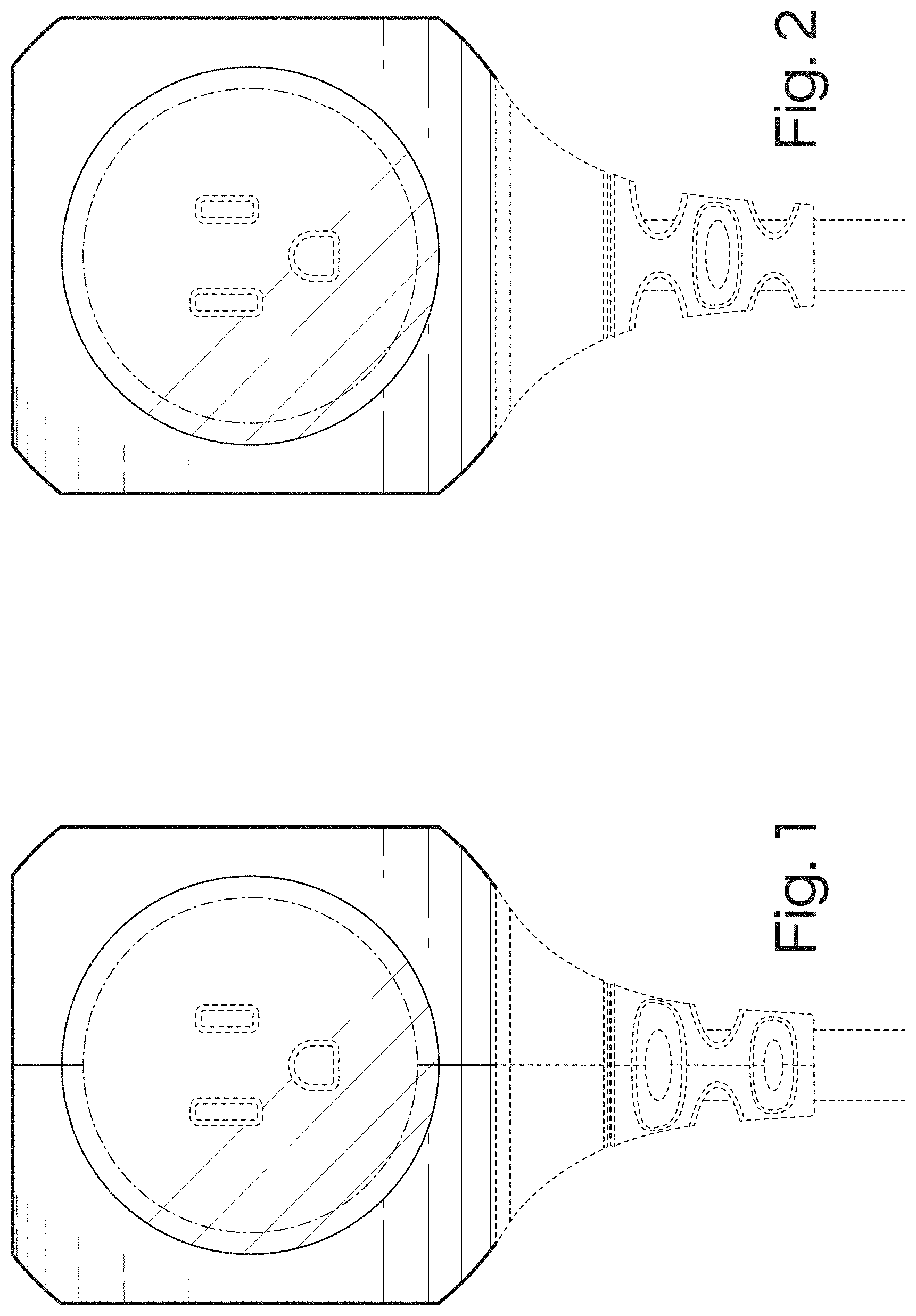
FIG. 1 is a right side elevation view of the electrical extension cord receptacle end;
FIG. 2 is a top plan view thereof;
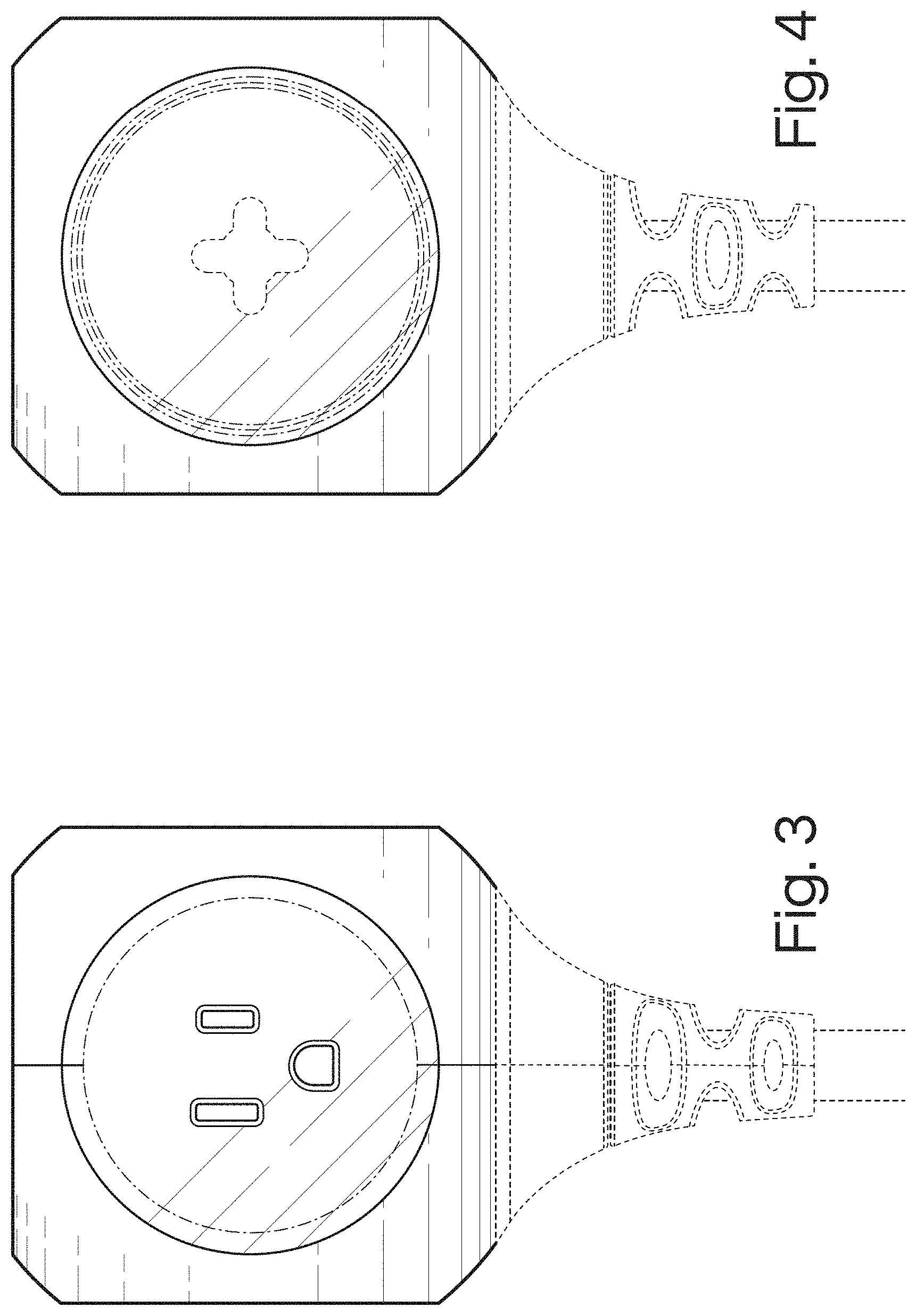
FIG. 3 is a left side elevation view thereof;
FIG. 4 is a bottom plan view thereof;
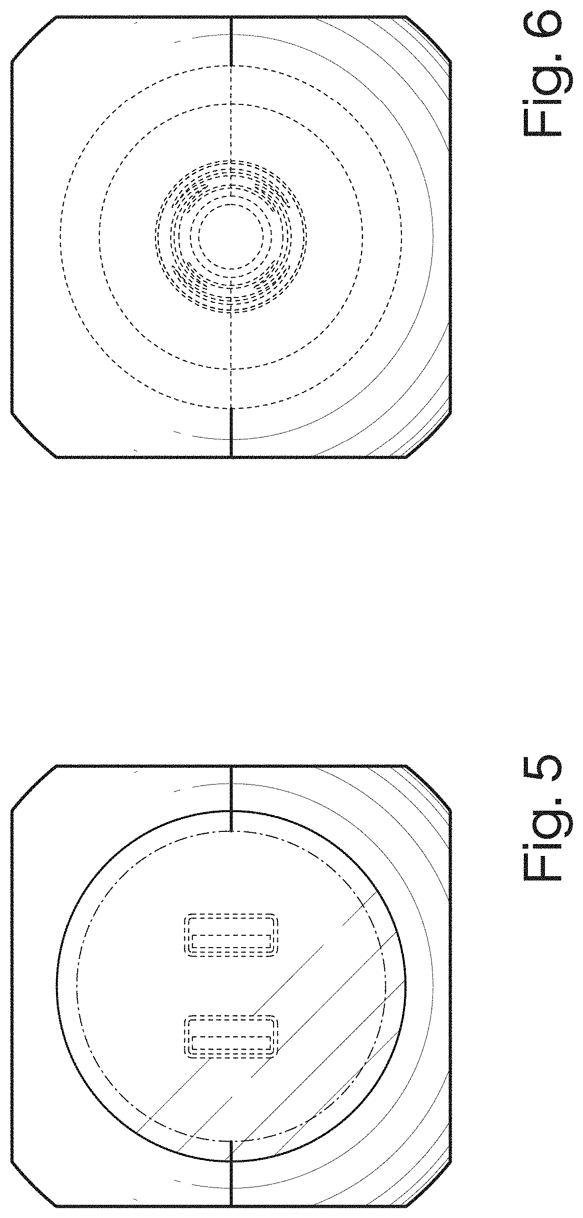
FIG. 5 is a front elevation view thereof;
FIG. 6 is a rear elevation view thereof;
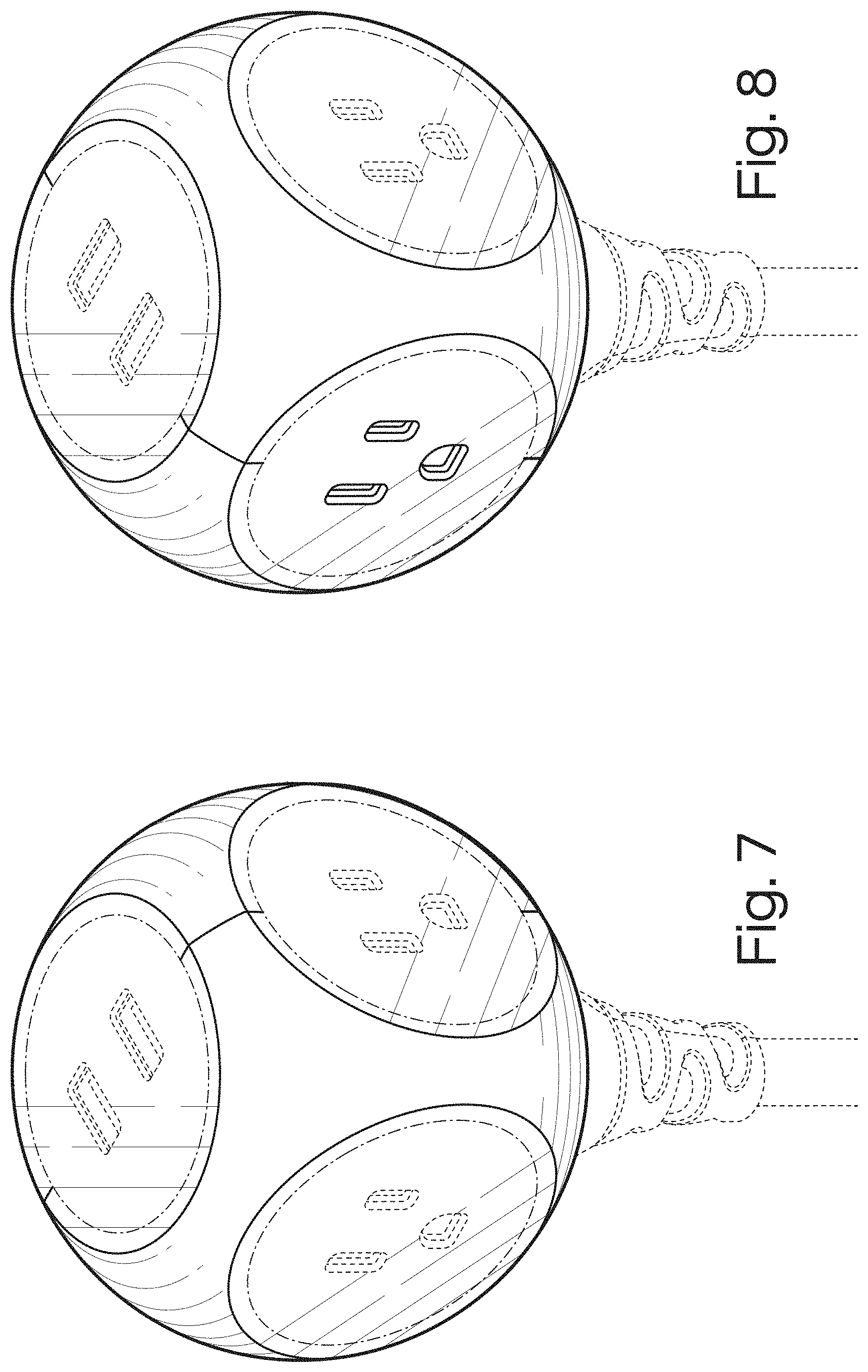
FIG. 7 is a first upper perspective view thereof;
FIG. 8 is a second upper perspective view thereof;
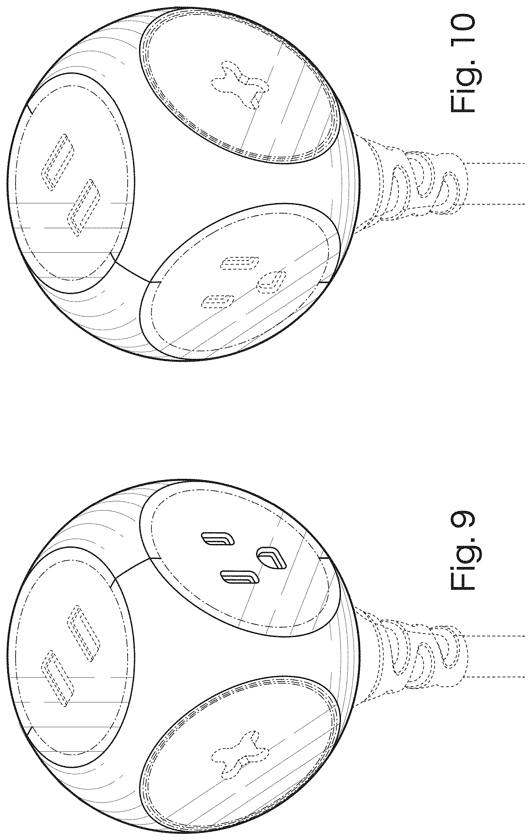
FIG. 9 is a third upper perspective view thereof;
FIG. 10 is a fourth upper perspective view thereof;
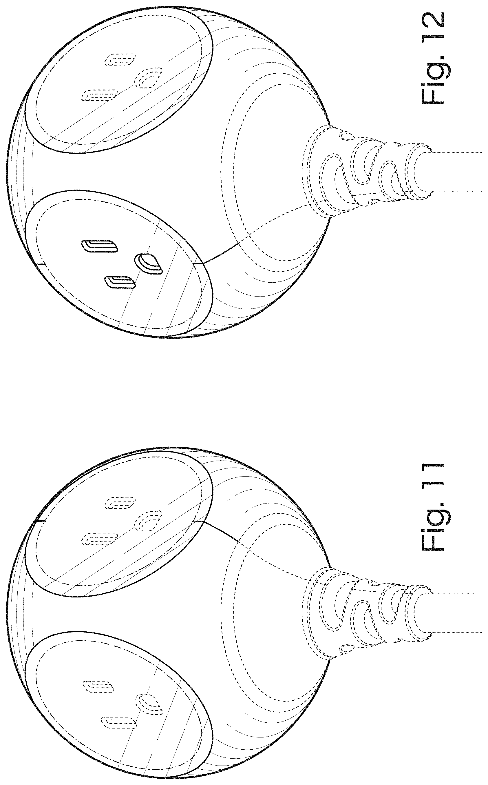
FIG. 11 is a first lower perspective view thereof;
FIG. 12 is a second lower perspective view thereof;
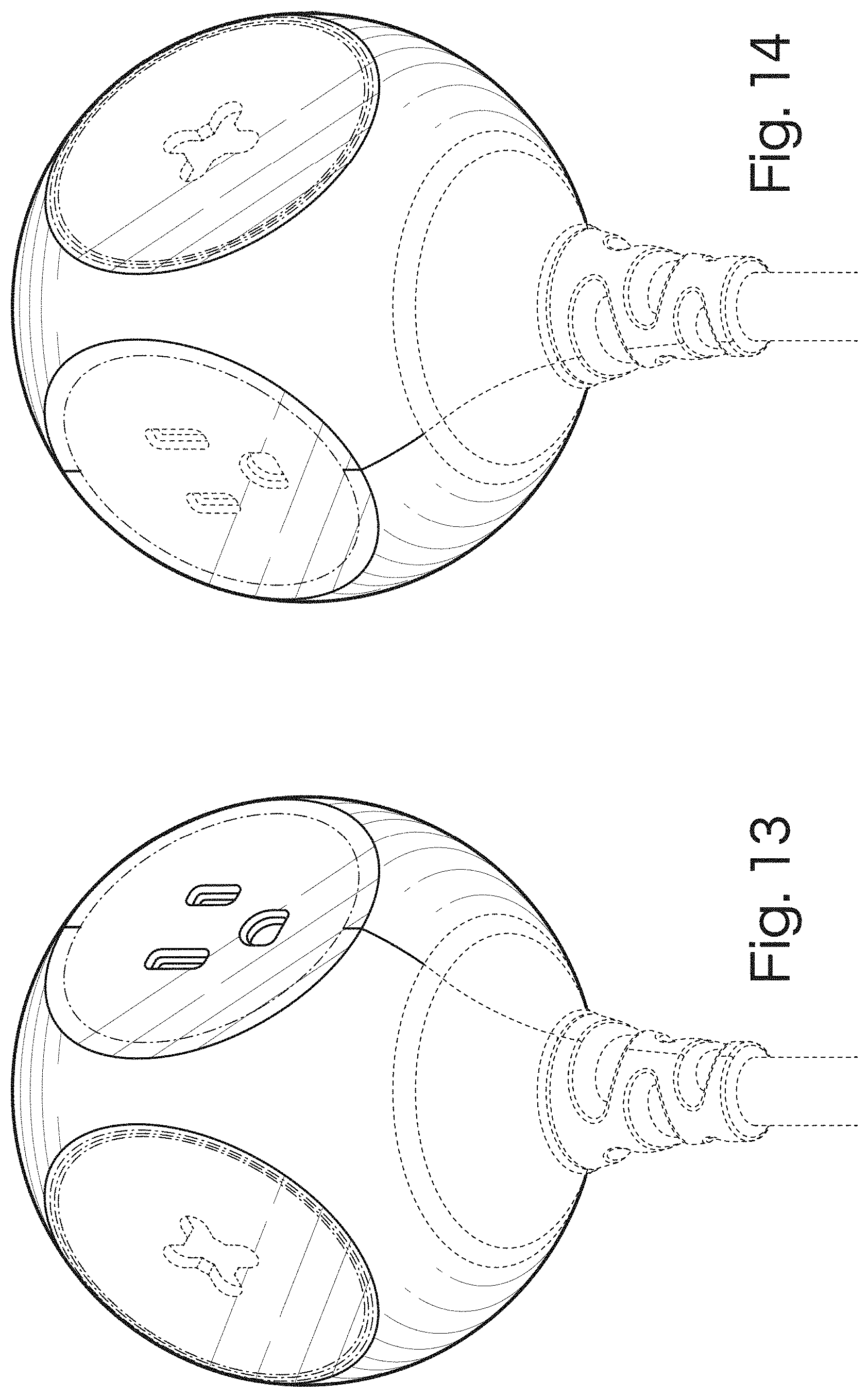
FIG. 13 is a third lower perspective view thereof; and,
FIG. 14 is a fourth lower perspective view thereof.
The dashed lines in the drawings are for the purpose of illustrating portions of the electrical extension cord receptacle end and environmental subject matter that form no part of the claimed design. The dot-dash lines are for the purpose of illustrating unclaimed seam lines on a claimed surface of the device. These seam lines form no part of the claimed design.
* * * * *
D00000
D00001
D00002
D00003
D00004
D00005
D00006
D00007
XML
uspto.report is an independent third-party trademark research tool that is not affiliated, endorsed, or sponsored by the United States Patent and Trademark Office (USPTO) or any other governmental organization. The information provided by uspto.report is based on publicly available data at the time of writing and is intended for informational purposes only.
While we strive to provide accurate and up-to-date information, we do not guarantee the accuracy, completeness, reliability, or suitability of the information displayed on this site. The use of this site is at your own risk. Any reliance you place on such information is therefore strictly at your own risk.
All official trademark data, including owner information, should be verified by visiting the official USPTO website at www.uspto.gov. This site is not intended to replace professional legal advice and should not be used as a substitute for consulting with a legal professional who is knowledgeable about trademark law.