Mobile device signal booster
Boggs , et al.
U.S. patent number D879,078 [Application Number D/625,667] was granted by the patent office on 2020-03-24 for mobile device signal booster. This patent grant is currently assigned to Wilson Electronics, LLC. The grantee listed for this patent is Wilson Electronics, LLC. Invention is credited to Joshua Boggs, Scot Herbst.


| United States Patent | D879,078 |
| Boggs , et al. | March 24, 2020 |
Mobile device signal booster
Claims
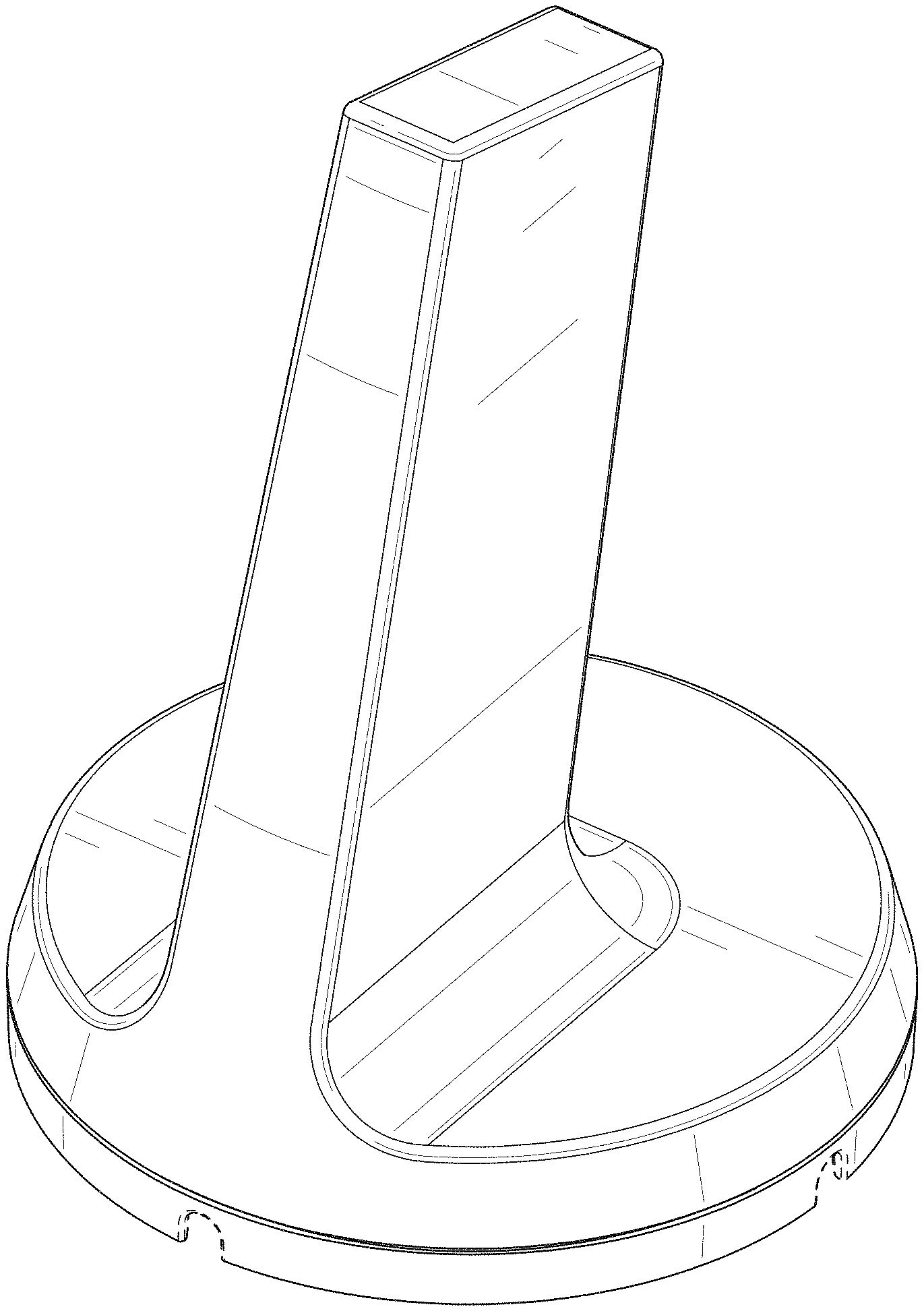
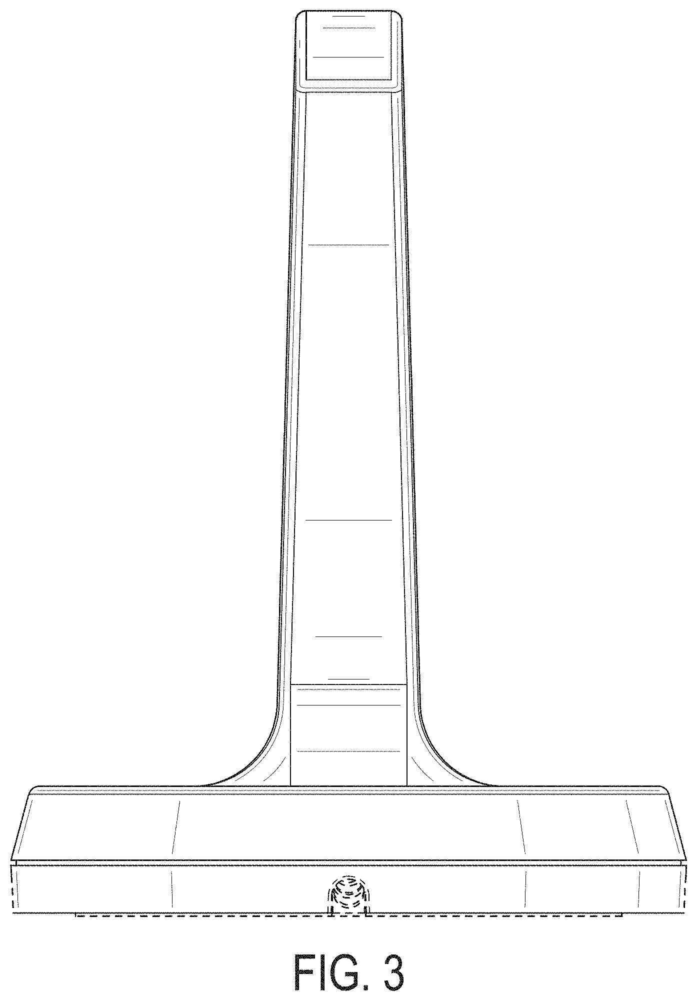
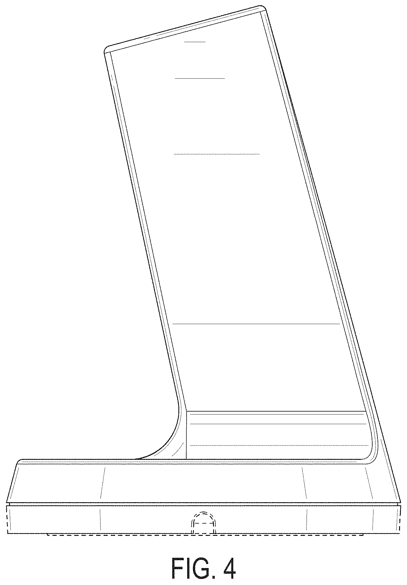
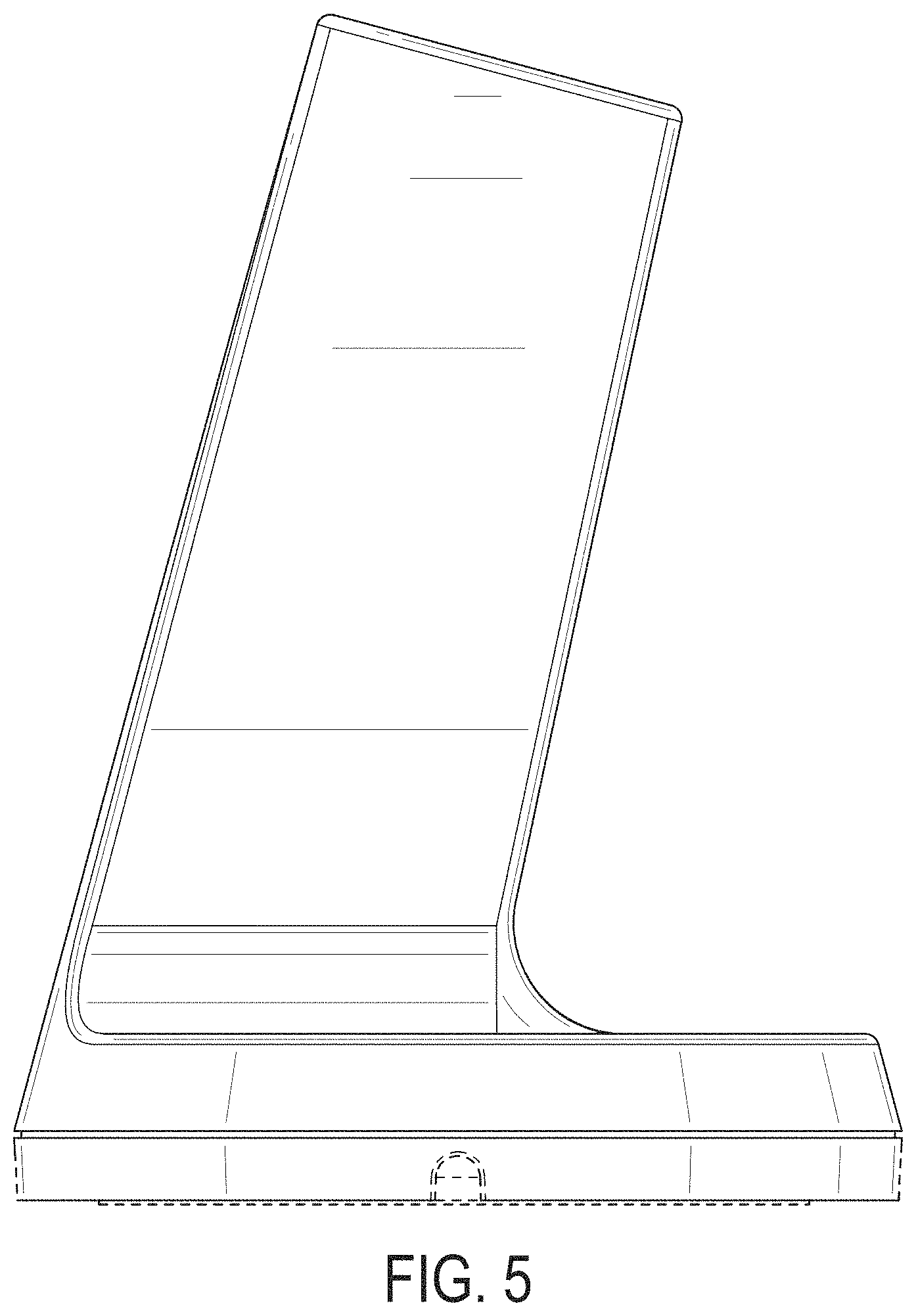
CLAIM The ornamental design for a mobile device signal booster, as shown and described.
| Inventors: | Boggs; Joshua (Aledo, TX), Herbst; Scot (Santa Cruz, CA) | ||||||||||
|---|---|---|---|---|---|---|---|---|---|---|---|
| Applicant: |
|
||||||||||
| Assignee: | Wilson Electronics, LLC (St.
George, UT) |
||||||||||
| Appl. No.: | D/625,667 | ||||||||||
| Filed: | November 10, 2017 |
| Current U.S. Class: | D14/230; D14/240 |
| Current International Class: | 1403 |
| Field of Search: | ;D14/230-238,138,172,188,203.1,203.3,203.6,204,216,221,238.1,240,242,299,314,343,356,358,496,509 ;D13/107,108 ;D12/42,43 |
References Cited [Referenced By]
U.S. Patent Documents
| D179162 | November 1956 | Sinko |
| D456351 | April 2002 | Yoneda |
| D461796 | August 2002 | Boyer |
| 7091912 | August 2006 | Iacovella |
| D542283 | May 2007 | Cislo |
| D542783 | May 2007 | Cislo |
| D544480 | June 2007 | Murakami |
| D546322 | July 2007 | Cislo |
| D550218 | September 2007 | Cislo |
| D551220 | September 2007 | Noro |
| D558190 | December 2007 | Cislo |
| D558764 | January 2008 | Kuo |
| D565534 | April 2008 | Ingalsbe |
| D573984 | July 2008 | Ferguson |
| D581403 | November 2008 | Zwingmann |
| D603375 | November 2009 | Jeong |
| 7639204 | December 2009 | Chau |
| D617319 | June 2010 | Maffetone |
| 7755551 | July 2010 | Lindackers |
| 8248315 | August 2012 | Lindackers |
| D684563 | June 2013 | Meek |
| D722964 | February 2015 | Regole |
Other References
|
"weBoost Drive Sleek 4G: Everything You Need to Know," weBoost Drive Sleek 4G Cell Phone Booster Outside Antenna pictured therein, YouTube online, post date Sep. 27, 2017, URL: https://www.youtube.com/watch?v=iUpIk-DmIbE, retrieved Jun. 19, 2018. cited by examiner. |
Primary Examiner: Asch; Jeffrey D
Assistant Examiner: Caruso; Rebekah A
Attorney, Agent or Firm: Jones Waldo Holbrook & McDonough, PC Winder; Brent T.
Description
FIG. 1 is a front perspective view of the presently claimed design.
FIG. 2 is a front view of the presently claimed design.
FIG. 3 is a rear view of the presently claimed design.
FIG. 4 is a side view of the presently claimed design.
FIG. 5 is an opposite side view of the presently claimed design.
FIG. 6 is a top view of the presently claimed design; and,
FIG. 7 is a bottom view of the presently claimed design.
The broken lines depict portions of the article that form no part of the claimed design.
* * * * *
References
D00000
D00001
D00002
D00003
D00004
D00005
D00006
D00007
XML
uspto.report is an independent third-party trademark research tool that is not affiliated, endorsed, or sponsored by the United States Patent and Trademark Office (USPTO) or any other governmental organization. The information provided by uspto.report is based on publicly available data at the time of writing and is intended for informational purposes only.
While we strive to provide accurate and up-to-date information, we do not guarantee the accuracy, completeness, reliability, or suitability of the information displayed on this site. The use of this site is at your own risk. Any reliance you place on such information is therefore strictly at your own risk.
All official trademark data, including owner information, should be verified by visiting the official USPTO website at www.uspto.gov. This site is not intended to replace professional legal advice and should not be used as a substitute for consulting with a legal professional who is knowledgeable about trademark law.