Pair of in-ear appliances
Madramotoo , et al.
U.S. patent number D877,720 [Application Number D/650,421] was granted by the patent office on 2020-03-10 for pair of in-ear appliances. This patent grant is currently assigned to EAROS, INC.. The grantee listed for this patent is Earos, Inc.. Invention is credited to John G. Aceti, Ronnie Andre Madramotoo, Peter Ragonetti, Wayne J. Staab, Francis George Tatu.


View All Diagrams
| United States Patent | D877,720 |
| Madramotoo , et al. | March 10, 2020 |
Pair of in-ear appliances
Claims
CLAIM The ornamental design for pair of in-ear appliances, as shown and described.
| Inventors: | Madramotoo; Ronnie Andre (New York, NY), Ragonetti; Peter (Brooklyn, NY), Staab; Wayne J. (Dammeron Valley, UT), Aceti; John G. (New Hope, PA), Tatu; Francis George (Somerset, NJ) | ||||||||||
|---|---|---|---|---|---|---|---|---|---|---|---|
| Applicant: |
|
||||||||||
| Assignee: | EAROS, INC. (New York,
NY) |
||||||||||
| Appl. No.: | D/650,421 | ||||||||||
| Filed: | June 6, 2018 |
| Current U.S. Class: | D14/223 |
| Current International Class: | 1401 |
| Field of Search: | ;D14/223,205 ;D24/174 ;128/864,865,866 ;181/129,130,135 ;379/430,431 ;381/380,381,324,312,322,334,330 ;455/90.3,575.1,569.1 |
References Cited [Referenced By]
U.S. Patent Documents
| D207206 | March 1967 | Geib |
| D298356 | November 1988 | Falco |
| D330761 | November 1992 | Falco |
| D479834 | September 2003 | Salazar |
| D480386 | October 2003 | Browne |
| D496653 | September 2004 | Townsend |
| D512990 | December 2005 | Yang |
| D536692 | February 2007 | Alwicker |
| D549222 | August 2007 | Huang |
| D550657 | September 2007 | Gan |
| D555150 | November 2007 | Christopher |
| D559836 | January 2008 | Lee |
| D595272 | June 2009 | Kim |
| D597084 | July 2009 | Gondo |
| D597534 | August 2009 | Christopher |
| D604722 | November 2009 | Mistry |
| D622855 | August 2010 | Cano, Jr. |
| D631470 | January 2011 | Yoneyama |
| D652822 | January 2012 | Lee |
| D658157 | April 2012 | McManigal |
| D666580 | September 2012 | Lee |
| D676026 | February 2013 | Lee |
| D684699 | June 2013 | Heaysman |
| D684700 | June 2013 | Heaysman |
| D685481 | July 2013 | Heaysman |
| D711356 | August 2014 | Yang |
| D728107 | April 2015 | Torres Martin |
| D742861 | November 2015 | Miyake |
| 9198800 | December 2015 | Killion |
| D764445 | August 2016 | Czaniecki |
| D767532 | September 2016 | Jen |
| D786216 | May 2017 | Silva |
| D788079 | May 2017 | Son |
| D799452 | October 2017 | Lee |
| D801950 | November 2017 | Otani |
| D806879 | January 2018 | Horbinski |
| D808360 | January 2018 | Arimoto |
| D812042 | March 2018 | Xiao |
| D813205 | March 2018 | Palmborg |
| D817309 | May 2018 | Czaniecki |
| D822646 | July 2018 | Dang |
| D824359 | July 2018 | Czaniecki |
| D827616 | September 2018 | Lian |
| D841626 | February 2019 | Tang |
| D842844 | March 2019 | Li |
| D843354 | March 2019 | Kumano |
| D845932 | April 2019 | Lu |
| D846532 | April 2019 | Xiao |
| D847126 | April 2019 | Loermann |
| 2009/0304220 | December 2009 | Fujikura |
| 2013/0259286 | October 2013 | Chung |
| 2017/0026738 | January 2017 | Tang |
Attorney, Agent or Firm: Cooley LLP
Description
FIG. 1A is a front view of a left in-ear appliance of a pair of in-ear appliances showing a first embodiment of our new design;
FIG. 1B is a front view of a right in-ear appliance of the pair of in-ear appliances showing the first embodiment of our new design;
FIG. 2A is a rear view of the left in-ear appliance of the first embodiment;
FIG. 2B is a rear view of the right in-ear appliance of the first embodiment;
FIG. 3A is a side view of the left in-ear appliance of the first embodiment;
FIG. 3B is a side view of the right in-ear appliance of the first embodiment;
FIG. 4A is a top view of the left in-ear appliance of the first embodiment;
FIG. 4B is a top view of the right in-ear appliance of the first embodiment;
FIG. 5A is a bottom view of the left in-ear appliance of the first embodiment;
FIG. 5B is a bottom view of the right in-ear appliance of the first embodiment;
FIG. 6A is a top rear perspective view of the left in-ear appliance of the first embodiment;
FIG. 6B is a top rear perspective view of the right in-ear appliance of the first embodiment;
FIG. 7A is a top front perspective view of the left in-ear appliance of the first embodiment;
FIG. 7B is a top front perspective view of the right in-ear appliance of the first embodiment;
FIG. 8A is a front view of a left in-ear appliance of a pair of in-ear appliances showing a second embodiment of our new design;
FIG. 8B is a front view of a right in-ear appliance of the pair of in-ear appliances showing the second embodiment of our new design;
FIG. 9A is a back view of the left in-ear appliance of the second embodiment;
FIG. 9B is a back view of the right in-ear appliance of the second embodiment;
FIG. 10A is a side view of the left in-ear appliance of the second embodiment;
FIG. 10B is a side view of the right in-ear appliance of the second embodiment;
FIG. 11A is a top view of the left in-ear appliance of the second embodiment;
FIG. 11B is a top view of the right in-ear appliance of the second embodiment;
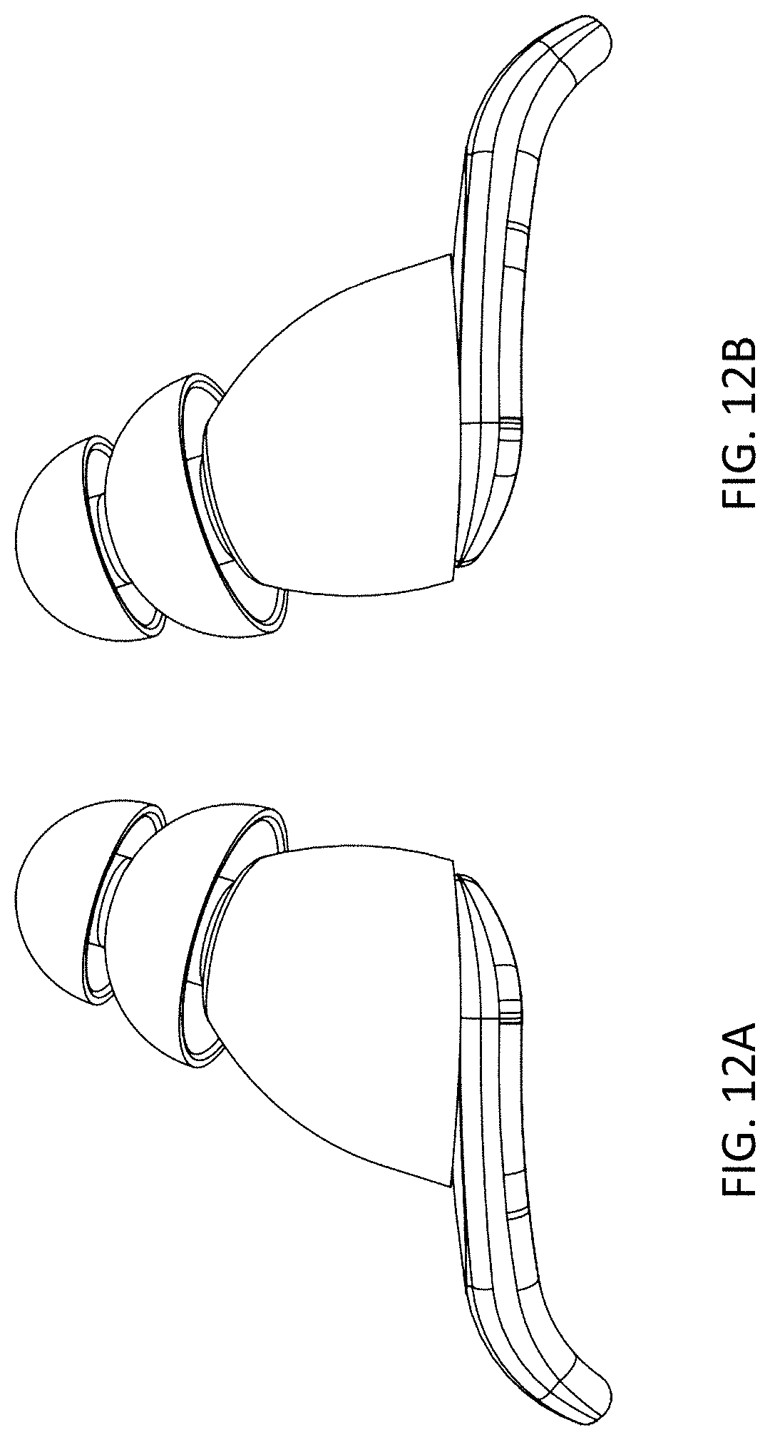
FIG. 12A is a bottom view of the left in-ear appliance of the second embodiment;
FIG. 12B is a bottom view of the right in-ear appliance of the second embodiment;
FIG. 13A is a top rear perspective view of the left in-ear appliance of the second embodiment;
FIG. 13B is a top rear perspective view of the right in-ear appliance of the second embodiment;
FIG. 14A is a top front perspective view of the left in-ear appliance of the second embodiment; and,
FIG. 14B is a top front perspective view of the right in-ear appliance of the second embodiment.
* * * * *
D00000
D00001
D00002
D00003
D00004
D00005
D00006
D00007
D00008
D00009
D00010
D00011
D00012
D00013

D00014

XML
uspto.report is an independent third-party trademark research tool that is not affiliated, endorsed, or sponsored by the United States Patent and Trademark Office (USPTO) or any other governmental organization. The information provided by uspto.report is based on publicly available data at the time of writing and is intended for informational purposes only.
While we strive to provide accurate and up-to-date information, we do not guarantee the accuracy, completeness, reliability, or suitability of the information displayed on this site. The use of this site is at your own risk. Any reliance you place on such information is therefore strictly at your own risk.
All official trademark data, including owner information, should be verified by visiting the official USPTO website at www.uspto.gov. This site is not intended to replace professional legal advice and should not be used as a substitute for consulting with a legal professional who is knowledgeable about trademark law.