Vehicle cup holder cell phone mount
MacNeil , et al.
U.S. patent number D877,043 [Application Number D/707,213] was granted by the patent office on 2020-03-03 for vehicle cup holder cell phone mount. This patent grant is currently assigned to MACNEIL IP LLC. The grantee listed for this patent is MacNeil IP LLC. Invention is credited to David S. Iverson, David F. MacNeil.


View All Diagrams
| United States Patent | D877,043 |
| MacNeil , et al. | March 3, 2020 |
Vehicle cup holder cell phone mount
Claims
CLAIM We claim the ornamental design for a vehicle cup holder cell phone mount, as shown and described.
| Inventors: | MacNeil; David F. (Fort Lauderdale, FL), Iverson; David S. (Oak Brook, IL) | ||||||||||
|---|---|---|---|---|---|---|---|---|---|---|---|
| Applicant: |
|
||||||||||
| Assignee: | MACNEIL IP LLC (Bolingbrook,
IL) |
||||||||||
| Appl. No.: | D/707,213 | ||||||||||
| Filed: | September 26, 2019 |
Related U.S. Patent Documents
| Application Number | Filing Date | Patent Number | Issue Date | ||
|---|---|---|---|---|---|
| 29668090 | Oct 26, 2018 | ||||
| Current U.S. Class: | D12/415 |
| Current International Class: | 1216 |
| Field of Search: | ;D12/415-420,400,191,195,106,345,96,99,223,114 ;D14/253,251,252,447,451,452,440,434,458,432,439,457,460,238.1,140,142,149,217,148,140.8,140.11,209.1,151,140.9 ;D13/107,108 ;D7/523,529-536,507-512,300,300.1,591,608,629,630,500-502 |
References Cited [Referenced By]
U.S. Patent Documents
| D247548 | March 1978 | Crary |
| D289898 | May 1987 | Miller |
| D309307 | July 1990 | Sigurdson |
| D402666 | December 1998 | Golder |
| D407408 | March 1999 | Hoff |
| 6062518 | May 2000 | Etue |
| 6246766 | June 2001 | Walsh |
| D451504 | December 2001 | Edwards |
| D452236 | December 2001 | Kohli |
| D475044 | May 2003 | Kohli |
| 7099467 | August 2006 | Rohrbach |
| 7140586 | November 2006 | Seil |
| D558769 | January 2008 | Krieger |
| D625715 | October 2010 | Adams, II |
| D654119 | February 2012 | Lin |
| D655282 | March 2012 | Richter |
| D705211 | May 2014 | Huang |
| D709066 | July 2014 | Byun |
| D718298 | November 2014 | Aspinall |
| 9079545 | July 2015 | Dugan |
| D771614 | November 2016 | Chang |
| D777720 | January 2017 | Russell |
| D799469 | October 2017 | Esses |
| D807701 | January 2018 | Bo |
| D817317 | May 2018 | Lee |
| 9987993 | June 2018 | Thorimbert |
| D823062 | July 2018 | Goodwin |
| D832248 | October 2018 | Sukphist |
| D833369 | November 2018 | Lan |
| D835113 | December 2018 | Kim |
| D848412 | May 2019 | Greve |
| D848443 | May 2019 | Yao |
| D859395 | September 2019 | Yao |
| 2014/0176062 | June 2014 | Jung |
| 106427807 | Feb 2017 | CN | |||
Other References
|
Macally Cell Phone Cup Holder for Car Mount, Amazon.com, Date First Available: Jun. 29, 2017, [online], [site visited Oct. 24, 2019]. <URL: https://www.amazon.com/Macally-Samsung-Motorola-Smartphones-MCUP- /dp/B002JTWRN8> (Year: 2017). cited by examiner . Cellet PH600 Car Cup Holder Mount, Amazon.com, [online], [site visited Oct. 24, 2019]. <URL: https://www.amazon.com/dp/B006BIQBMQ/ref=psdc_2230642011_t4_B002JTWRN8>- ; (Year: 2019). cited by examiner . 10 Cup Holder Phone Mount Reviews for 2019, HotRate.com, by Joey Randall, Last Updated Jan. 25, 2019, [online], [site visited Oct. 24, 2019]. <URL: https://www.hotrate.com/electronics/cup-holder-phone-mount/> (Year: 2019). cited by examiner . amazon.com, website, image of Belkin Car Cup Holder for Smartphones, downloaded on Jan. 17, 2019. cited by applicant . amazon.com, website, image of Custom Accessories 23384 Heavy Cup Mount Magnetic Phone Holder, downloaded on Jan. 17, 2019. cited by applicant . amazon.com, website, image of Macally Adjustable Automobile Cup Holder Phone Mount, downloaded on Jan. 17, 2019. cited by applicant . amazon.com, website, image of Mediabridge Smartphone Cradle w/Extended Cup Holder Mount, downloaded on Jan. 17, 2019. cited by applicant . amazon.com, website, image of NNDA CO Universal Adjustable Gooseneck Cup Holder Cradle Car Mount for Phone, downloaded on Jan. 17, 2019. cited by applicant . amazon.com, website, image of Sunjoyco Car Cup Holder Mount for Phone Tablet, 2-in-1 Car Cradles Adjustable Gooseneck Holder, downloaded on Jan. 17, 2019. cited by applicant . amazon.com, website, image of Tackform Solutions Car Phone Holder Magnetic Mount, downloaded on Jan. 17, 2019. cited by applicant . amazon.com, website, image of TNP Cup Holder Phone Mount, Universal Car Cup Smartphone Cradle Clamp w/ Flexible Neck, downloaded on Jan. 17, 2019. cited by applicant . amazon.com, website, image of USA Gear Cup Holder Suction Mount Surface Adapter, downloaded on Jan. 17, 2019. cited by applicant . crutchfield.com, website, image of Bracketron BT 16572 PhabGrip cup holder mount, downloaded on Jan. 17, 2019. cited by applicant . HDAccessory.com, website, image of Universal Smartphone Cup Holder Mount, downloaded on Jan. 17, 2019. cited by applicant . stacksocial.com, website, image of U-Grip Cup Holder Car Mount for Phones and Tablets, downloaded on Jan. 17, 2019. cited by applicant . walmart.com, website, image of Universal Adjustable Gooseneck Cup Holder Cradle Car Mount for Cell Phone, downloaded on Jan. 17, 2019. cited by applicant . rakuten.com, website, image of Smartphone 8'' Long Car Cup Holder, IKross Phone Mount, downloaded on Jan. 17, 2019. cited by applicant. |
Primary Examiner: Nelson; T Chase
Assistant Examiner: Han; Jonathan J.
Attorney, Agent or Firm: Perkins IP Law Group LLC Perkins; Jefferson
Description
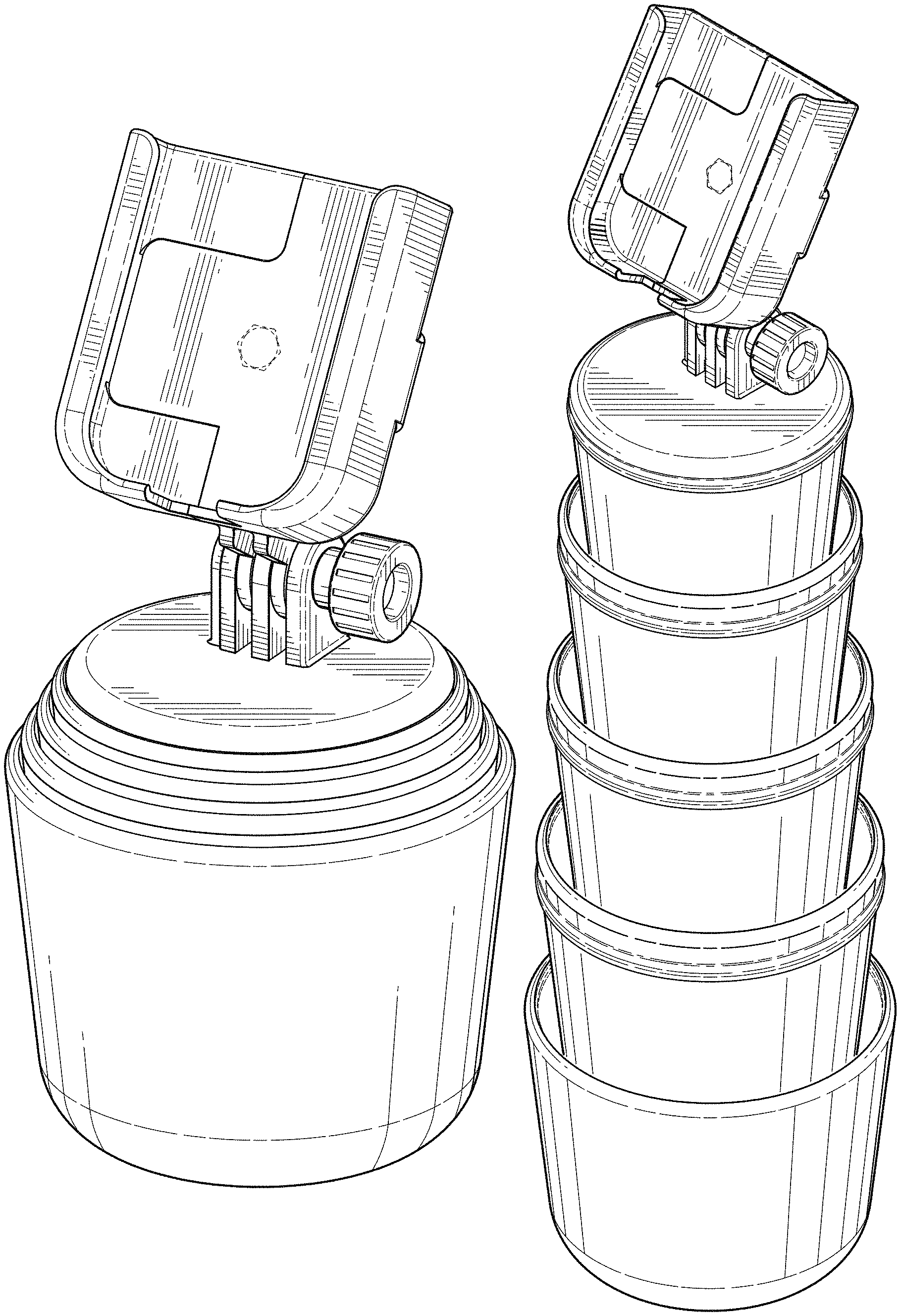
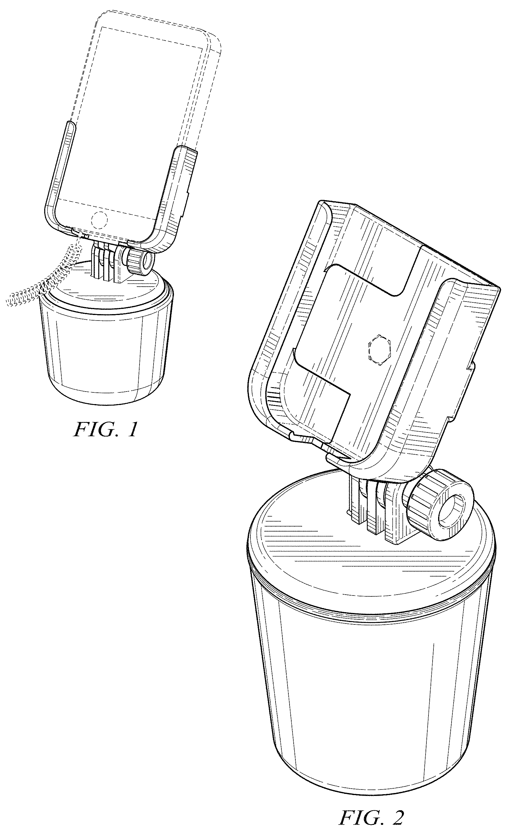
FIG. 1 is a top front perspective view of a first configuration of our design in which two of four shells of our design have been assembled to a base of our design, a cell phone and power cord being shown in dotted line as environmental structure;
FIG. 2 is front top perspective view of a second configuration of our design, in which jaws of a cell phone mounting bracket of our design are in a fully closed position, and in which no shells of our design have been assembled to the base;
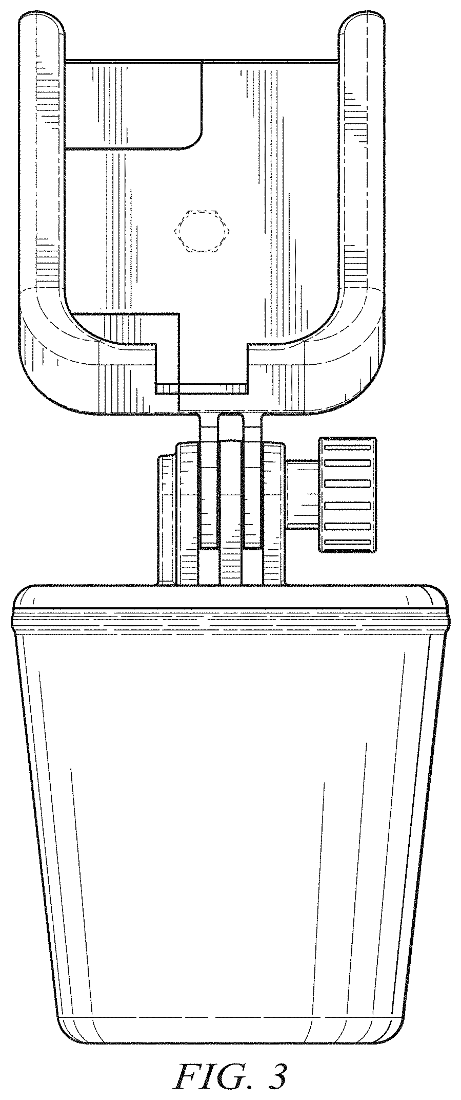
FIG. 3 is a front view of our design as configured in FIG. 2;
FIG. 4 is a right side view of our design as configured in FIG. 2;
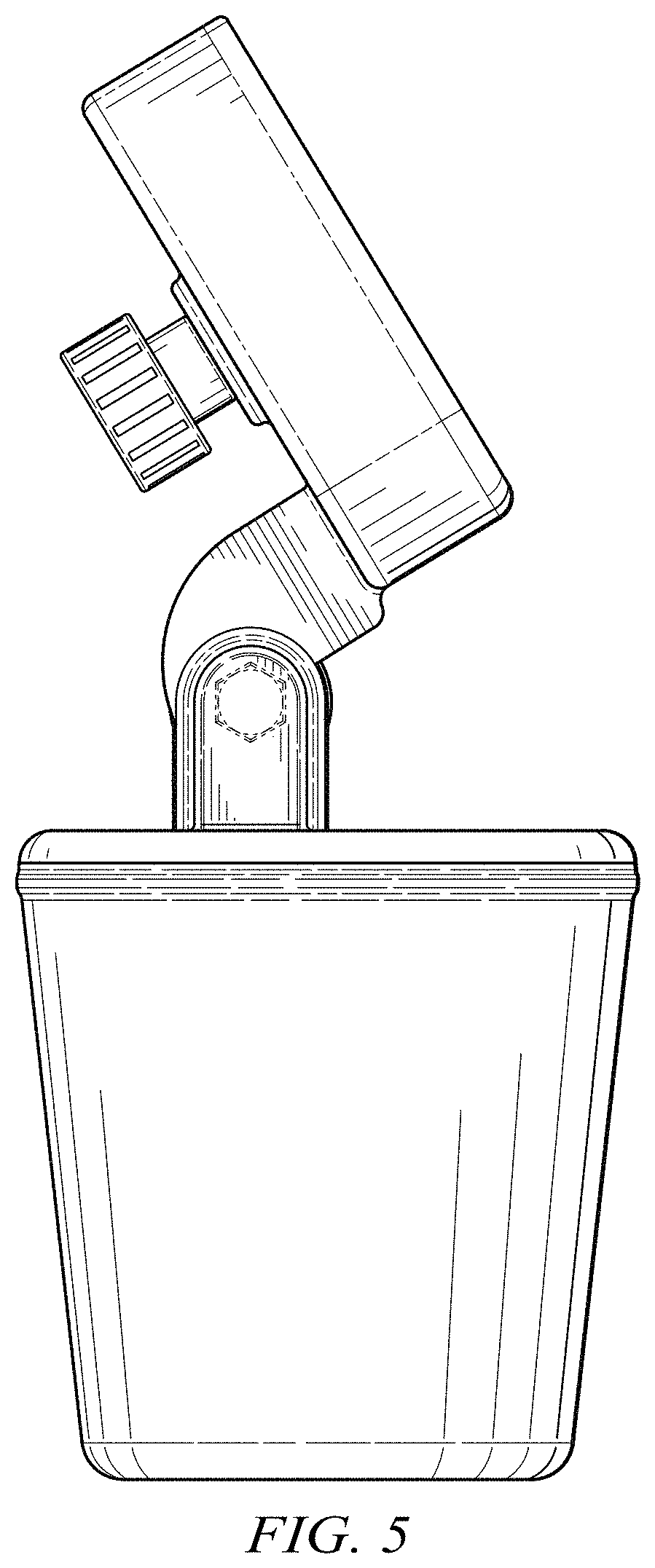
FIG. 5 is a left side view of our design as configured in FIG. 2;
FIG. 6 is a rear view of our design as configured in FIG. 2;
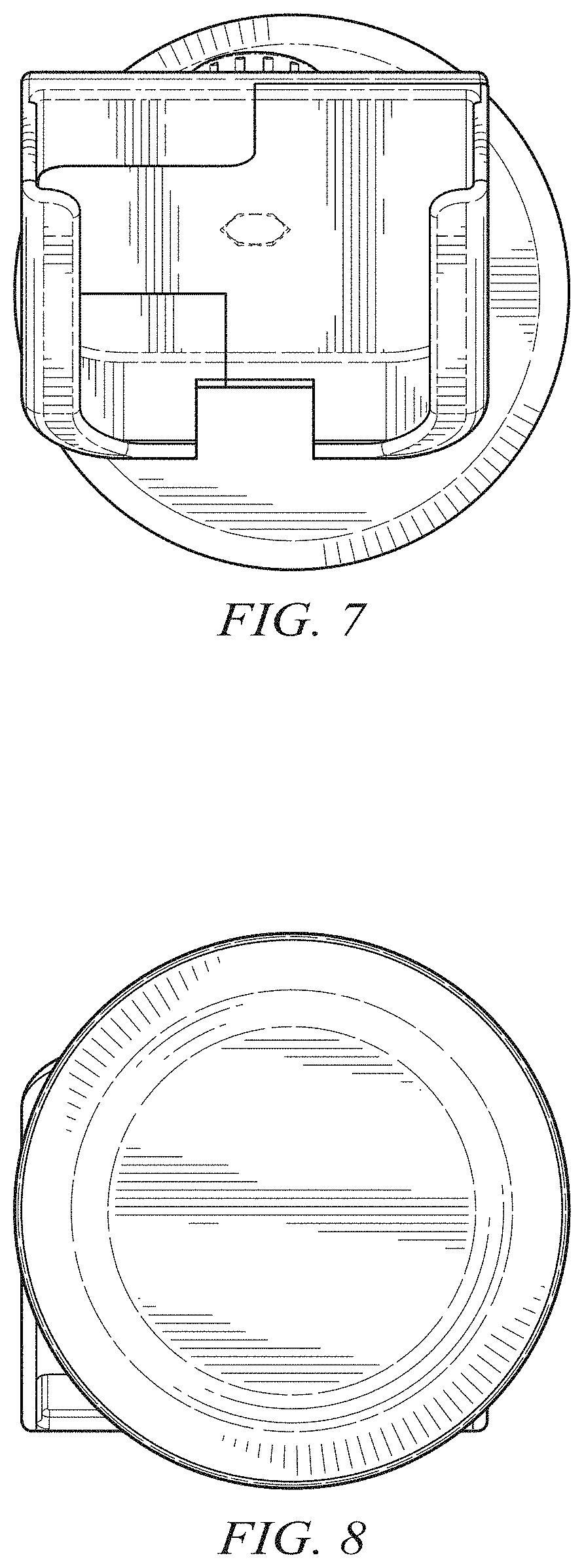
FIG. 7 is a top view of our design as configured in FIG. 2;
FIG. 8 is a bottom view of our design as configured in FIG. 2;
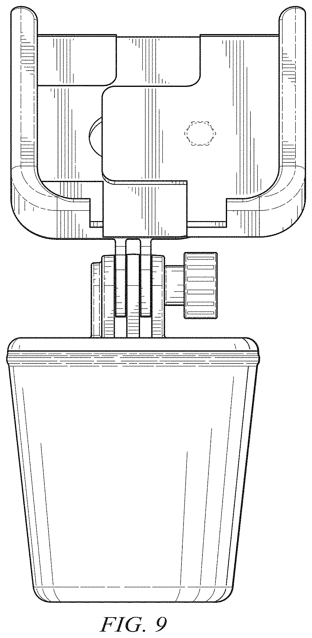
FIG. 9 is a front view of a third configuration of our design, in which no shells have been assembled to the base, and in which the jaws of the mounting bracket are in a fully open position;
FIG. 10 is a top front perspective view of a fourth configuration of our design, in which first, second, third and fourth shells have been assembled to the base and in which the jaws of the mounting bracket are in a fully closed position;
FIG. 11 is a front view of our design as configured in FIG. 10;
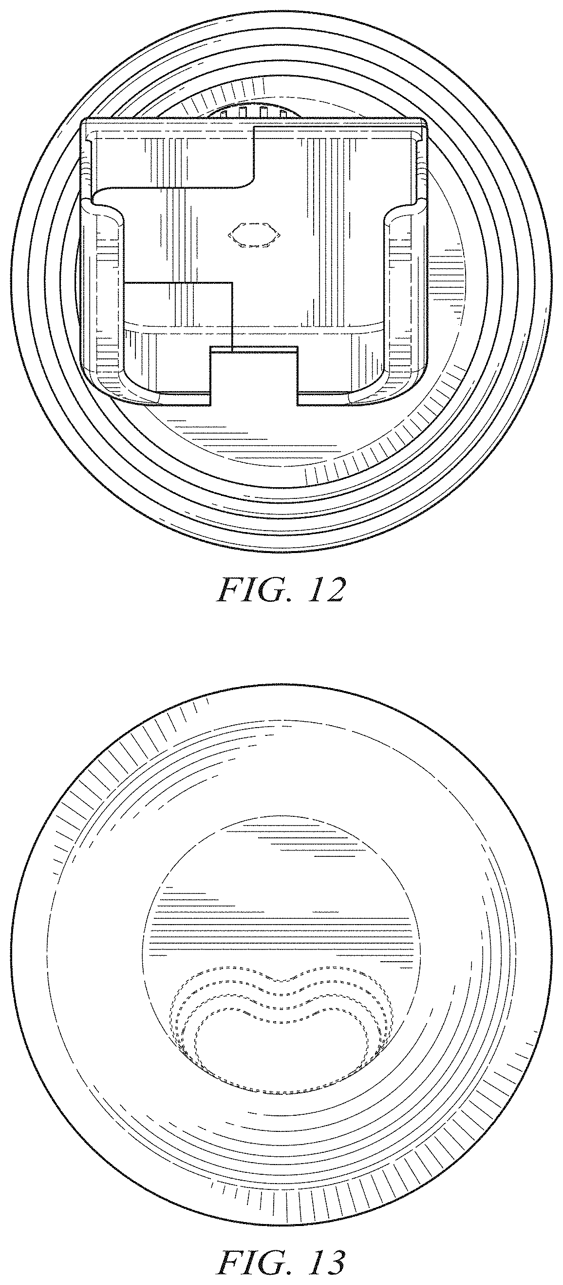
FIG. 12 is a top view of our design as configured in FIG. 10;
FIG. 13 is a bottom view of our design as configured in FIG. 10;
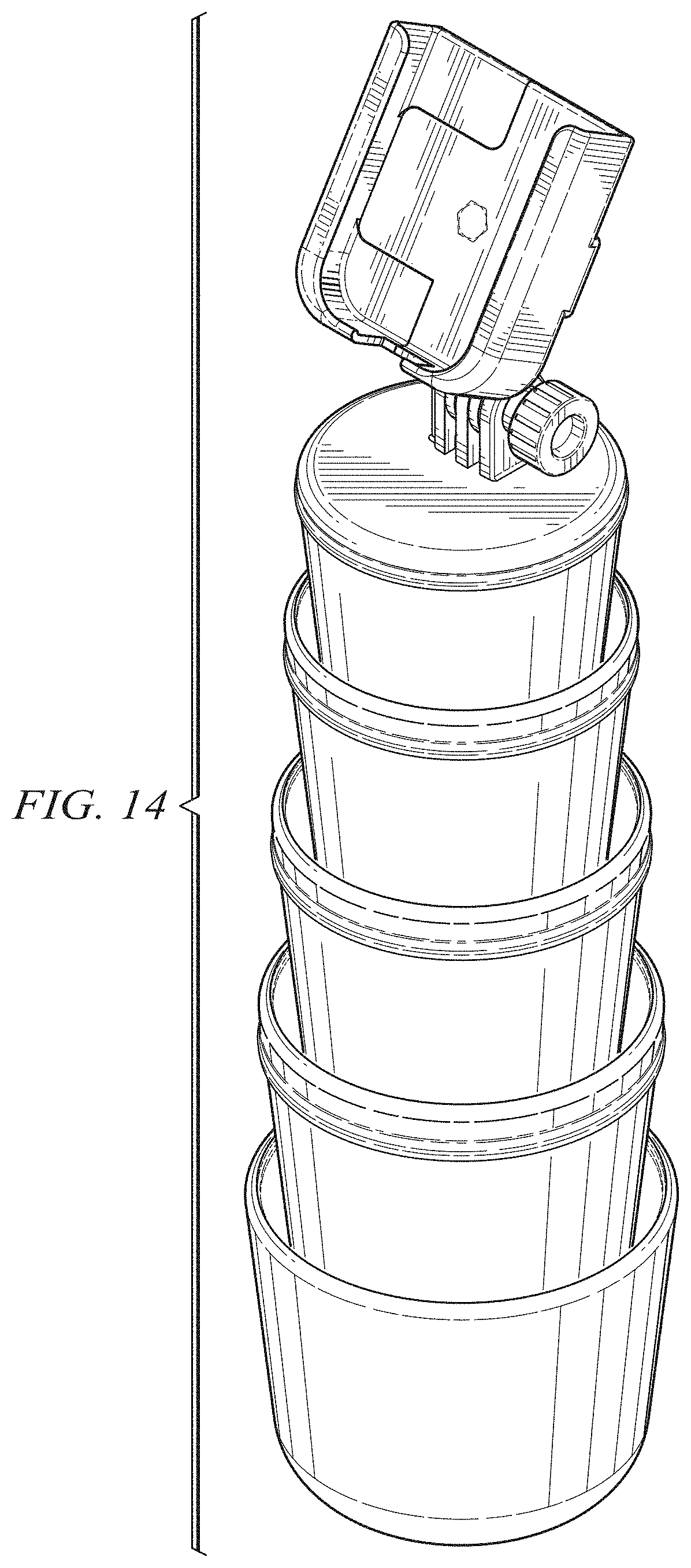
FIG. 14 is a top front exploded perspective view of our design as configured in FIG. 10;
FIG. 15 is a bottom rear exploded perspective view of our design as configured in FIG. 10;
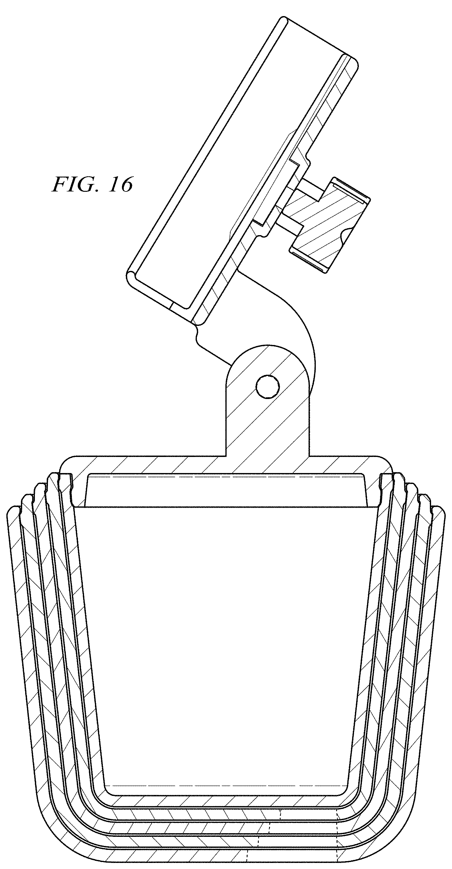
FIG. 16 is a front-to-rear axial sectional view of our design as configured in FIG. 10;
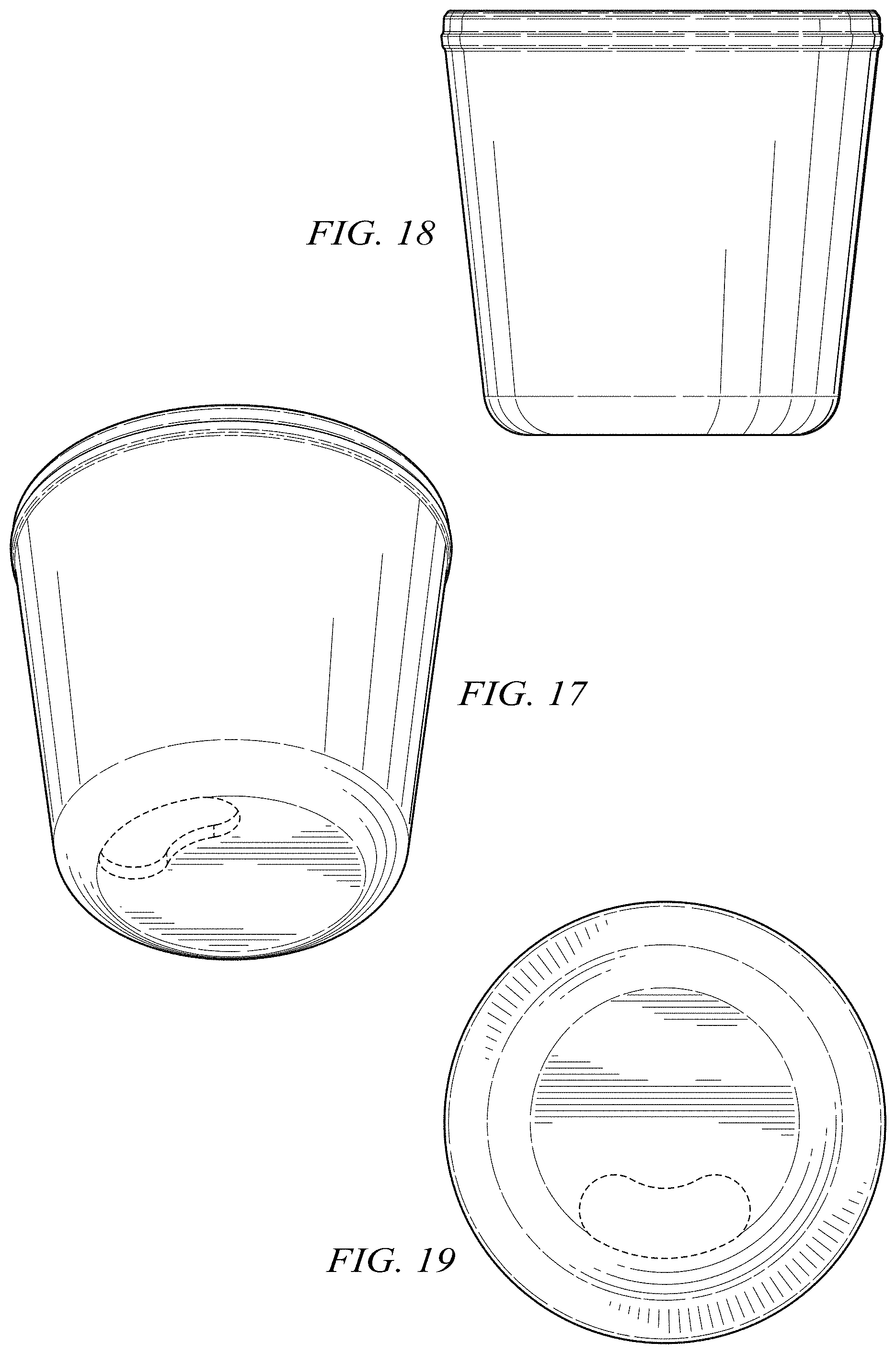
FIG. 17 is a bottom perspective view of a first shell forming a portion of our design;
FIG. 18 is a side view of the first shell;
FIG. 19 is a bottom view of the first shell;
FIG. 20 is a top view of the first shell;
FIG. 21 is a top perspective view of the first shell;
FIG. 22 is a partial sectional detail of the lip region of the first shell taken along 22-22 in FIG. 21;
FIG. 23 is a bottom perspective view of a second shell forming a portion of our design;
FIG. 24 is a side view of the second shell;
FIG. 25 is bottom view of the second shell;
FIG. 26 is a top view of the second shell;
FIG. 27 is a top perspective view of the second shell;
FIG. 28 is a partial sectional detail of the lip region of the second shell taken along 28-28 in FIG. 27;
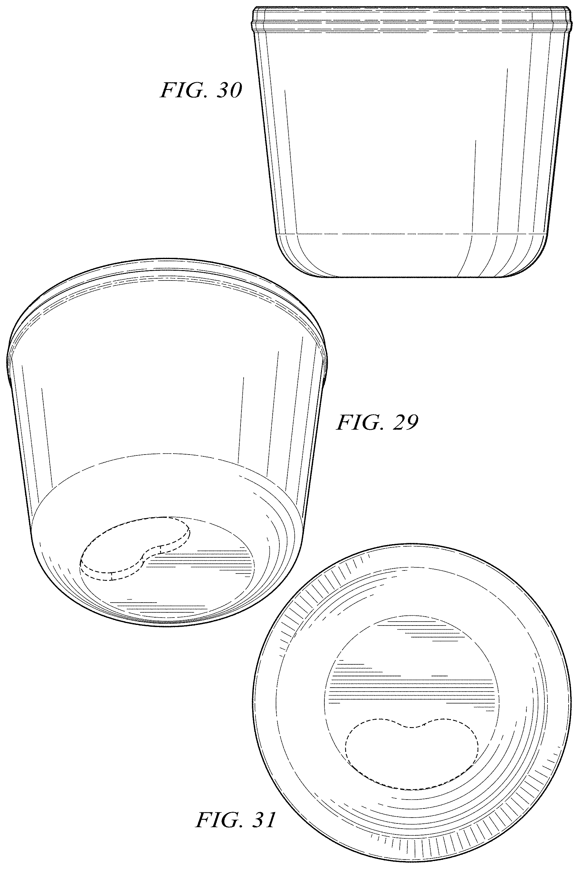
FIG. 29 is a bottom perspective view of a third shell forming a portion of our design;
FIG. 30 is a side view of the third shell;
FIG. 31 is bottom view of the shell;
FIG. 32 is a top view of the third shell;
FIG. 33 is a top perspective view of the third shell;
FIG. 34 is a partial sectional detail of the lip region of the third shell taken along 34-34 in FIG. 33;
FIG. 35 is a bottom perspective view of a fourth shell forming a portion of our design;
FIG. 36 is a side view of the fourth shell;
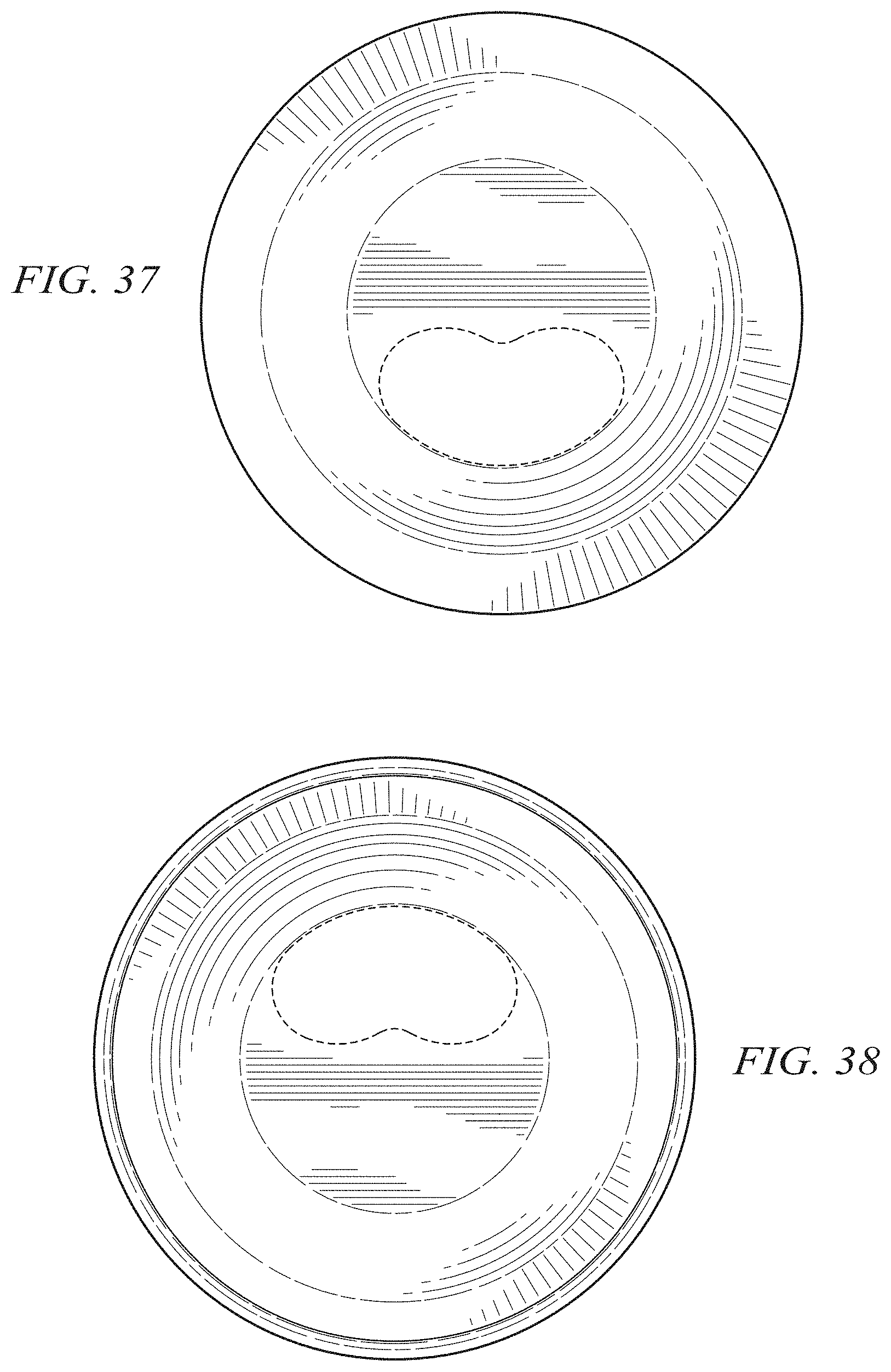
FIG. 37 is bottom view of the fourth shell;
FIG. 38 is a top view of the fourth shell;
FIG. 39 is a top perspective view of the fourth shell; and,
FIG. 40 is a partial sectional detail of the lip region of the fourth shell taken along 40-40 in FIG. 39.
The dotted lines shown in the drawings illustrate environment and portions of the vehicle cup holder cell phone mount that form no part of the claimed design.
* * * * *
References
D00000
D00001
D00002
D00003
D00004
D00005
D00006
D00007
D00008
D00009
D00010
D00011
D00012

D00013
D00014
D00015

D00016

D00017

D00018
D00019

D00020

D00021
D00022

XML
uspto.report is an independent third-party trademark research tool that is not affiliated, endorsed, or sponsored by the United States Patent and Trademark Office (USPTO) or any other governmental organization. The information provided by uspto.report is based on publicly available data at the time of writing and is intended for informational purposes only.
While we strive to provide accurate and up-to-date information, we do not guarantee the accuracy, completeness, reliability, or suitability of the information displayed on this site. The use of this site is at your own risk. Any reliance you place on such information is therefore strictly at your own risk.
All official trademark data, including owner information, should be verified by visiting the official USPTO website at www.uspto.gov. This site is not intended to replace professional legal advice and should not be used as a substitute for consulting with a legal professional who is knowledgeable about trademark law.