Projectile for ammunition
Marin , et al. Feb
U.S. patent number D876,578 [Application Number D/629,659] was granted by the patent office on 2020-02-25 for projectile for ammunition. The grantee listed for this patent is Quantum Ammunition, LLC. Invention is credited to Paul Lemke, Juan Carlos Marin, Kyle Adam Masinelli, Connor McDermott.


| United States Patent | D876,578 |
| Marin , et al. | February 25, 2020 |
Projectile for ammunition
Claims
CLAIM The ornamental design for projectile for ammunition, as shown and described.
| Inventors: | Marin; Juan Carlos (Girona, ES), Lemke; Paul (Savannah, GA), Masinelli; Kyle Adam (Oxford, MS), McDermott; Connor (Abbeville, MS) | ||||||||||
|---|---|---|---|---|---|---|---|---|---|---|---|
| Applicant: |
|
||||||||||
| Appl. No.: | D/629,659 | ||||||||||
| Filed: | December 14, 2017 |
| Current U.S. Class: | D22/116 |
| Current International Class: | 2203 |
| Field of Search: | ;D21/301,304,567,570,571,573,574,575,746 ;D22/100,101,102,103,106,107,108,109,110,111,112,115,116,199 |
References Cited [Referenced By]
U.S. Patent Documents
| 4251079 | February 1981 | Earl |
| 5133261 | July 1992 | Kelsey, Jr. |
| 6692083 | February 2004 | Latham |
| 7526998 | May 2009 | Vasel |
| 8192310 | June 2012 | Harris |
| 8789470 | July 2014 | Frank |
| D732635 | June 2015 | Riley |
| D733834 | July 2015 | Burczynski |
| D735289 | July 2015 | Burczynski |
| D748220 | January 2016 | Fricke |
| D752702 | March 2016 | Arnedo Vera |
| D752703 | March 2016 | Arnedo Vera |
| D753258 | April 2016 | Arnedo Vera |
| 9354027 | May 2016 | Flint |
| D759781 | June 2016 | Hagan |
| D764624 | August 2016 | Masinelli |
| D765215 | August 2016 | Gibson |
| D775305 | December 2016 | Fiocchi |
| D780282 | February 2017 | Riley |
| D781993 | March 2017 | Schultz |
| D782601 | March 2017 | Riley |
| D782602 | March 2017 | Riley |
| 9709368 | July 2017 | Mahnke |
| 9829293 | November 2017 | Fricke |
| D813974 | March 2018 | Peterson |
| 2002/0100389 | August 2002 | May |
| 2006/0027128 | February 2006 | Hober |
| 2007/0074637 | April 2007 | Pontieri |
| 2007/0151474 | July 2007 | Widener |
| 2016/0047638 | February 2016 | Golloher |
| 2016/0231093 | August 2016 | Lemke |
Other References
|
"Inceptor ARX Ammo from PolyCase Ammunition: Guns & Gear|S7" [online]. Gun Talk Media. [Published on Sep. 29, 2015]. Retrieved from the Internet: <https://www.youtube.com/watch?v=Bs1ecdqQW1U>. cited by examiner. |
Primary Examiner: Anwar; Khawaja
Assistant Examiner: Tehrani; Mojtaba
Attorney, Agent or Firm: Withers & Keys, LLC
Description
FIG. 1 is a perspective side view of the projectile for ammunition showing our new design;
FIG. 2 is a side bottom perspective view thereof;
FIG. 3 is a front elevation view thereof;
FIG. 4 is a rear elevation view thereof;
FIG. 5 is a top plan view thereof;
FIG. 6 is a bottom plan view thereof;
FIG. 7 is a left side elevation view thereof; and,
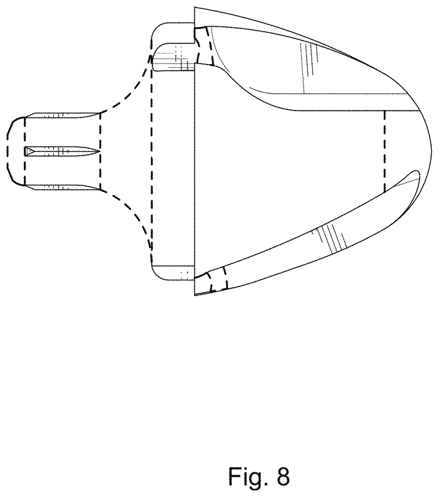
FIG. 8 is a right side elevation view thereof.
The dashed broken lines shown in the drawings illustrate portions of the projectile for ammunition that forms no part of the claimed design.
Non-shaded surfaces within the claimed boundary form no part of the claimed design.
* * * * *
References
D00000
D00001
D00002
D00003
D00004
D00005
D00006
D00007
D00008
XML
uspto.report is an independent third-party trademark research tool that is not affiliated, endorsed, or sponsored by the United States Patent and Trademark Office (USPTO) or any other governmental organization. The information provided by uspto.report is based on publicly available data at the time of writing and is intended for informational purposes only.
While we strive to provide accurate and up-to-date information, we do not guarantee the accuracy, completeness, reliability, or suitability of the information displayed on this site. The use of this site is at your own risk. Any reliance you place on such information is therefore strictly at your own risk.
All official trademark data, including owner information, should be verified by visiting the official USPTO website at www.uspto.gov. This site is not intended to replace professional legal advice and should not be used as a substitute for consulting with a legal professional who is knowledgeable about trademark law.