Inline pressure sensor and electrical connector
Bivans , et al. Feb
U.S. patent number D875,583 [Application Number D/692,702] was granted by the patent office on 2020-02-18 for inline pressure sensor and electrical connector. This patent grant is currently assigned to BAXTER HEALTHCARE SA, BAXTER INTERNATIONAL INC.. The grantee listed for this patent is Baxter Healthcare SA, Baxter International Inc.. Invention is credited to Matthew Alan Bivans, Karl Hans Cazzini, Keerthika Lakshmi Niharika Chinthapalli, Sarah Louise Corbin, William R. Griswold, Jonathan A. Handler, Ulf Quensel, Julia Radchenko, Andrea Frances Ritchie, Timothy Brian Sanchez, Jonathan Toback.


| United States Patent | D875,583 |
| Bivans , et al. | February 18, 2020 |
Inline pressure sensor and electrical connector
Claims
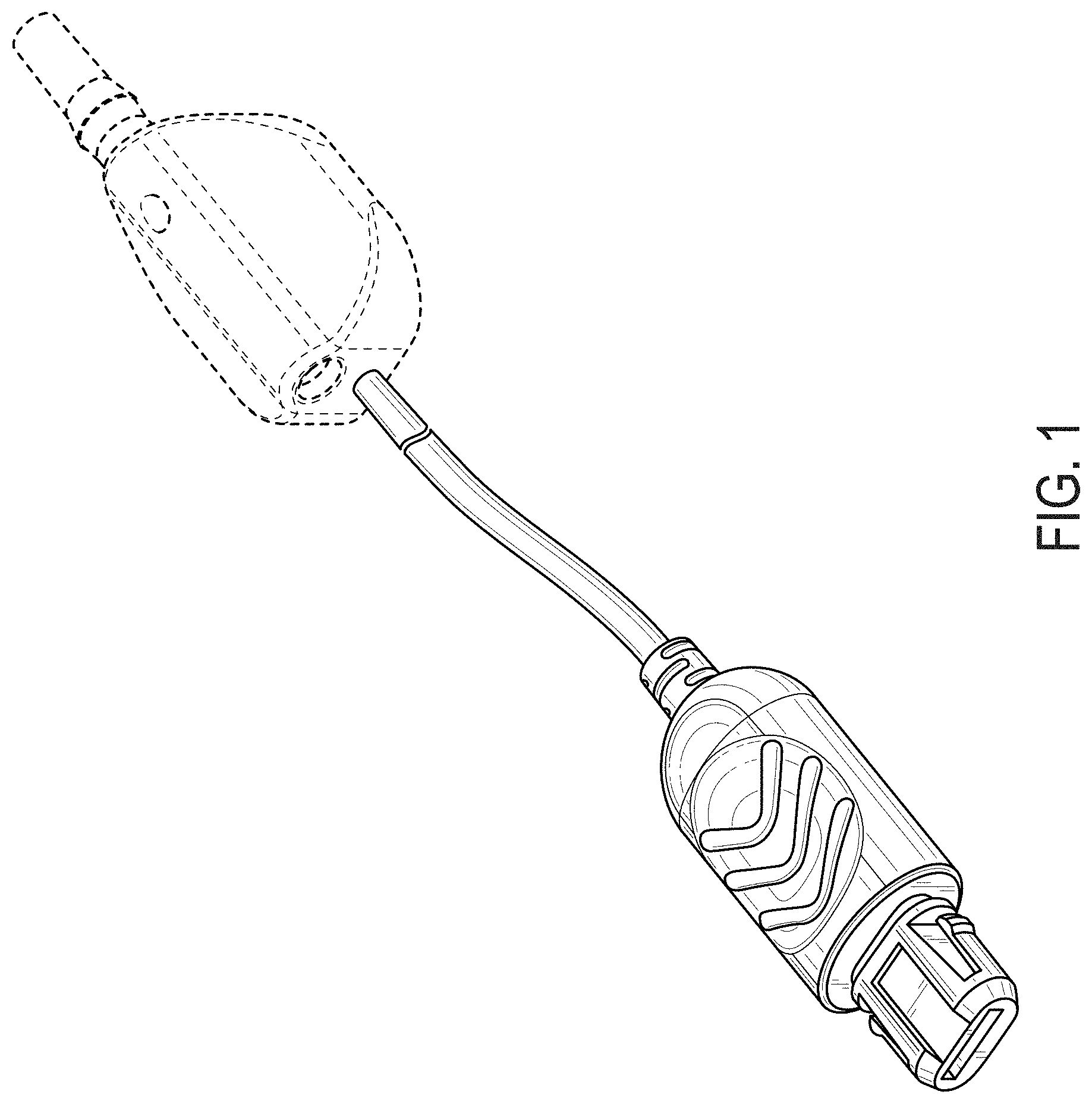
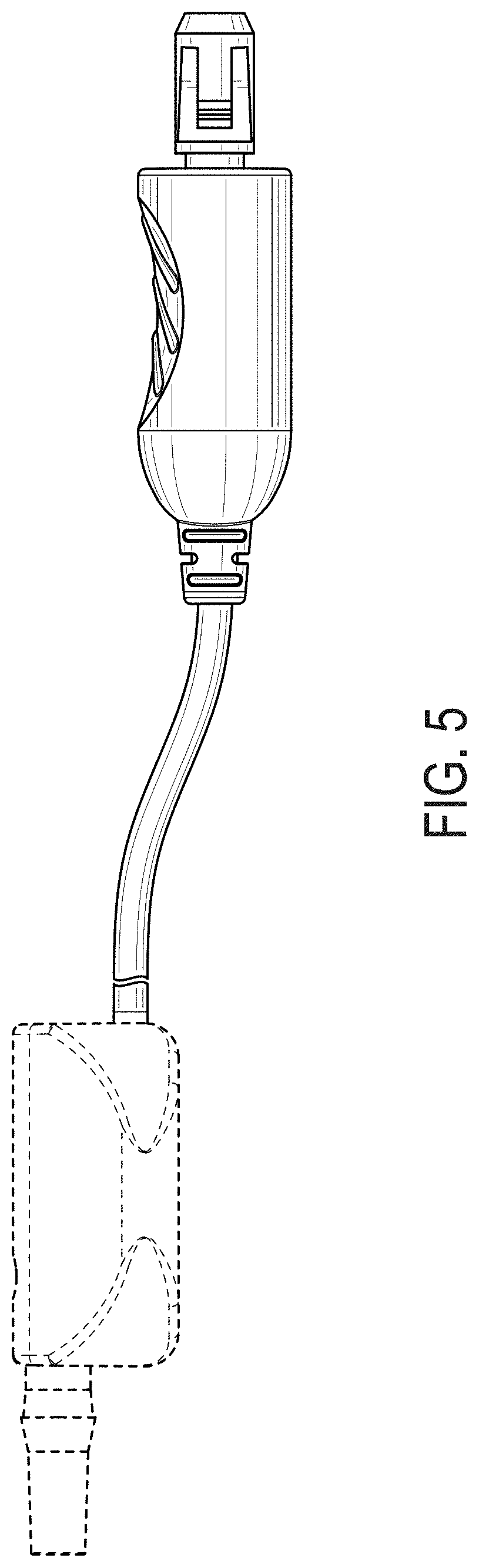
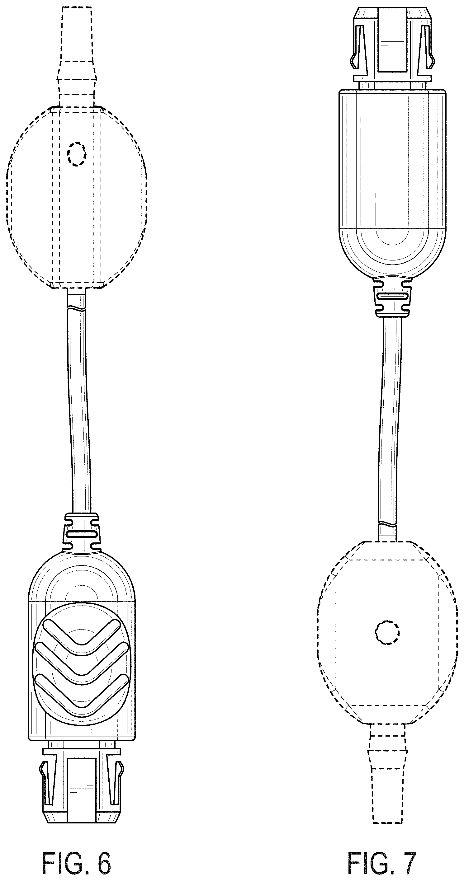
CLAIM The ornamental design for an inline pressure sensor and electrical connector, as shown and described herein.
| Inventors: | Bivans; Matthew Alan (Barrington, IL), Griswold; William R. (Lake Geneva, WI), Cazzini; Karl Hans (Lindenhurst, IL), Toback; Jonathan (Chicago, IL), Chinthapalli; Keerthika Lakshmi Niharika (Round Lake, IL), Radchenko; Julia (Buffalo Grove, IL), Corbin; Sarah Louise (Hawthorn Woods, IL), Ritchie; Andrea Frances (Alameda, CA), Sanchez; Timothy Brian (Chicago, IL), Quensel; Ulf (Ystad, SE), Handler; Jonathan A. (Northbrook, IL) | ||||||||||
|---|---|---|---|---|---|---|---|---|---|---|---|
| Applicant: |
|
||||||||||
| Assignee: | BAXTER INTERNATIONAL INC.
(Deerfield, IL) BAXTER HEALTHCARE SA (Glattpark (Opfikon), CH) |
||||||||||
| Appl. No.: | D/692,702 | ||||||||||
| Filed: | May 28, 2019 |
Related U.S. Patent Documents
| Application Number | Filing Date | Patent Number | Issue Date | ||
|---|---|---|---|---|---|
| 29647517 | May 14, 2018 | ||||
| Current U.S. Class: | D10/85; D24/186 |
| Current International Class: | 1004 |
| Field of Search: | ;D10/85 ;D24/186 |
References Cited [Referenced By]
U.S. Patent Documents
| D840357 | February 2019 | Zhao |
Attorney, Agent or Firm: K&L Gates LLP
Description
FIG. 1 illustrates a perspective view of an electrical connector embodying the invention.
FIG. 2 illustrates a front view of the electrical connector shown in FIG. 1.
FIG. 3 illustrates a rear view of the electrical connector shown in FIG. 1.
FIG. 4 illustrates a right side view of the electrical connector shown in FIG. 1.
FIG. 5 illustrates a left side view of the electrical connector shown in FIG. 1.
FIG. 6 illustrates a top view of the electrical connector shown in FIG. 1; and,
FIG. 7 illustrates a bottom view of the electrical connector shown in FIG. 1.
* * * * *
D00000
D00001
D00002
D00003
D00004
D00005
XML
uspto.report is an independent third-party trademark research tool that is not affiliated, endorsed, or sponsored by the United States Patent and Trademark Office (USPTO) or any other governmental organization. The information provided by uspto.report is based on publicly available data at the time of writing and is intended for informational purposes only.
While we strive to provide accurate and up-to-date information, we do not guarantee the accuracy, completeness, reliability, or suitability of the information displayed on this site. The use of this site is at your own risk. Any reliance you place on such information is therefore strictly at your own risk.
All official trademark data, including owner information, should be verified by visiting the official USPTO website at www.uspto.gov. This site is not intended to replace professional legal advice and should not be used as a substitute for consulting with a legal professional who is knowledgeable about trademark law.