Shelf pin hole jig
Clark J
U.S. patent number D871,880 [Application Number D/649,040] was granted by the patent office on 2020-01-07 for shelf pin hole jig. This patent grant is currently assigned to KREG ENTERPRISES, INC.. The grantee listed for this patent is KREG ENTERPRISES, INC.. Invention is credited to Scott L. Clark.


| United States Patent | D871,880 |
| Clark | January 7, 2020 |
Shelf pin hole jig
Claims
CLAIM The ornamental design for a shelf pin hole jig having a plurality of guide channels, as is shown and described.
| Inventors: | Clark; Scott L. (Boone, IA) | ||||||||||
|---|---|---|---|---|---|---|---|---|---|---|---|
| Applicant: |
|
||||||||||
| Assignee: | KREG ENTERPRISES, INC. (Huxley,
IA) |
||||||||||
| Family ID: | 46600726 | ||||||||||
| Appl. No.: | D/649,040 | ||||||||||
| Filed: | May 25, 2018 |
Related U.S. Patent Documents
| Application Number | Filing Date | Patent Number | Issue Date | ||
|---|---|---|---|---|---|
| 14074476 | Nov 7, 2013 | ||||
| 13020277 | Nov 11, 2014 | 8882409 | |||
| Current U.S. Class: | D8/71 |
| Current CPC Class: | B23B49/02 20130101; B23B49/023 20130101; B23B47/287 20130101; B25H3/003 20130101; Y10T408/569 20150115; Y10T408/98 20150115; Y10T408/03 20150115; Y10T408/97 20150115; Y10T408/567 20150115 |
| Current International Class: | 0805 |
| Field of Search: | ;D8/70 ;D10/61,64,65 ;D15/138,140 |
References Cited [Referenced By]
U.S. Patent Documents
| 4474514 | October 1984 | Jensen |
| D282626 | February 1986 | Zelli |
| D293203 | December 1987 | Hertensteiner |
| 4719951 | January 1988 | Woltanski |
| D295016 | April 1988 | Forrester |
| 4952101 | August 1990 | Coombs |
| 5056966 | October 1991 | Lee |
| D328698 | August 1992 | Worthington |
| D357854 | May 1995 | Payne |
| D363201 | October 1995 | Hill |
| 5560408 | October 1996 | DiFranco |
| D380953 | July 1997 | Norgaard |
| D393217 | April 1998 | Brickman |
| D393218 | April 1998 | Brickman |
| 5853270 | December 1998 | Salley |
| D431440 | October 2000 | Okada |
| D568706 | May 2008 | Weiby |
| D568707 | May 2008 | Weiby |
| 8152420 | April 2012 | Block |
| D679613 | April 2013 | Propp |
| 8459906 | June 2013 | Schmitt |
| D688930 | September 2013 | Krohmer |
| D690180 | September 2013 | Del Rossa |
| D701542 | March 2014 | Shearer |
| D718595 | December 2014 | Shearer |
| D734680 | July 2015 | Eisinger |
| D804927 | December 2017 | Ryan |
| D824741 | August 2018 | Davis |
| 2009/0191015 | July 2009 | Quinn |
| 2010/0320162 | December 2010 | Kao |
| 2012/0243955 | September 2012 | Cross |
| 2014/0064868 | March 2014 | Clark |
| 2015/0016907 | January 2015 | Frick |
Attorney, Agent or Firm: Proskey; Christopher A. BrownWinick Law Firm
Description
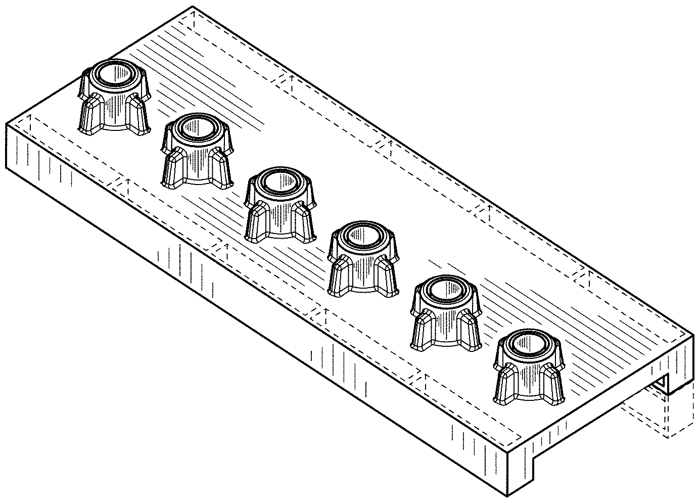
FIG. 1 is a top, front, and left side perspective view of a shelf pin hole jig showing my new design;
FIG. 2 is a left side elevation view thereof;
FIG. 3 is a right side elevation view thereof;
FIG. 4 is a front elevation view thereof;
FIG. 5 is a rear elevation view thereof;
FIG. 6 is a top plan view thereof;
FIG. 7 is a bottom plan view thereof; and,
FIG. 8 is a top, rear, and right side perspective view thereof with the guide accessory exploded apart.
The broken lines in the drawings illustrate portions of the shelf pin hole jig that form no part of the claimed design.
* * * * *
D00000
D00001
D00002
D00003
D00004
D00005
D00006
XML
uspto.report is an independent third-party trademark research tool that is not affiliated, endorsed, or sponsored by the United States Patent and Trademark Office (USPTO) or any other governmental organization. The information provided by uspto.report is based on publicly available data at the time of writing and is intended for informational purposes only.
While we strive to provide accurate and up-to-date information, we do not guarantee the accuracy, completeness, reliability, or suitability of the information displayed on this site. The use of this site is at your own risk. Any reliance you place on such information is therefore strictly at your own risk.
All official trademark data, including owner information, should be verified by visiting the official USPTO website at www.uspto.gov. This site is not intended to replace professional legal advice and should not be used as a substitute for consulting with a legal professional who is knowledgeable about trademark law.