Sphygmomanometer with electrocardiograph
Hirasawa , et al. Dec
U.S. patent number D871,582 [Application Number D/654,417] was granted by the patent office on 2019-12-31 for sphygmomanometer with electrocardiograph. This patent grant is currently assigned to OMRON HEALTHCARE Co., Ltd.. The grantee listed for this patent is OMRON HEALTHCARE Co., Ltd.. Invention is credited to Asa Hirasawa, Kosuke Inoue, Kengo Nishiyama, Tsuyoshi Ogihara.


| United States Patent | D871,582 |
| Hirasawa , et al. | December 31, 2019 |
Sphygmomanometer with electrocardiograph
Claims
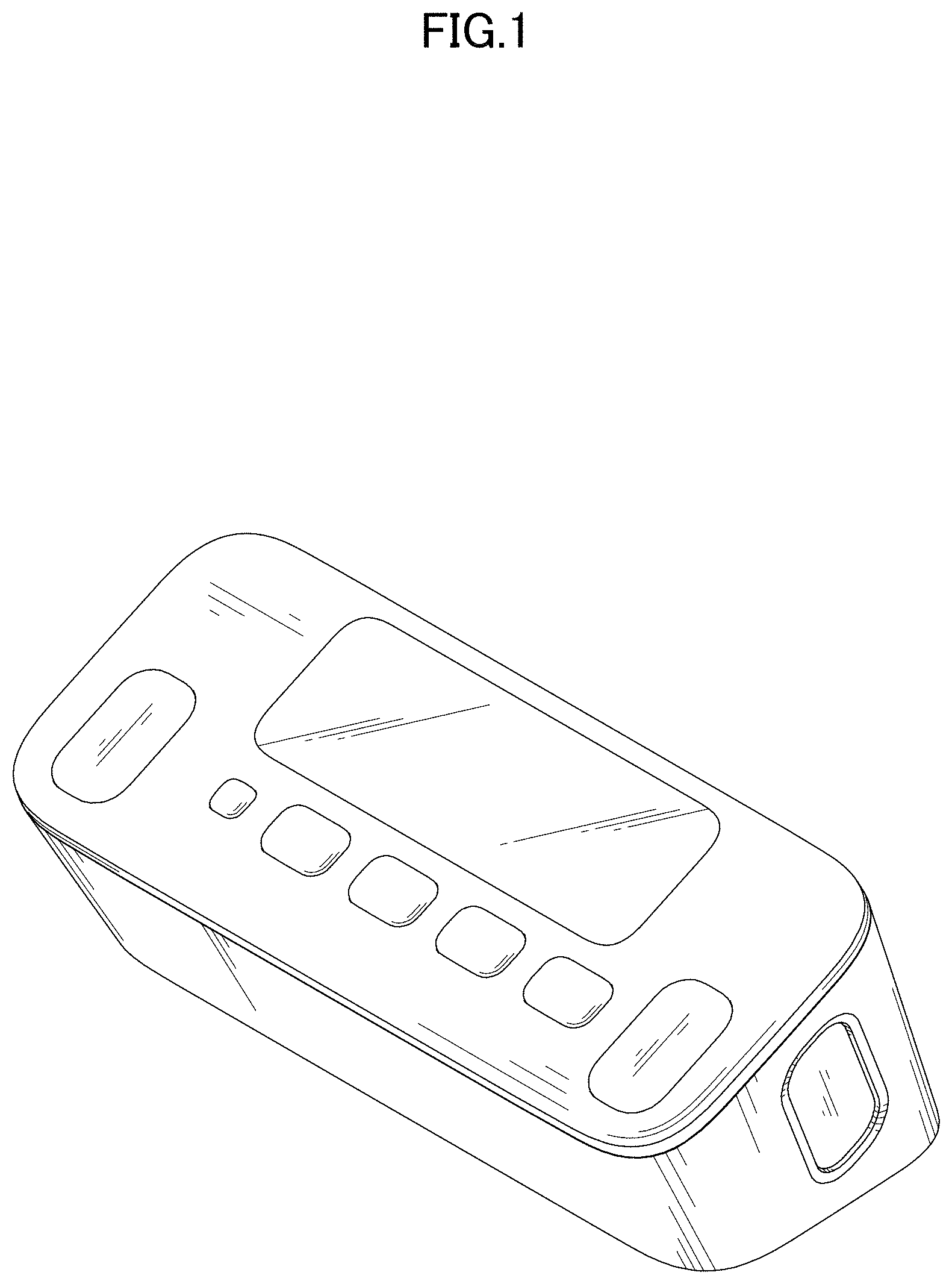
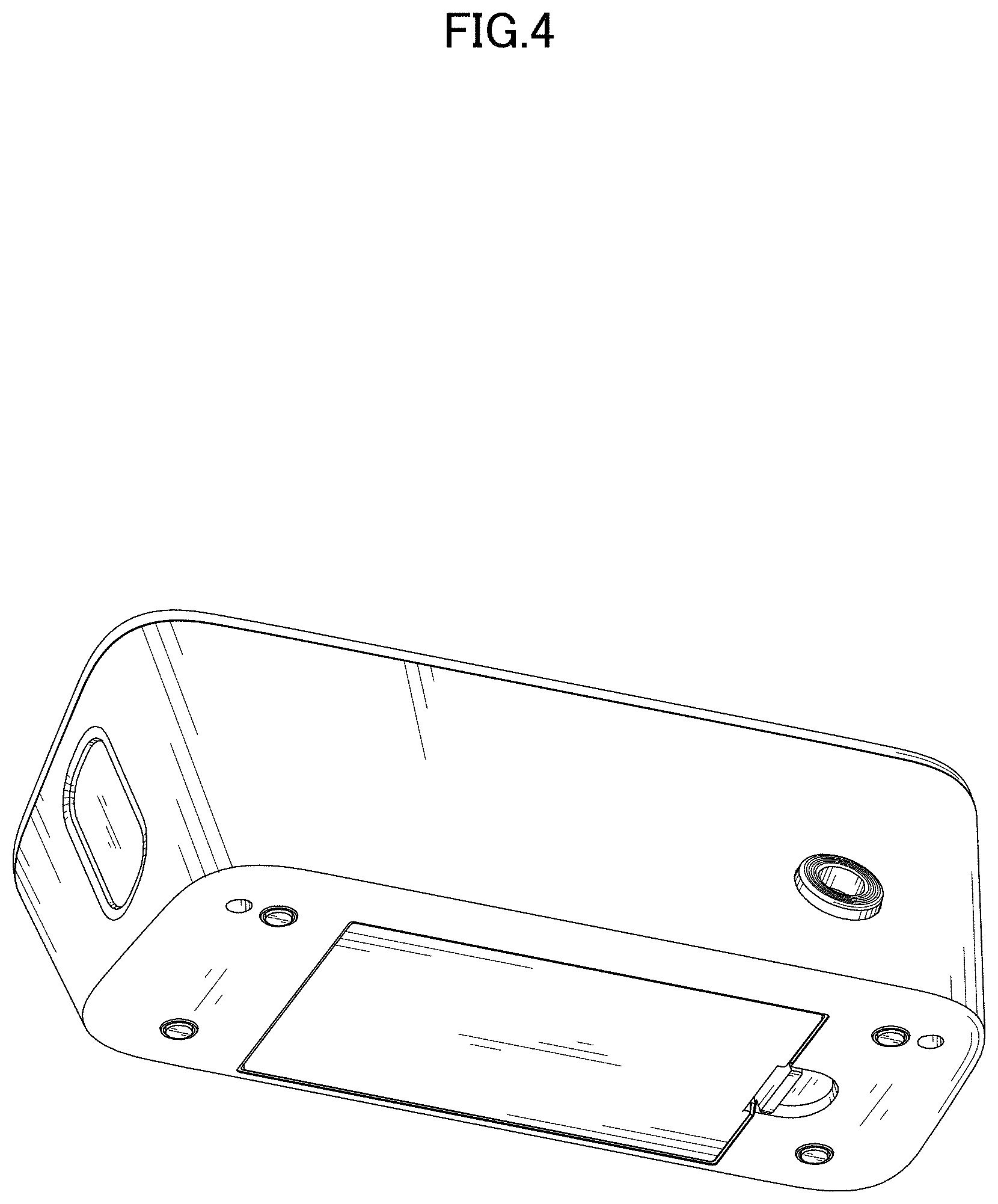
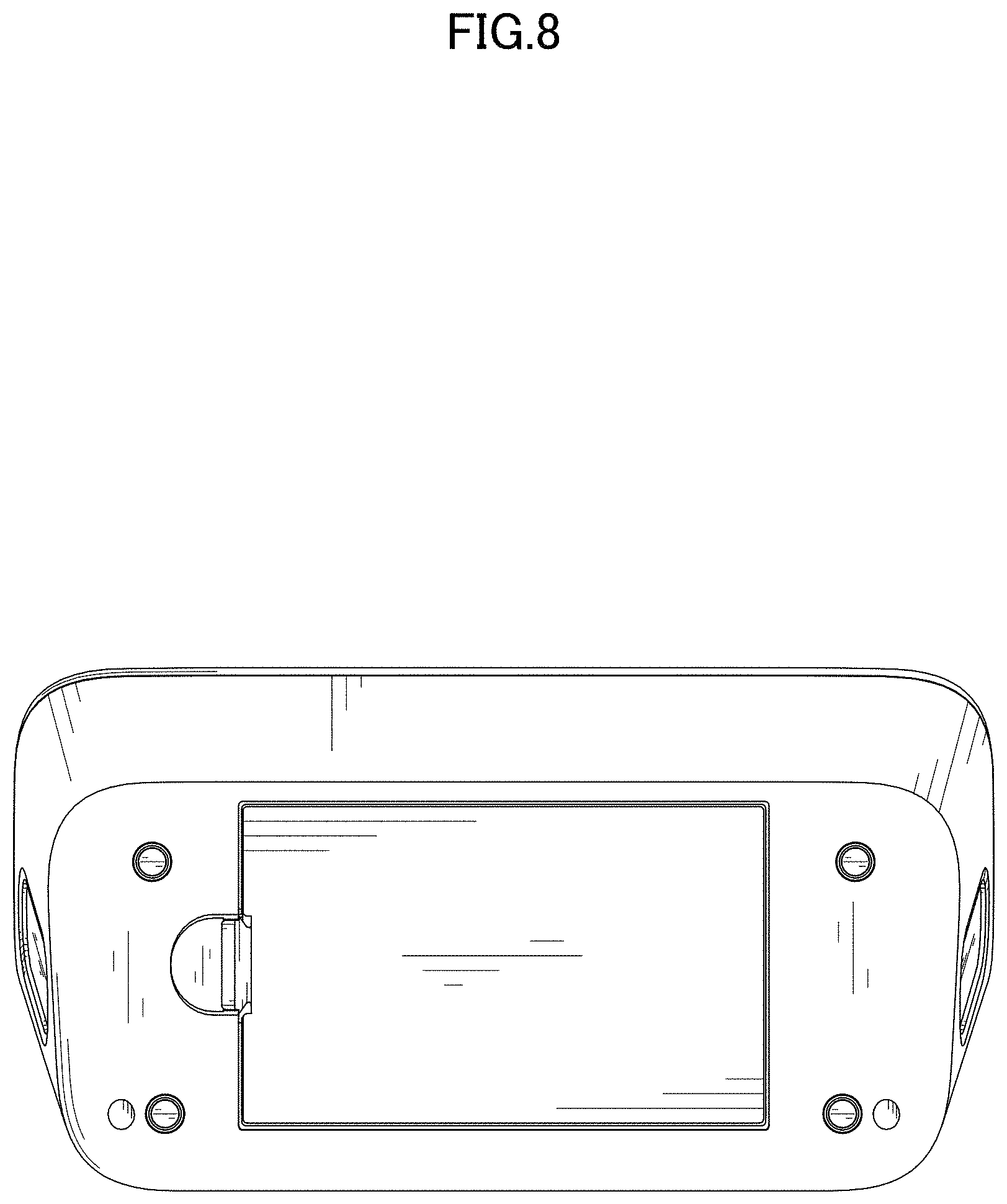
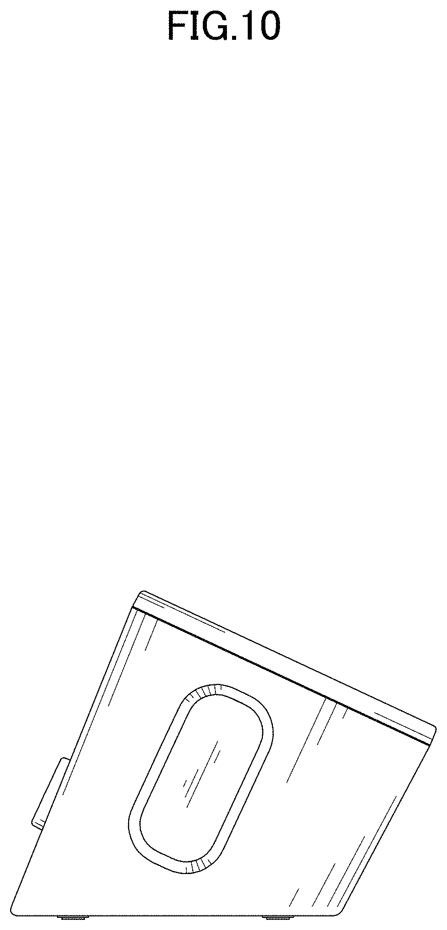
CLAIM The ornamental design for a sphygmomanometer with electrocardiograph, as shown.
| Inventors: | Hirasawa; Asa (Muko, JP), Ogihara; Tsuyoshi (Muko, JP), Nishiyama; Kengo (Muko, JP), Inoue; Kosuke (Muko, JP) | ||||||||||
|---|---|---|---|---|---|---|---|---|---|---|---|
| Applicant: |
|
||||||||||
| Assignee: | OMRON HEALTHCARE Co., Ltd.
(Kyoto, JP) |
||||||||||
| Appl. No.: | D/654,417 | ||||||||||
| Filed: | June 24, 2018 |
Foreign Application Priority Data
| Dec 26, 2017 [JP] | 2017-029152 | |||
| Current U.S. Class: | D24/165 |
| Current International Class: | 2402 |
| Field of Search: | ;D24/107,164,165-168,186,187 ;D10/75,70,98 |
References Cited [Referenced By]
U.S. Patent Documents
| D533666 | December 2006 | Kobayashi |
| D571013 | June 2008 | Kitamura |
| D583060 | December 2008 | Kitamura |
| D583474 | December 2008 | Mitsunami |
| D609344 | February 2010 | Hara |
| D651319 | December 2011 | Hara |
| D663843 | July 2012 | Wang |
| D809662 | February 2018 | Shi |
| D814039 | March 2018 | Shinozaki |
Attorney, Agent or Firm: Capitol City TechLaw
Description
FIG. 1 is a front, top, and right side perspective view of a sphygmomanometer with electrocardiograph showing our new design;
FIG. 2 is a rear, top, and left side perspective view thereof;
FIG. 3 is a front, bottom, and right side perspective view thereof;
FIG. 4 is a rear, bottom, and right side perspective view thereof;
FIG. 5 is a front view thereof;
FIG. 6 is a rear view thereof;
FIG. 7 is a top view thereof;
FIG. 8 is a bottom view thereof;
FIG. 9 is a right side view thereof; and,
FIG. 10 is a left side view thereof.
* * * * *
D00000
D00001
D00002
D00003
D00004
D00005
D00006
D00007
D00008
D00009
D00010
XML
uspto.report is an independent third-party trademark research tool that is not affiliated, endorsed, or sponsored by the United States Patent and Trademark Office (USPTO) or any other governmental organization. The information provided by uspto.report is based on publicly available data at the time of writing and is intended for informational purposes only.
While we strive to provide accurate and up-to-date information, we do not guarantee the accuracy, completeness, reliability, or suitability of the information displayed on this site. The use of this site is at your own risk. Any reliance you place on such information is therefore strictly at your own risk.
All official trademark data, including owner information, should be verified by visiting the official USPTO website at www.uspto.gov. This site is not intended to replace professional legal advice and should not be used as a substitute for consulting with a legal professional who is knowledgeable about trademark law.