Flow ingestion discourager with ridged pattern for a turbomachine shroud
Delvaux , et al. Dec
U.S. patent number D871,468 [Application Number D/598,691] was granted by the patent office on 2019-12-31 for flow ingestion discourager with ridged pattern for a turbomachine shroud. This patent grant is currently assigned to General Electric Company. The grantee listed for this patent is General Electric Company. Invention is credited to John McConnell Delvaux, Matthew Troy Hafner, Glenn Curtis Taxacher.


| United States Patent | D871,468 |
| Delvaux , et al. | December 31, 2019 |
Flow ingestion discourager with ridged pattern for a turbomachine shroud
Claims
CLAIM The ornamental design for a flow ingestion discourager with ridged pattern for a turbomachine shroud, as shown and described.
| Inventors: | Delvaux; John McConnell (Fountain Inn, SC), Hafner; Matthew Troy (Honea Path, SC), Taxacher; Glenn Curtis (Simpsonville, SC) | ||||||||||
|---|---|---|---|---|---|---|---|---|---|---|---|
| Applicant: |
|
||||||||||
| Assignee: | General Electric Company
(Schenectady, NY) |
||||||||||
| Appl. No.: | D/598,691 | ||||||||||
| Filed: | March 28, 2017 |
| Current U.S. Class: | D15/138 |
| Current International Class: | 1509 |
| Field of Search: | ;D15/7,122,123,126,138,139,199 |
References Cited [Referenced By]
U.S. Patent Documents
| 2812159 | November 1957 | Krebs |
| 5618161 | April 1997 | Papageorgiou |
| 5632598 | May 1997 | Maier |
| D586831 | February 2009 | Khanin |
| D611510 | March 2010 | Khanin |
| 2002/0164247 | November 2002 | Nadeau |
| 2007/0231131 | October 2007 | Aynes |
| 2008/0072572 | March 2008 | Beutin |
| 2008/0298970 | December 2008 | Ferber |
| 2012/0121437 | May 2012 | Borufka |
| 2012/0141253 | June 2012 | Weidmann |
| 2012/0230818 | September 2012 | Shepherd |
| 2013/0183135 | July 2013 | Fishler |
| 2013/0243600 | September 2013 | Noble |
| 2015/0017013 | January 2015 | Tozzi |
| 2016/0024939 | January 2016 | Nilsson |
| 2016/0025108 | January 2016 | Englebert |
| 2016/0221881 | August 2016 | Delvaux |
| 2016/0245103 | August 2016 | Gimat |
| 2016/0273373 | September 2016 | Filipenco |
| 2018/0371922 | December 2018 | Sitkiewicz |
Attorney, Agent or Firm: Wilson; Charlotte C. Pemrick; James W.
Description
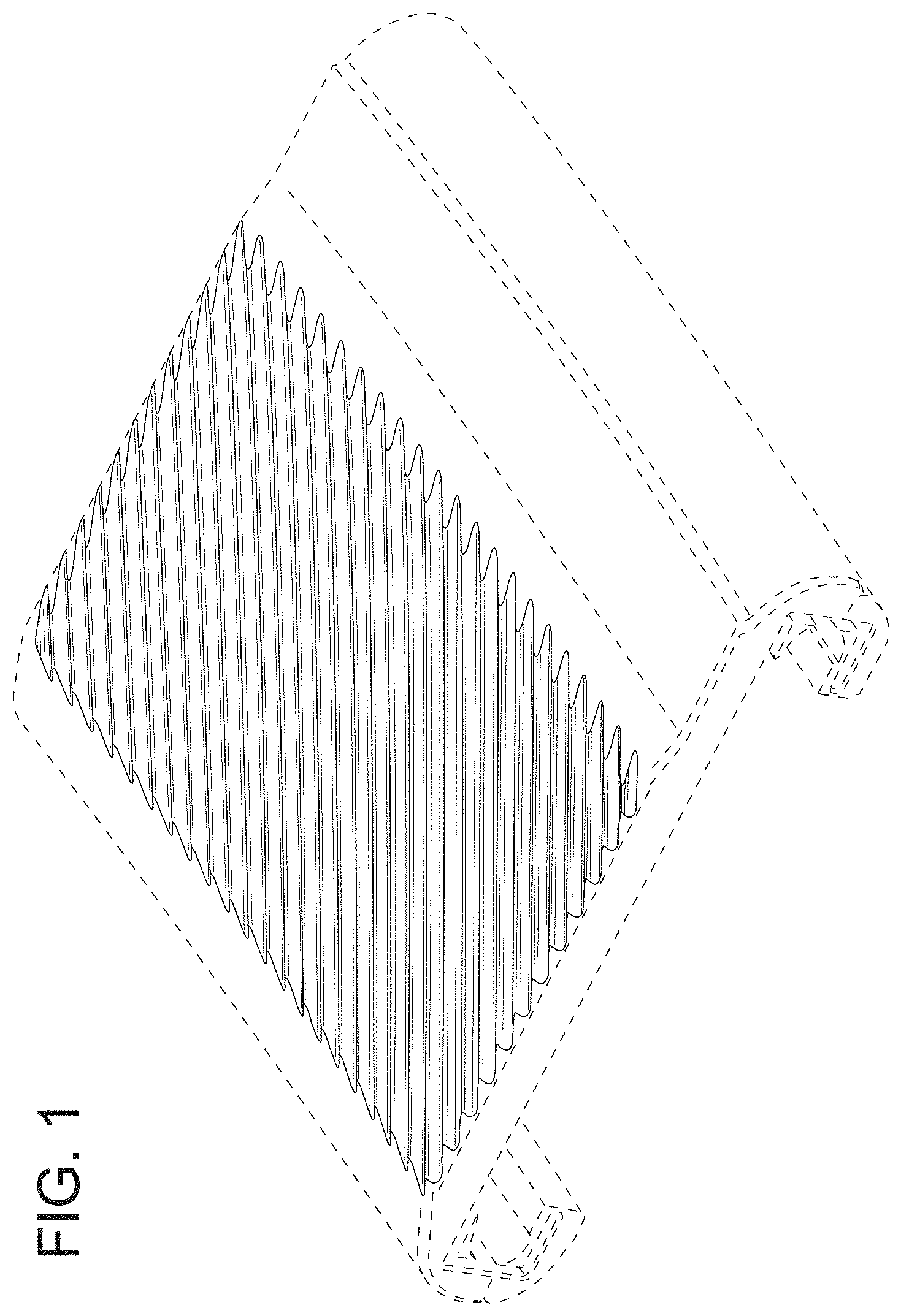
FIG. 1 is a top and perspective view of a design for a flow ingestion discourager with a ridged pattern for a turbomachine shroud.
FIG. 2 is a top view of the design for the flow ingestion discourager with a ridged pattern of FIG. 1 for a turbomachine shroud.
FIG. 3 is a side, elevational view of the design for the flow ingestion discourager of FIG. 1 for a turbomachine shroud, illustrating the ridged pattern being located towards the forward end of the shroud. The forward end is the left side of the shroud in FIG. 3.
FIG. 4 is a side, elevational view of the design for the flow ingestion discourager of FIG. 1 for a turbomachine shroud, illustrating the ridged pattern being located towards the forward end of the shroud. The forward end is the right side of the shroud in FIG. 4.
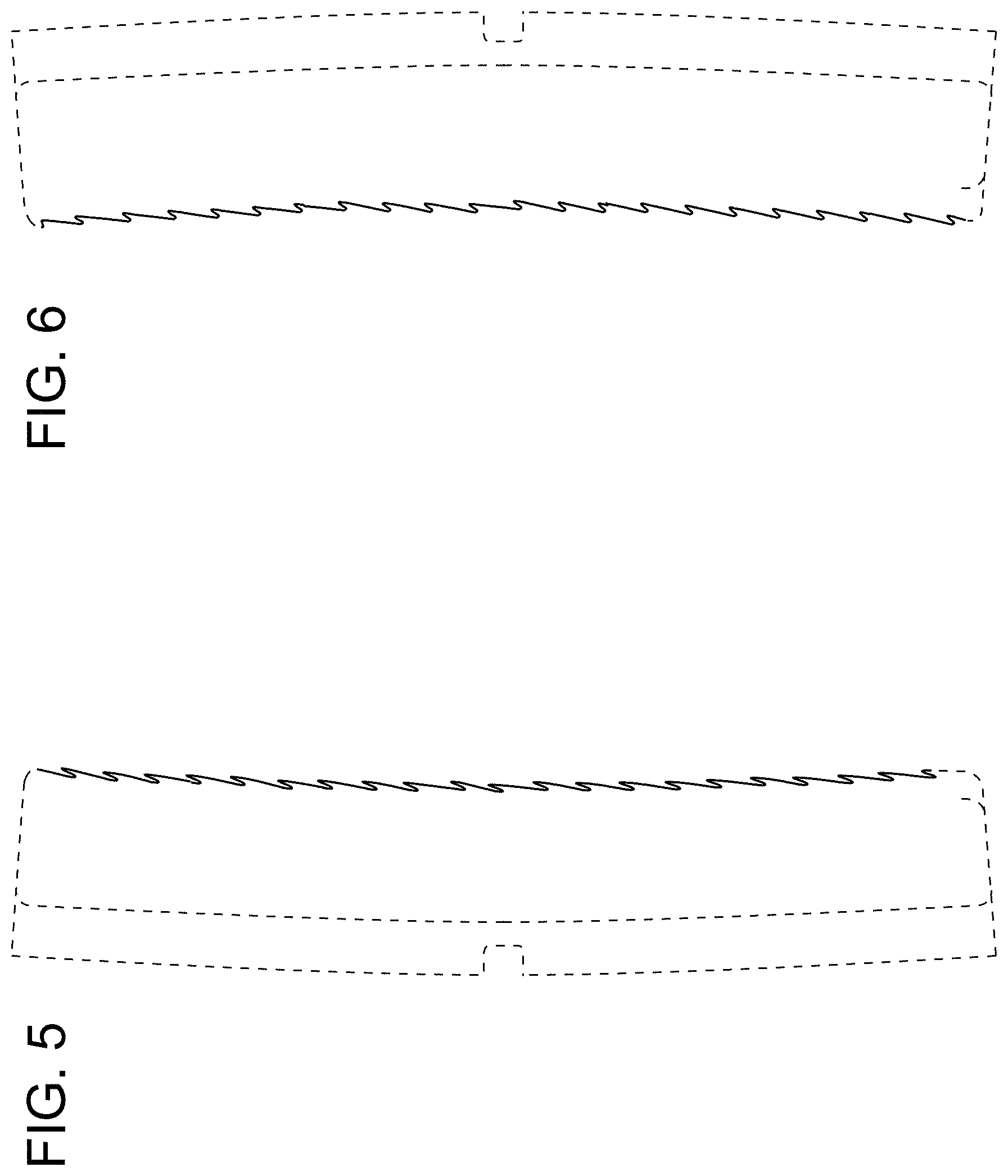
FIG. 5 is a front view of the design for the flow ingestion discourager with ridged pattern of FIG. 1 for a turbomachine shroud, illustrating a front edge of the ridged pattern on the shroud.
FIG. 6 is a rear view of the design for the flow ingestion discourager with ridged pattern of FIG. 1 for a turbomachine shroud, illustrating a rear or aft edge of the ridged pattern on the shroud.
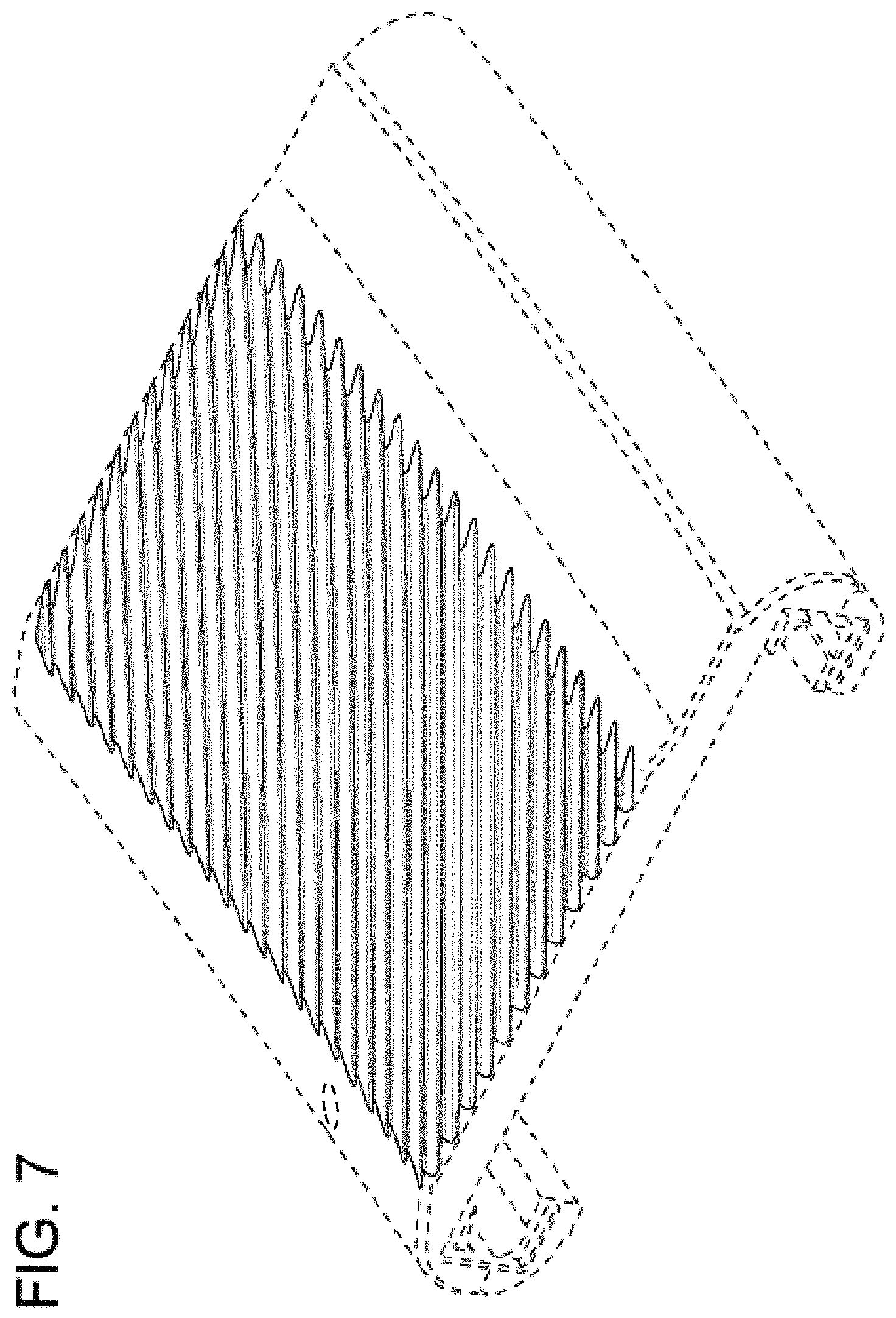
FIG. 7 is a top and perspective view of the design for the flow ingestion discourager with a ridged pattern of FIG. 1 for a turbomachine shroud, showing the position of the flow ingestion discourager relative to an inspection hole located in the forward end of the shroud.
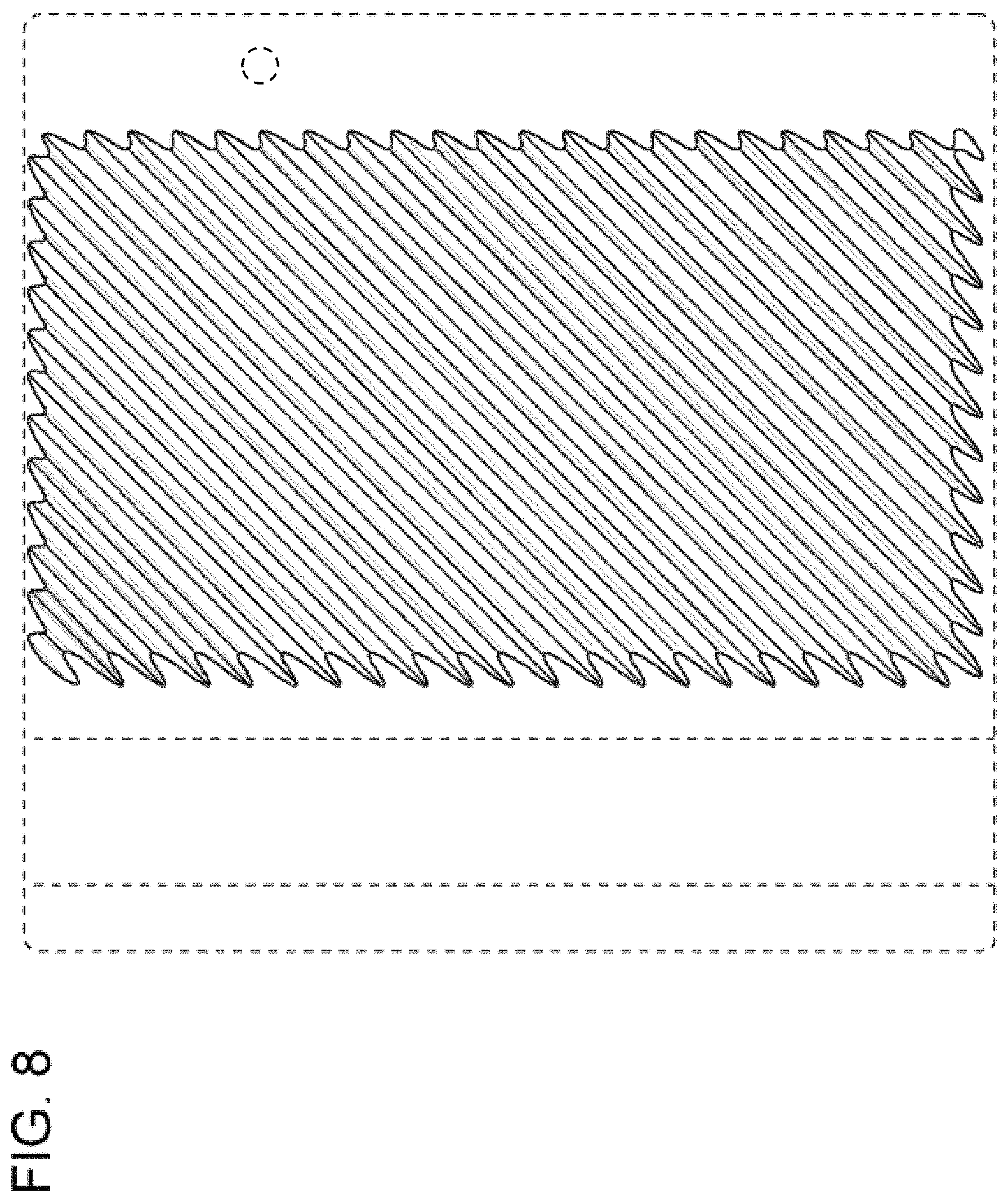
FIG. 8 is a top view of the design for the flow ingestion discourager with a ridged pattern of FIG. 1 for a turbomachine shroud, showing the position of the flow ingestion discourager relative to an inspection hole located in the forward end of the shroud; and,
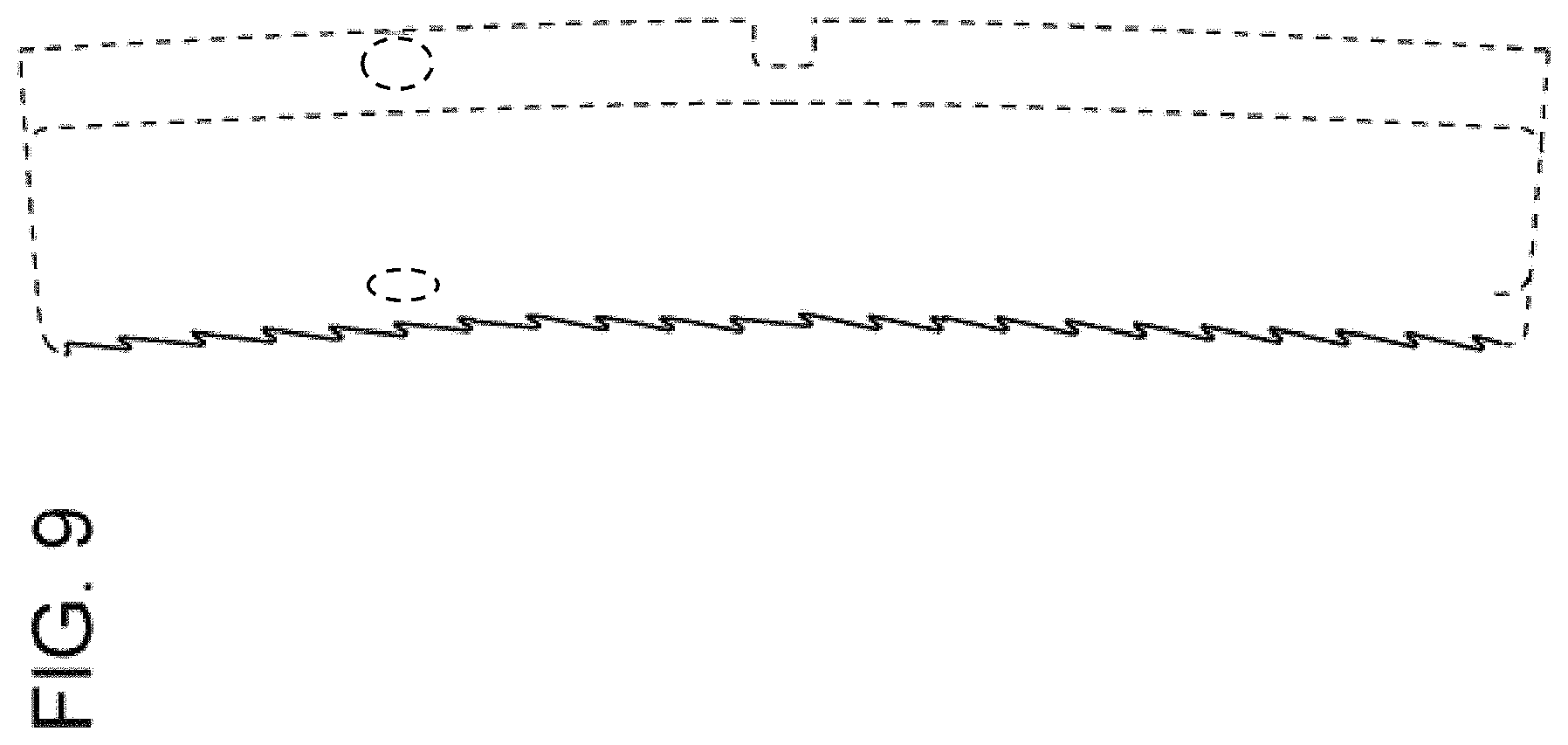
FIG. 9 is a front view of the design for a flow ingestion discourager with a ridged pattern of FIG. 1 for a turbomachine shroud, showing the position of the flow ingestion discourager relative to an inspection hole located in the forward end of the shroud.
The broken lines in the drawings represent portions of the flow ingestion discourager with ridged pattern for a turbomachine shroud which form no part of the claimed design.
* * * * *
D00000
D00001
D00002
D00003
D00004
D00005
D00006
D00007
XML
uspto.report is an independent third-party trademark research tool that is not affiliated, endorsed, or sponsored by the United States Patent and Trademark Office (USPTO) or any other governmental organization. The information provided by uspto.report is based on publicly available data at the time of writing and is intended for informational purposes only.
While we strive to provide accurate and up-to-date information, we do not guarantee the accuracy, completeness, reliability, or suitability of the information displayed on this site. The use of this site is at your own risk. Any reliance you place on such information is therefore strictly at your own risk.
All official trademark data, including owner information, should be verified by visiting the official USPTO website at www.uspto.gov. This site is not intended to replace professional legal advice and should not be used as a substitute for consulting with a legal professional who is knowledgeable about trademark law.