Electrical receptacle
Byrne , et al. Dec
U.S. patent number D870,672 [Application Number D/607,354] was granted by the patent office on 2019-12-24 for electrical receptacle. The grantee listed for this patent is Norman R. Byrne, Joshua M. McBryde, Randell E. Pate, Shane Rogers, Joseph D. Ward. Invention is credited to Norman R. Byrne, Joshua M. McBryde, Randell E. Pate, Shane Rogers, Joseph D. Ward.


| United States Patent | D870,672 |
| Byrne , et al. | December 24, 2019 |
Electrical receptacle
Claims
CLAIM The ornamental design for an electrical receptacle, as shown and described.
| Inventors: | Byrne; Norman R. (Ada, MI), Rogers; Shane (Rockford, MI), Ward; Joseph D. (Grand Rapids, MI), McBryde; Joshua M. (Grand Rapids, MI), Pate; Randell E. (Jenison, MI) | ||||||||||
|---|---|---|---|---|---|---|---|---|---|---|---|
| Applicant: |
|
||||||||||
| Appl. No.: | D/607,354 | ||||||||||
| Filed: | June 12, 2017 |
| Current U.S. Class: | D13/139.7 |
| Current International Class: | 1303 |
| Field of Search: | ;D13/139.7,139.1,139.2,139.3,139.4,139.5,139.6,139.8 ;D14/110 |
References Cited [Referenced By]
U.S. Patent Documents
| D375292 | November 1996 | D'Amato |
| 5595503 | January 1997 | Pittman et al. |
| 5775921 | July 1998 | Chou |
| 5997310 | December 1999 | Chiu et al. |
| 6089921 | July 2000 | Chou |
| 6595782 | July 2003 | Hsiao |
| 6793499 | September 2004 | Chen |
| 6821134 | November 2004 | Chen |
| 7255568 | August 2007 | Wu |
| 7533223 | July 2009 | Wadsworth |
| 7575436 | August 2009 | Devlin et al. |
| D614574 | April 2010 | Thommes |
| 7845951 | December 2010 | Goon |
| 7850458 | December 2010 | Wadsworth |
| 7892036 | February 2011 | Lee |
| D633870 | March 2011 | Thommes |
| 7914292 | March 2011 | Honda |
| 7946852 | May 2011 | John |
| D640199 | June 2011 | Wilson |
| 8123528 | February 2012 | Devlin et al. |
| 8167622 | May 2012 | Zhou |
| 8469730 | June 2013 | Garb et al. |
| 8500492 | August 2013 | Brown et al. |
| 8747119 | June 2014 | Hsu |
| D714726 | October 2014 | Byrne et al. |
| D721330 | January 2015 | Byrne et al. |
| D722563 | February 2015 | Byrne et al. |
| D730834 | June 2015 | Byrne |
| D739821 | September 2015 | Byrne et al. |
| D741266 | October 2015 | Byrne |
| D741267 | October 2015 | Byrne |
| D759596 | June 2016 | Byrne et al. |
| D762175 | July 2016 | Byrne et al. |
| D803160 | November 2017 | Ho'o |
| D807829 | January 2018 | Byrne et al. |
| D817888 | May 2018 | Yu |
| D826162 | August 2018 | Byrne |
| 2013/0115804 | May 2013 | Vallon |
Other References
|
Co-pending and commonly-owned design U.S. Appl. No. 29/607,299, filed Jun. 12, 2017. cited by applicant. |
Primary Examiner: Eland; Bridget L
Attorney, Agent or Firm: Gardner, Linn, Burkhart & Ondersma LLP
Description
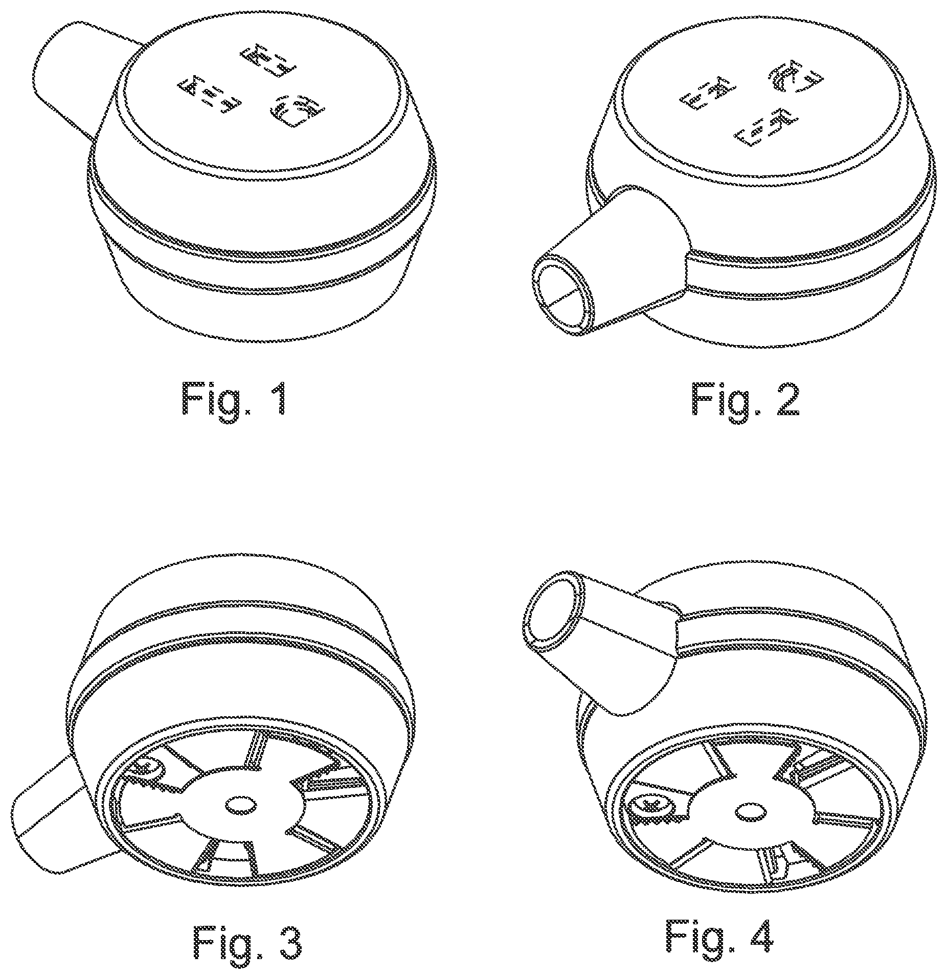
FIG. 1 is a front, bottom, left side perspective view of an electrical receptacle showing our new design;
FIG. 2 is a front, top, left side perspective view thereof;
FIG. 3 is a rear, bottom, left side perspective view thereof;
FIG. 4 is a rear, top, left side perspective view thereof;
FIG. 5 is a bottom plan view thereof;
FIG. 6 is a top plan view thereof;
FIG. 7 is a front elevation thereof;
FIG. 8 is a rear elevation thereof;
FIG. 9 is a right side elevation thereof; and,
FIG. 10 is a left side elevation thereof.
The broken lines immediately adjacent the claim represent the bounds of the claimed design while all other broken lines are directed to environment and are for illustrative purposes only; the broken lines form no part of the claimed design.
* * * * *
D00000
D00001
D00002
XML
uspto.report is an independent third-party trademark research tool that is not affiliated, endorsed, or sponsored by the United States Patent and Trademark Office (USPTO) or any other governmental organization. The information provided by uspto.report is based on publicly available data at the time of writing and is intended for informational purposes only.
While we strive to provide accurate and up-to-date information, we do not guarantee the accuracy, completeness, reliability, or suitability of the information displayed on this site. The use of this site is at your own risk. Any reliance you place on such information is therefore strictly at your own risk.
All official trademark data, including owner information, should be verified by visiting the official USPTO website at www.uspto.gov. This site is not intended to replace professional legal advice and should not be used as a substitute for consulting with a legal professional who is knowledgeable about trademark law.