Pallet
Lin , et al. Dec
U.S. patent number D869,812 [Application Number D/624,806] was granted by the patent office on 2019-12-10 for pallet. This patent grant is currently assigned to Inteplast Group Corporation. The grantee listed for this patent is Inteplast Group Corporation. Invention is credited to Yaw-kuen Lin, Douglas R. Lude.


| United States Patent | D869,812 |
| Lin , et al. | December 10, 2019 |
Pallet
Claims
CLAIM The ornamental design for a pallet, as shown and described.
| Inventors: | Lin; Yaw-kuen (Parsippany, NJ), Lude; Douglas R. (Auburn, IN) | ||||||||||
|---|---|---|---|---|---|---|---|---|---|---|---|
| Applicant: |
|
||||||||||
| Assignee: | Inteplast Group Corporation
(Livingston, NJ) |
||||||||||
| Appl. No.: | D/624,806 | ||||||||||
| Filed: | November 3, 2017 |
| Current U.S. Class: | D34/38 |
| Current International Class: | 0908 |
| Field of Search: | ;D34/38 |
References Cited [Referenced By]
U.S. Patent Documents
| D279418 | June 1985 | Helmer |
| D279617 | July 1985 | Helmer |
| D288977 | March 1987 | Wind |
| D296599 | July 1988 | Bean |
| D357108 | April 1995 | Hutchison |
| 5433156 | July 1995 | Hutchison |
| 5794544 | August 1998 | Shuert |
| D403830 | January 1999 | Apps et al. |
| D404180 | January 1999 | Apps |
| 5887529 | March 1999 | John et al. |
| D410786 | June 1999 | Favaron |
| D443969 | June 2001 | Apps |
| 6250234 | June 2001 | Apps |
| D464186 | October 2002 | Medoff |
| D485659 | January 2004 | Medoff |
| 6807910 | October 2004 | Apps |
| D650546 | December 2011 | MacDonald et al. |
| D674984 | January 2013 | Reyhan |
| D708811 | July 2014 | Kelly et al. |
| D724809 | March 2015 | Howland et al. |
| D762939 | August 2016 | Johnson |
| D781023 | March 2017 | Johnson |
| D799781 | October 2017 | Blosser |
| D816287 | April 2018 | Hunt, III |
| D816288 | April 2018 | Hunt, III |
| D816939 | May 2018 | Blosser et al. |
| D822308 | July 2018 | Hunt, III |
| D822309 | July 2018 | Hunt, III |
| D838429 | January 2019 | Herbeck |
| 2007/0163473 | July 2007 | Shuert |
| 2008/0143514 | June 2008 | Valentinsson |
| 2008/0236455 | October 2008 | Naidu |
| 2009/0050029 | February 2009 | Ogburn |
| 2010/0288169 | November 2010 | Du Toit |
| 2014/0158025 | June 2014 | Apps |
| 2016/0368659 | December 2016 | Bastian, II |
| 2018/0370681 | December 2018 | Lin |
Other References
|
US. Pat. No. D. 799,781, as originally filed on Mar. 31, 2016, pp. 1-20. cited by applicant. |
Primary Examiner: Ramirez; Cynthia
Attorney, Agent or Firm: Lerner, David, Littenberg, Krumholz & Mentlik, LLP
Description
FIG. 1 is a front perspective view of a pallet according to our design;
FIG. 2 is a cross-sectional perspective view thereof taken along line 2-2 of FIG. 4;
FIG. 3 is a right side elevational view thereof, the left side elevational view being identical thereto;
FIG. 4 is a front elevational view thereof, the rear elevational view being identical thereto;
FIG. 5 is a top plan view thereof;
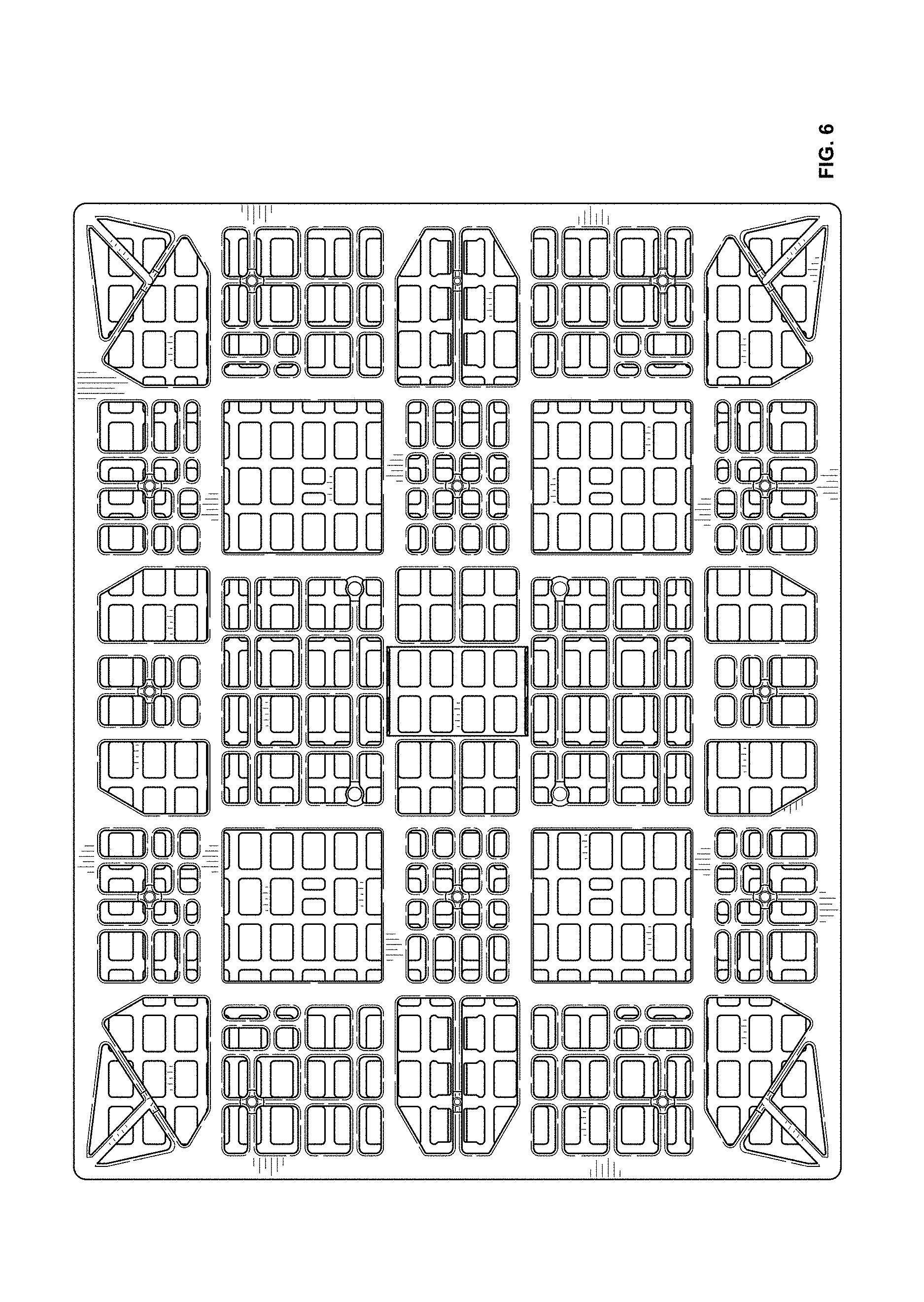
FIG. 6 is a bottom plan view thereof;
FIG. 7 is a cross-sectional view taken along line 7-7 of FIG. 1;
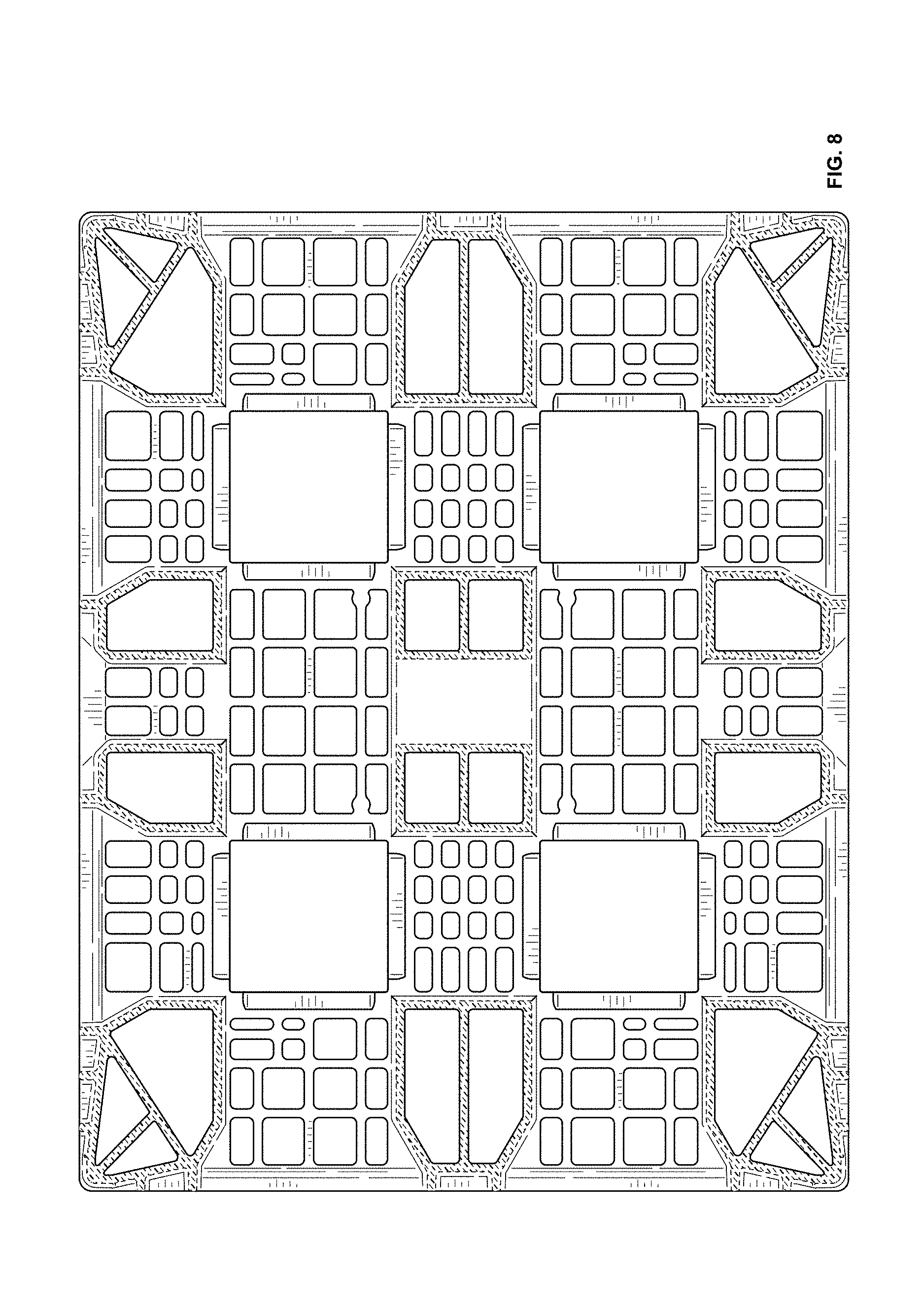
FIG. 8 is a cross-sectional view taken along line 8-8 of FIG. 3;
FIG. 9 is a cross-sectional view taken along line 9-9 of FIG. 3; and,
FIG. 10 is a bottom perspective view thereof.
The evenly-spaced broken lines shown in the drawings are for the purpose of illustrating environmental structure and form no part of the claimed design. The dash-dot lines are included to show boundaries that form no part of the claimed design.
* * * * *
D00000
D00001
D00002
D00003
D00004
D00005
D00006
D00007
D00008
D00009
XML
uspto.report is an independent third-party trademark research tool that is not affiliated, endorsed, or sponsored by the United States Patent and Trademark Office (USPTO) or any other governmental organization. The information provided by uspto.report is based on publicly available data at the time of writing and is intended for informational purposes only.
While we strive to provide accurate and up-to-date information, we do not guarantee the accuracy, completeness, reliability, or suitability of the information displayed on this site. The use of this site is at your own risk. Any reliance you place on such information is therefore strictly at your own risk.
All official trademark data, including owner information, should be verified by visiting the official USPTO website at www.uspto.gov. This site is not intended to replace professional legal advice and should not be used as a substitute for consulting with a legal professional who is knowledgeable about trademark law.