Projector lamp for vehicles
Kasuga , et al. Dec
U.S. patent number D869,697 [Application Number D/609,782] was granted by the patent office on 2019-12-10 for projector lamp for vehicles. This patent grant is currently assigned to Mitsubishi Electric Corporation. The grantee listed for this patent is Mitsubishi Electric Corporation. Invention is credited to Shinsaku Fukutaka, Akiko Imaishi, Kei Kasuga, Tsutomu Matsubara, Munetaka Nishihira, Reiko Sakata.


| United States Patent | D869,697 |
| Kasuga , et al. | December 10, 2019 |
Projector lamp for vehicles
Claims
CLAIM The ornamental design for a projector lamp for vehicles, as shown and described.
| Inventors: | Kasuga; Kei (Tokyo, JP), Matsubara; Tsutomu (Tokyo, JP), Nishihira; Munetaka (Tokyo, JP), Sakata; Reiko (Tokyo, JP), Fukutaka; Shinsaku (Tokyo, JP), Imaishi; Akiko (Tokyo, JP) | ||||||||||
|---|---|---|---|---|---|---|---|---|---|---|---|
| Applicant: |
|
||||||||||
| Assignee: | Mitsubishi Electric Corporation
(Tokyo, JP) |
||||||||||
| Appl. No.: | D/609,782 | ||||||||||
| Filed: | July 5, 2017 |
Foreign Application Priority Data
| Apr 4, 2017 [JP] | 2017-007117 | |||
| Current U.S. Class: | D26/28 |
| Current International Class: | 2606 |
| Field of Search: | ;D26/28-36,139 |
References Cited [Referenced By]
U.S. Patent Documents
| D708373 | July 2014 | Kani |
| D711023 | August 2014 | Wu |
| D747517 | January 2016 | Lai |
| D760407 | June 2016 | Yang |
Attorney, Agent or Firm: Studebaker & Brackett PC
Description
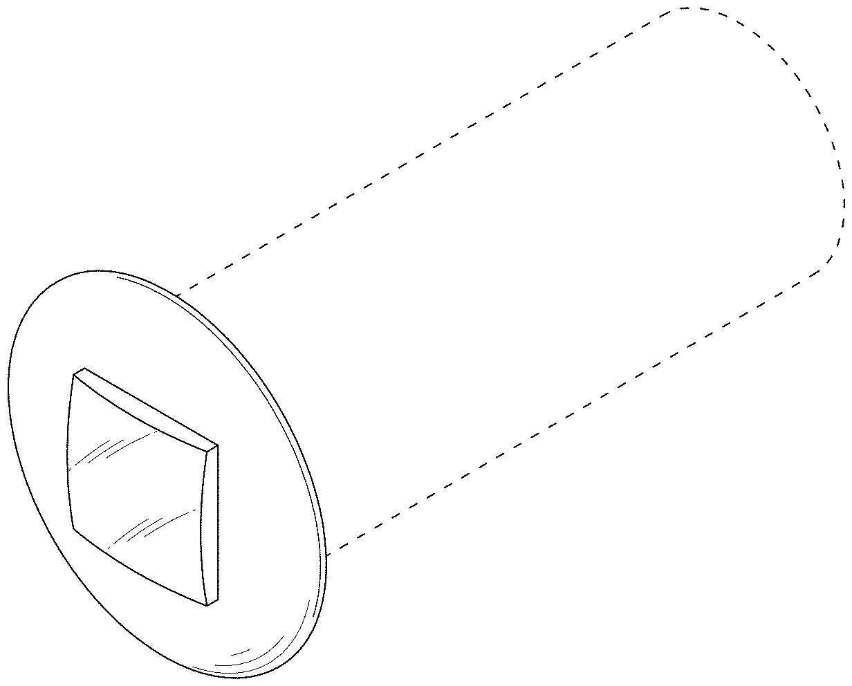
FIG. 1 is a perspective view of the front, right and top sides of a projector lamp for vehicles showing our new design;
FIG. 2 is a front view thereof;
FIG. 3 is a rear view thereof;
FIG. 4 is a right side view thereof;
FIG. 5 is a top side view thereof;
FIG. 6 is a cross-sectional view thereof; taken along line 6-6 of FIG. 2 with the internal system omitted; and,
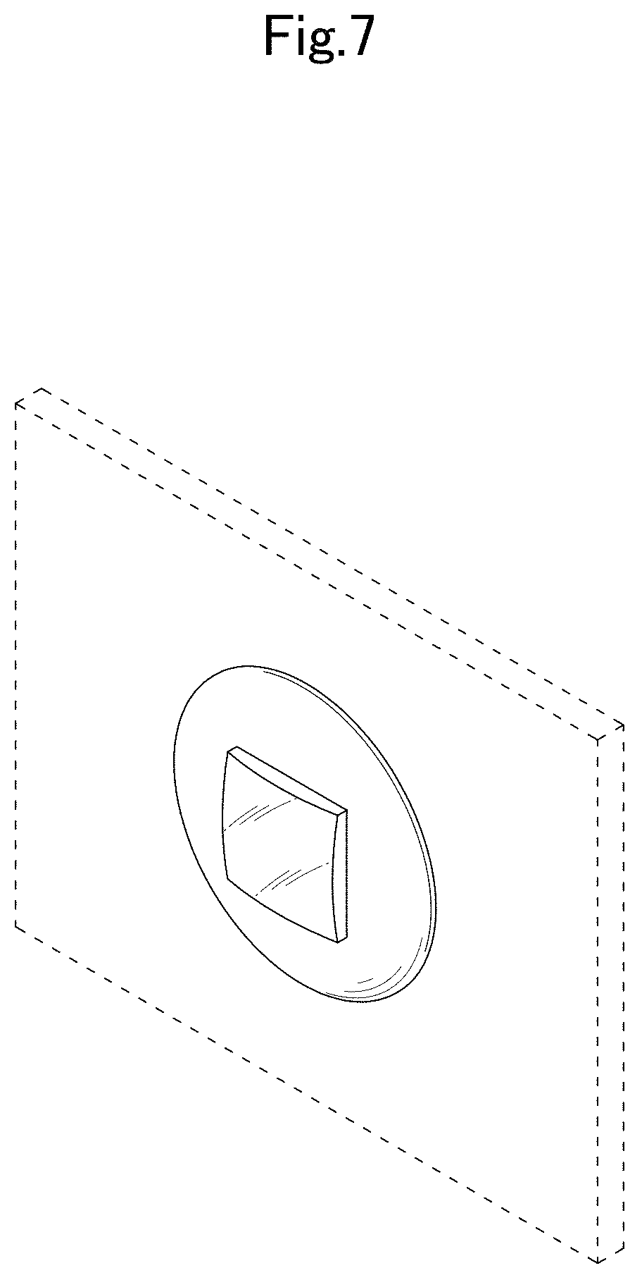
FIG. 7 is a reference view showing the use state thereof.
The parts shown in the broken lines do not form part of the claimed designs. The left views are omitted because they are mirror images of the right views.
* * * * *
D00000
D00001
D00002
D00003
D00004
D00005
D00006
D00007
XML
uspto.report is an independent third-party trademark research tool that is not affiliated, endorsed, or sponsored by the United States Patent and Trademark Office (USPTO) or any other governmental organization. The information provided by uspto.report is based on publicly available data at the time of writing and is intended for informational purposes only.
While we strive to provide accurate and up-to-date information, we do not guarantee the accuracy, completeness, reliability, or suitability of the information displayed on this site. The use of this site is at your own risk. Any reliance you place on such information is therefore strictly at your own risk.
All official trademark data, including owner information, should be verified by visiting the official USPTO website at www.uspto.gov. This site is not intended to replace professional legal advice and should not be used as a substitute for consulting with a legal professional who is knowledgeable about trademark law.