Pinpointer metal detector
Griffin Nov
U.S. patent number D867,168 [Application Number D/656,738] was granted by the patent office on 2019-11-19 for pinpointer metal detector. This patent grant is currently assigned to FIRST TEXAS PRODUCTS, L.P.. The grantee listed for this patent is FIRST TEXAS PRODUCTS, LLC. Invention is credited to John Griffin.


View All Diagrams
| United States Patent | D867,168 |
| Griffin | November 19, 2019 |
Pinpointer metal detector
Claims
CLAIM The ornamental design for a pinpointer metal detector, as shown and described.
| Inventors: | Griffin; John (Las Cruces, NM) | ||||||||||
|---|---|---|---|---|---|---|---|---|---|---|---|
| Applicant: |
|
||||||||||
| Assignee: | FIRST TEXAS PRODUCTS, L.P. (El
Paso, TX) |
||||||||||
| Appl. No.: | D/656,738 | ||||||||||
| Filed: | July 16, 2018 |
| Current U.S. Class: | D10/47 |
| Current International Class: | 1004 |
| Field of Search: | ;D10/47 |
References Cited [Referenced By]
U.S. Patent Documents
| D459244 | June 2002 | Rigby |
| D497559 | October 2004 | Johnson |
| D513706 | January 2006 | Johnson |
| D583261 | December 2008 | Johnson |
| D663634 | July 2012 | Townsend |
| D694130 | November 2013 | Manneschi |
| D719853 | December 2014 | Manneschi |
| D796971 | September 2017 | Dubos |
Attorney, Agent or Firm: Westerman, Hattori, Daniels & Adrian, LLP Parker; Stephen B.
Description
FIG. 1 is a front view of a pinpointer metal detector according to one embodiment of the present design;
FIG. 2 is a rear view of the pinpointer metal detector shown in FIG. 1;
FIG. 3 is a right side view of the pinpointer metal detector shown in FIG. 1 from the right side of FIG. 1;
FIG. 4 is a left side view of the pinpointer metal detector shown in FIG. 1 from the left side of FIG. 1;
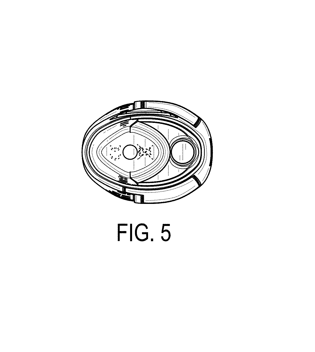
FIG. 5 is a bottom end view of the pinpointer metal detector shown in FIG. 1 from the bottom end of FIG. 1;
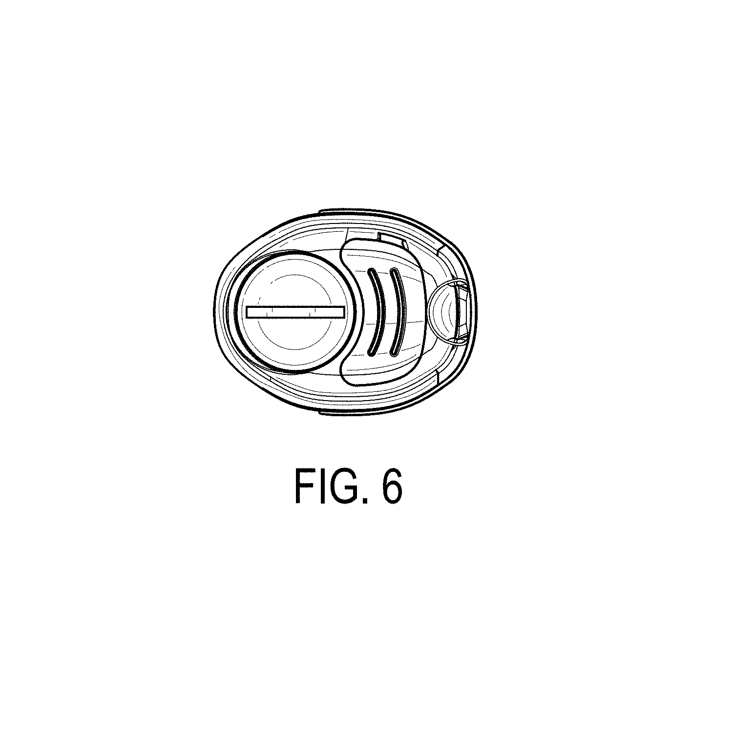
FIG. 6 is a top end view of the pinpointer metal detector shown in FIG. 1 from the top end of FIG. 1;
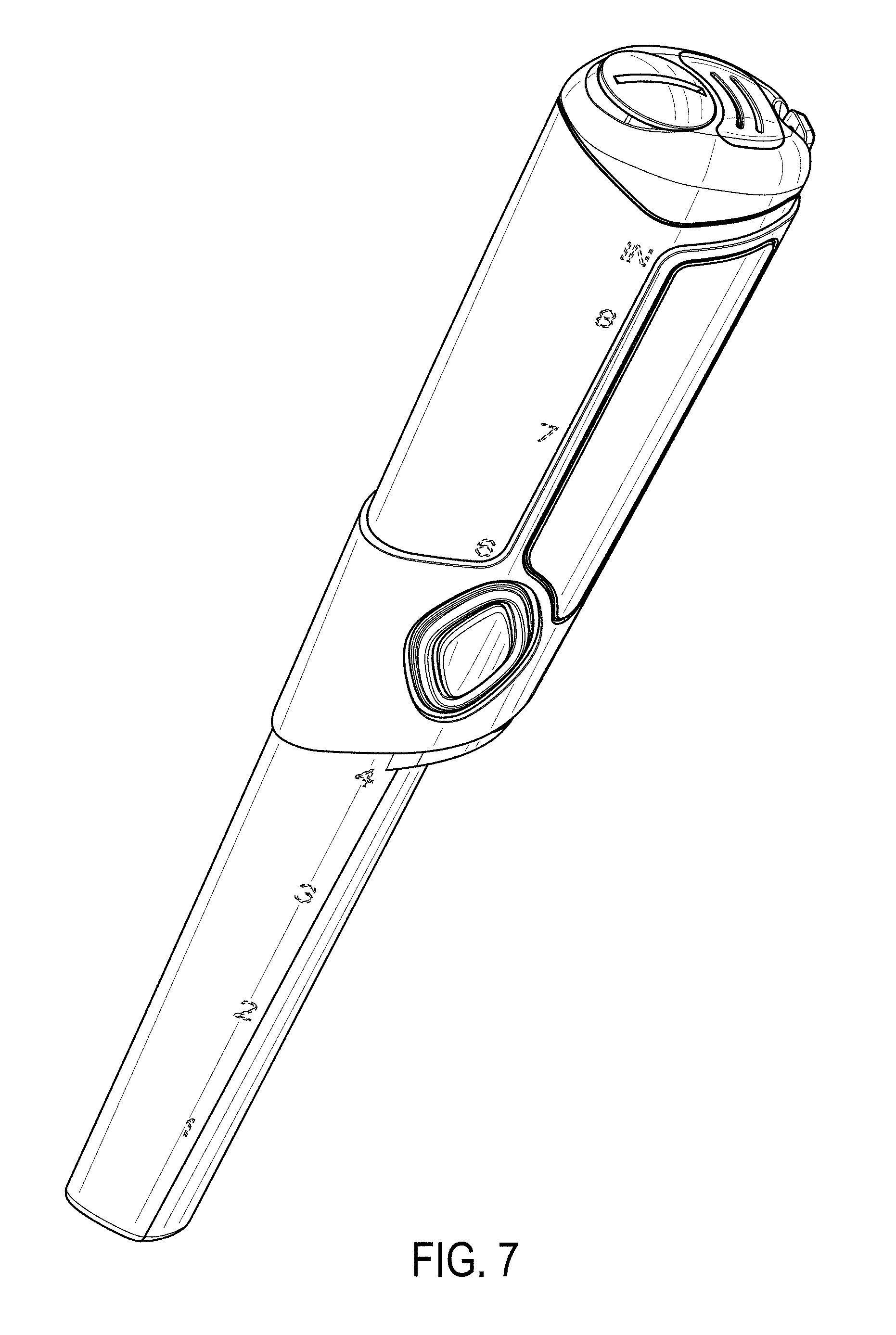
FIG. 7 is a front perspective view of the pinpointer metal detector shown in FIG. 1 from a top-left direction;
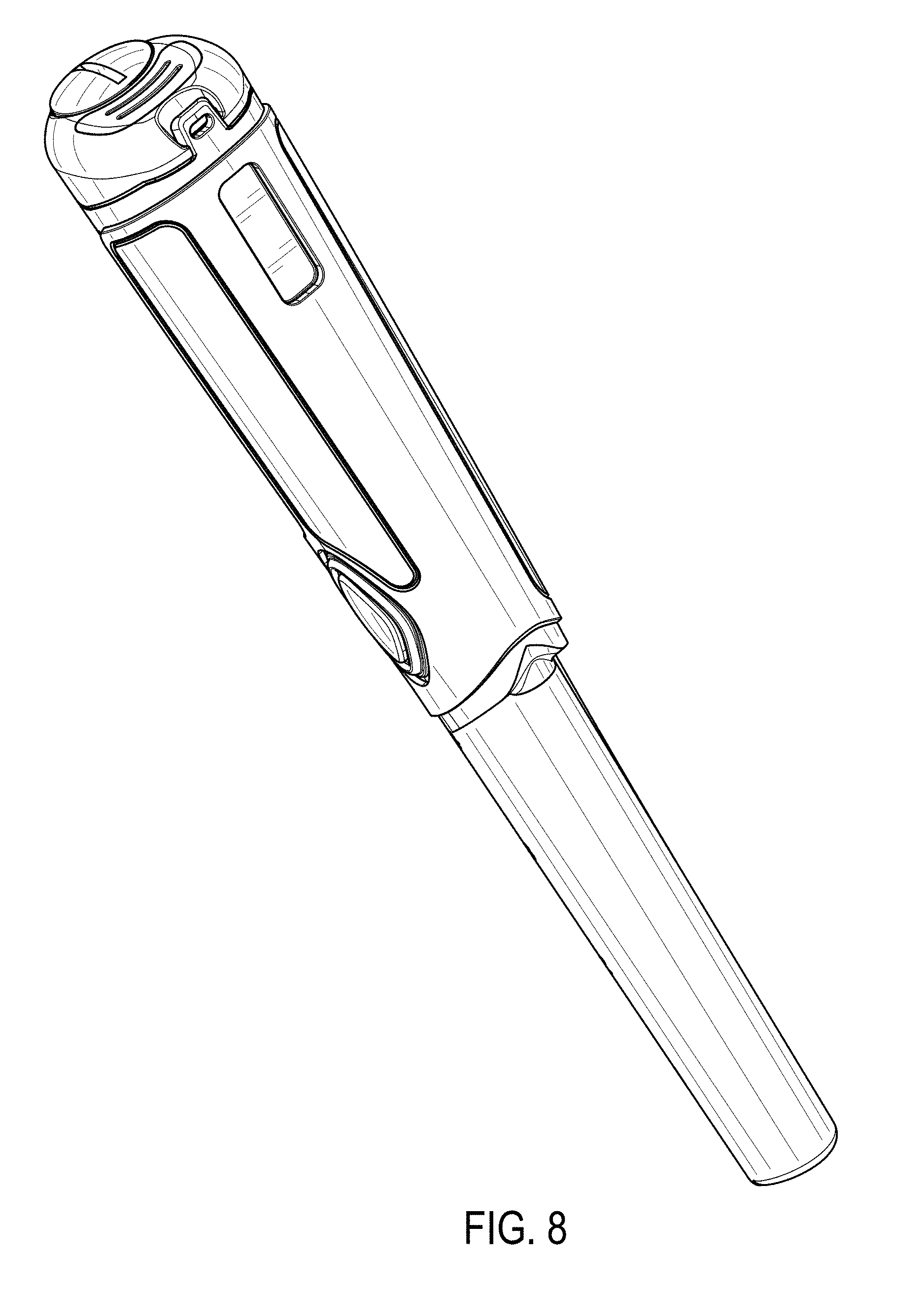
FIG. 8 is a right side perspective view of the pinpointer metal detector shown in FIG. 1 front a top-front direction;
FIG. 9 is a rear perspective view of the pinpointer metal detector shown in FIG. 1 from a rear-top direction;
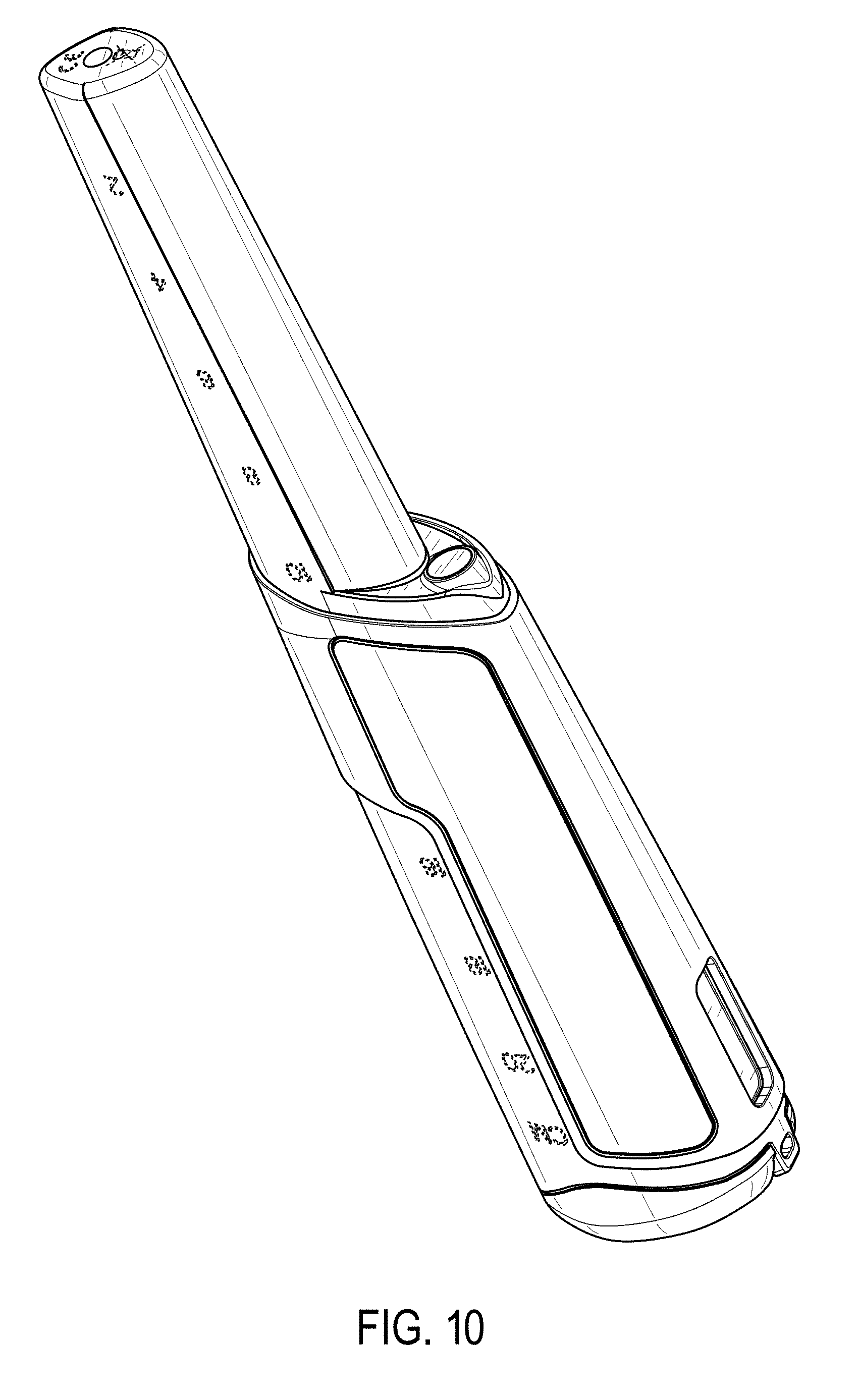
FIG. 10 is a right side perspective view of the pointpointer metal detector shown in FIG. 1 from a bottom-rear direction; and,
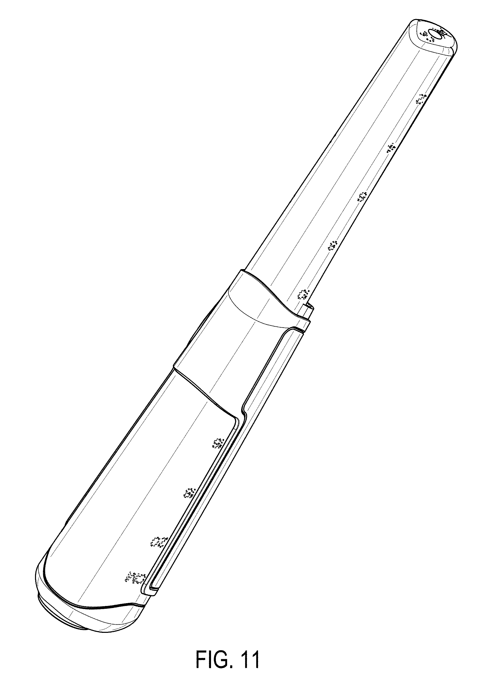
FIG. 11 is a left side perspective view of the pinpointer metal detector shown in FIG. 1 from a bottom-rear direction.
The broken lines in the figure illustrate unclaimed structure and do not constitute a part of the claimed design.
* * * * *
D00000
D00001
D00002
D00003
D00004
D00005
D00006
D00007
D00008
D00009
D00010
D00011
XML
uspto.report is an independent third-party trademark research tool that is not affiliated, endorsed, or sponsored by the United States Patent and Trademark Office (USPTO) or any other governmental organization. The information provided by uspto.report is based on publicly available data at the time of writing and is intended for informational purposes only.
While we strive to provide accurate and up-to-date information, we do not guarantee the accuracy, completeness, reliability, or suitability of the information displayed on this site. The use of this site is at your own risk. Any reliance you place on such information is therefore strictly at your own risk.
All official trademark data, including owner information, should be verified by visiting the official USPTO website at www.uspto.gov. This site is not intended to replace professional legal advice and should not be used as a substitute for consulting with a legal professional who is knowledgeable about trademark law.