Headphones
Karayiannis , et al. Nov
U.S. patent number D867,329 [Application Number D/641,944] was granted by the patent office on 2019-11-19 for headphones. This patent grant is currently assigned to Harman International Industries, Incorporated. The grantee listed for this patent is Harman International Industries, Incorporated. Invention is credited to Effrosini A. Karayiannis, Ryan Ott, Daniel I. Radin.


| United States Patent | D867,329 |
| Karayiannis , et al. | November 19, 2019 |
Headphones
Claims
CLAIM The ornamental design for headphones, as shown and described.
| Inventors: | Karayiannis; Effrosini A. (St. Louis, MO), Radin; Daniel I. (Waterford, CT), Ott; Ryan (North Hollywood, CA) | ||||||||||
|---|---|---|---|---|---|---|---|---|---|---|---|
| Applicant: |
|
||||||||||
| Assignee: | Harman International Industries,
Incorporated (Northridge, CA) |
||||||||||
| Appl. No.: | D/641,944 | ||||||||||
| Filed: | March 26, 2018 |
| Current U.S. Class: | D14/205 |
| Current International Class: | 1401 |
| Field of Search: | ;D14/205,206,250,341 ;D29/112 ;2/209 ;181/129,130,135 ;379/430,431 ;381/380,381,374 ;455/90.3,575.1,569.1 |
References Cited [Referenced By]
U.S. Patent Documents
| 1569398 | January 1926 | Scher |
| 3119904 | January 1964 | Anson |
| D238184 | December 1975 | Ohtoma |
| D254183 | February 1980 | Doodson |
| D286632 | November 1986 | Teunis |
| D302429 | July 1989 | Leer |
| 5113428 | May 1992 | Fitzgerald |
| D328461 | August 1992 | Daido |
| D333137 | February 1993 | Burke |
| 5185807 | February 1993 | Bergin et al. |
| D345981 | April 1994 | Burke |
| D357918 | May 1995 | Doria |
| D376598 | December 1996 | Hayashi |
| D386181 | November 1997 | Fisher |
| 5793865 | August 1998 | Leifer |
| 5793878 | August 1998 | Chang |
| D398309 | September 1998 | Bergin et al. |
| D403128 | December 1998 | Scanlon |
| D405786 | February 1999 | Leifer |
| 6496589 | December 2002 | Pham et al. |
| 6499146 | December 2002 | Bavetta |
| D490419 | May 2004 | Shiue |
| 6880174 | April 2005 | Prokop |
| D576604 | September 2008 | Suzuki |
| D579000 | October 2008 | Rath |
| D585872 | February 2009 | Lee |
| D592639 | May 2009 | Kuh et al. |
| D634732 | March 2011 | Kondo |
| D635958 | April 2011 | Ando et al. |
| D638007 | May 2011 | Chang |
| D641727 | July 2011 | Krauss et al. |
| D658630 | May 2012 | Gondo |
| D663714 | July 2012 | Kang |
| D664116 | July 2012 | Hutchieson |
| D664117 | July 2012 | Tappeiner et al. |
| D678856 | March 2013 | Feng |
| D678857 | March 2013 | Feng |
| D678858 | March 2013 | Feng |
| D686592 | July 2013 | Gondo |
| D696257 | December 2013 | Ward |
| D699216 | February 2014 | Bonahoom et al. |
| D716783 | November 2014 | Loncar |
| D717766 | November 2014 | Mchatet |
| D733091 | June 2015 | Heinonen et al. |
| D737798 | September 2015 | Yoshimura |
| D769842 | October 2016 | Rouffiat |
| D772842 | November 2016 | Sharp et al. |
| D843970 | March 2019 | Ferren |
| D852165 | June 2019 | Karayiannis |
| 300984566 | Dec 2018 | KR | |||
Other References
|
Design U.S. Appl. No. 29/622,793, filed Oct. 19, 2017. cited by applicant . Office Action dated Nov. 6, 2018 in Design U.S. Appl. No. 29/622,793. cited by applicant. |
Primary Examiner: Greene; Paula Allen
Attorney, Agent or Firm: Plumsea Law Group, LLC
Description
FIG. 1 is a perspective view of headphones showing the new design;
FIG. 2 is a front elevation view thereof;
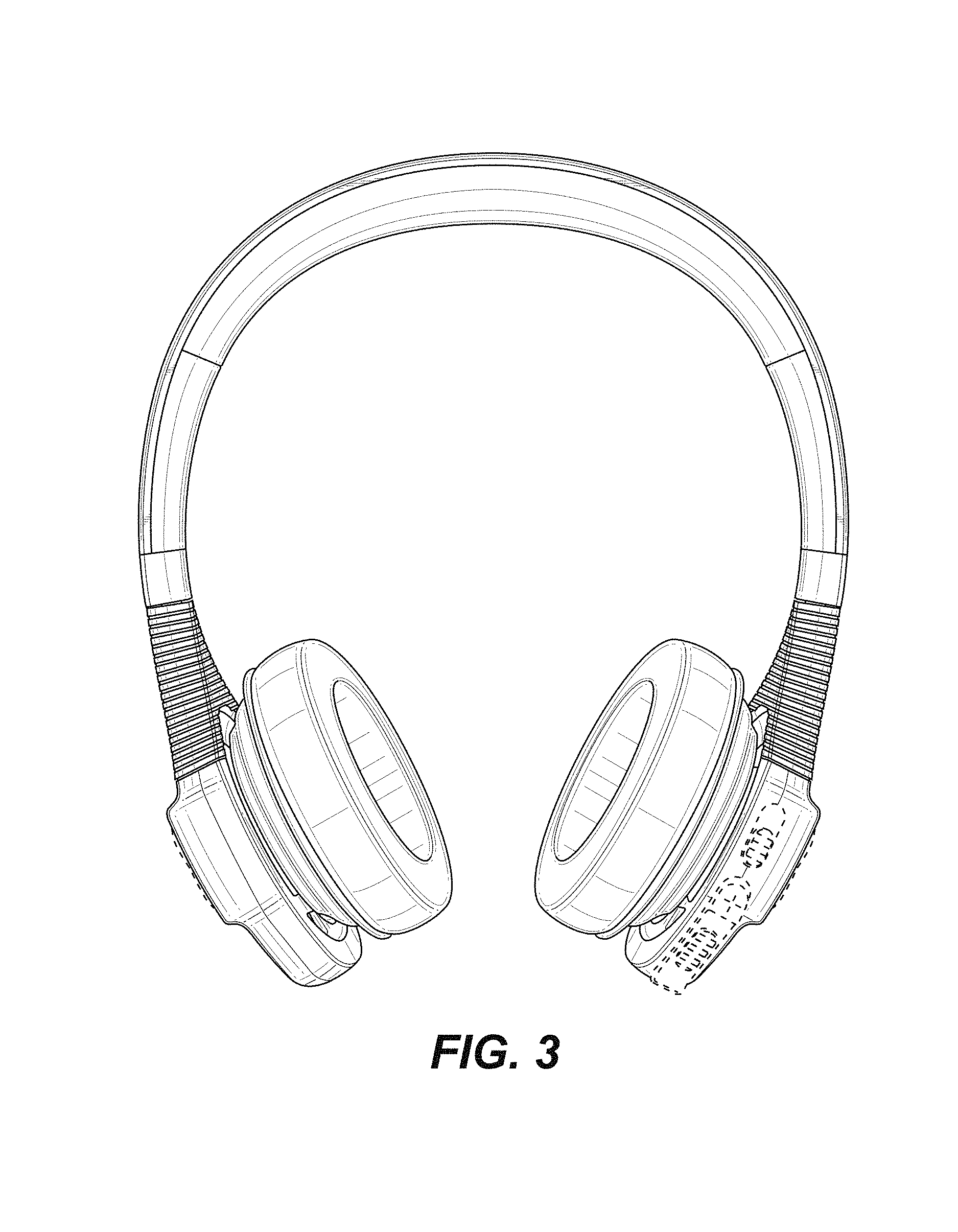
FIG. 3 is a rear elevation view thereof;
FIG. 4 is a side elevation view of one side thereof;
FIG. 5 is a side elevation view of the opposite side thereof;
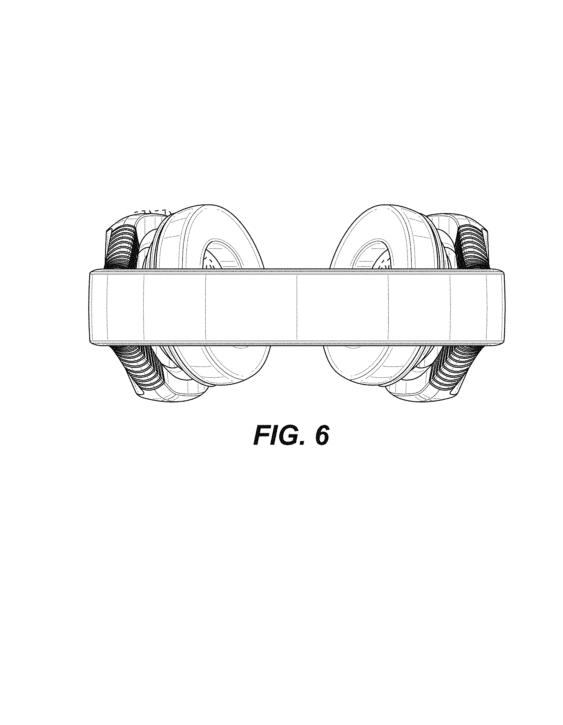
FIG. 6 is a top plan view thereof; and,
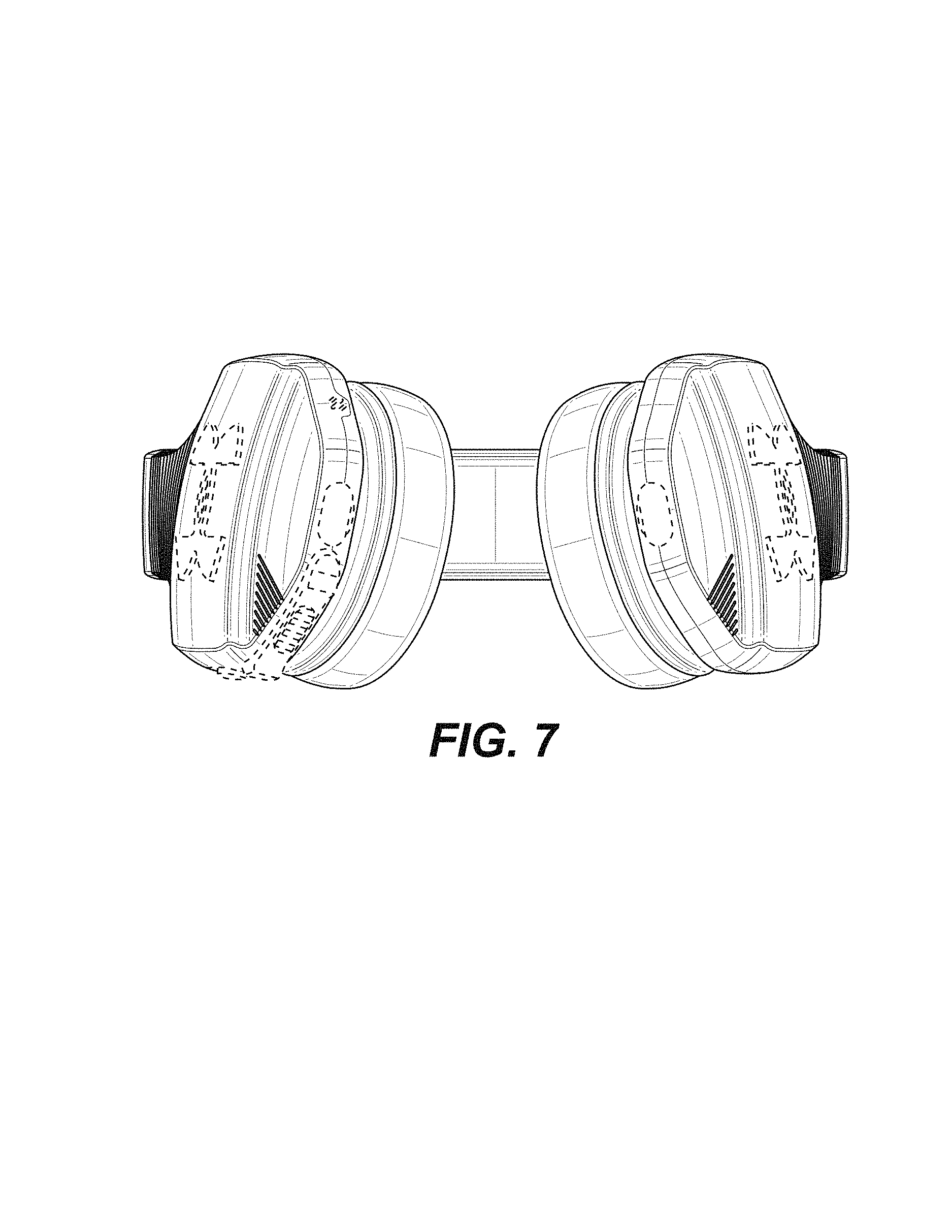
FIG. 7 is a bottom plan view thereof.
The broken line showings form no part of the claimed design.
* * * * *
D00000
D00001
D00002
D00003
D00004
D00005
D00006
D00007
XML
uspto.report is an independent third-party trademark research tool that is not affiliated, endorsed, or sponsored by the United States Patent and Trademark Office (USPTO) or any other governmental organization. The information provided by uspto.report is based on publicly available data at the time of writing and is intended for informational purposes only.
While we strive to provide accurate and up-to-date information, we do not guarantee the accuracy, completeness, reliability, or suitability of the information displayed on this site. The use of this site is at your own risk. Any reliance you place on such information is therefore strictly at your own risk.
All official trademark data, including owner information, should be verified by visiting the official USPTO website at www.uspto.gov. This site is not intended to replace professional legal advice and should not be used as a substitute for consulting with a legal professional who is knowledgeable about trademark law.