End plate for a ceiling fan blade
Horng , et al. No
U.S. patent number D865,939 [Application Number D/617,930] was granted by the patent office on 2019-11-05 for end plate for a ceiling fan blade. This patent grant is currently assigned to Sunonwealth Electric Machine Industry Co., Ltd.. The grantee listed for this patent is Sunonwealth Electric Machine Industry Co., Ltd.. Invention is credited to Alex Horng, Cheng-Wei Lin.


| United States Patent | D865,939 |
| Horng , et al. | November 5, 2019 |
End plate for a ceiling fan blade
Claims
CLAIM The ornamental design for an end plate for a ceiling fan blade, as shown and described.
| Inventors: | Horng; Alex (Kaohsiung, TW), Lin; Cheng-Wei (Kaohsiung, TW) | ||||||||||
|---|---|---|---|---|---|---|---|---|---|---|---|
| Applicant: |
|
||||||||||
| Assignee: | Sunonwealth Electric Machine
Industry Co., Ltd. (Kaohsiung, TW) |
||||||||||
| Appl. No.: | D/617,930 | ||||||||||
| Filed: | September 18, 2017 |
Foreign Application Priority Data
| Sep 4, 2017 [TW] | 106305082 | |||
| Current U.S. Class: | D23/411 |
| Current International Class: | 2303 |
| Field of Search: | ;D23/314,317,324,328,332-337,342,351,352,355,356,359,362,364,370-376,378,379,381-385,411-414 ;D12/214 |
References Cited [Referenced By]
U.S. Patent Documents
| D428984 | August 2000 | Lee |
| 7252478 | August 2007 | Aynsley |
| D672868 | December 2012 | Williams |
| D717936 | November 2014 | Peterson |
| D723678 | March 2015 | Strecker |
| D742499 | November 2015 | Wortman |
| 9360020 | June 2016 | Janecek |
| D771230 | November 2016 | Jones |
| D821560 | June 2018 | Rasmussen |
| D823452 | July 2018 | Rasmussen |
| D834696 | November 2018 | Schulzman |
| 2016/0290357 | October 2016 | Whitley |
| 2019/0072097 | March 2019 | Horng |
| 2019/0072107 | March 2019 | Horng |
Other References
|
Big Ass Fans 2025 Silver and Yellow Shop Ceiling Fan, date first avilable Aug. 24, 2014, site visited Mar. 22, 2019, available at www.amazon.com. cited by examiner. |
Primary Examiner: Brooks; Cathron C
Assistant Examiner: Oum; Sharon S
Attorney, Agent or Firm: Kamrath; Alan D. Mayer & Williams PC
Description
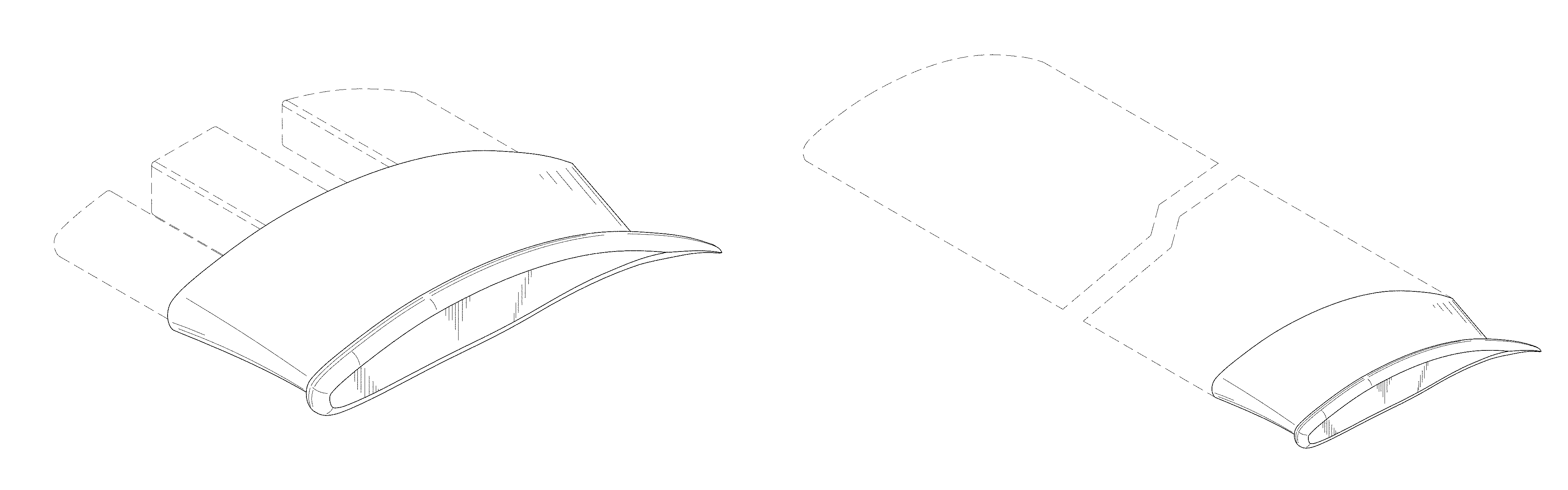
FIG. 1 is a perspective view of an end plate for a ceiling fan blade showing our design;
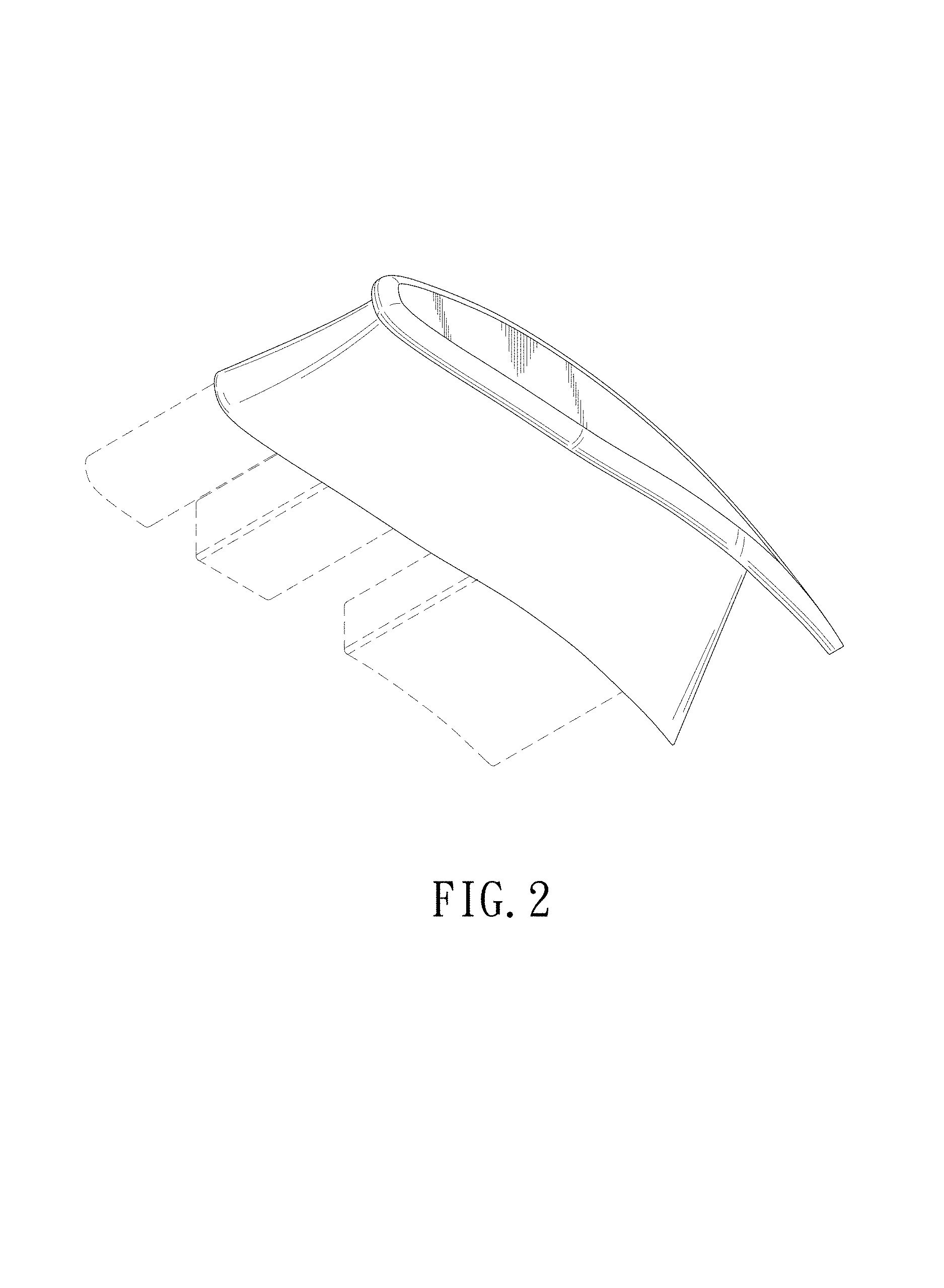
FIG. 2 is another perspective view thereof;
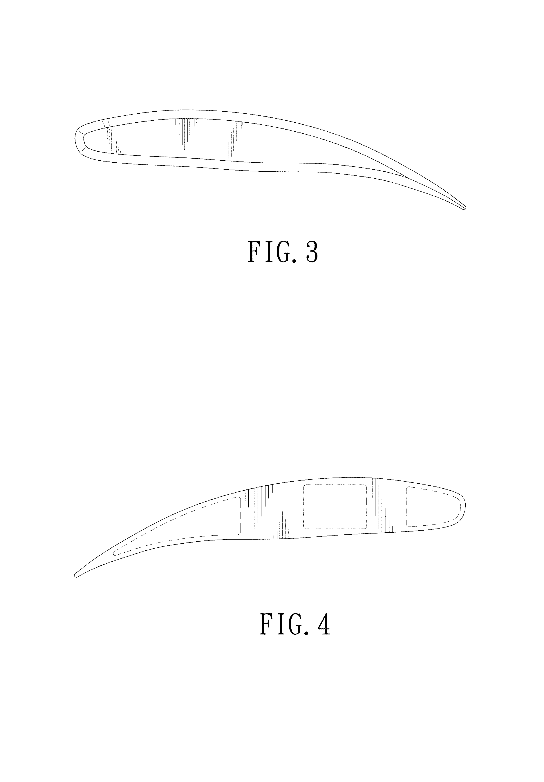
FIG. 3 is a front elevational view thereof;
FIG. 4 is a rear elevational view thereof;
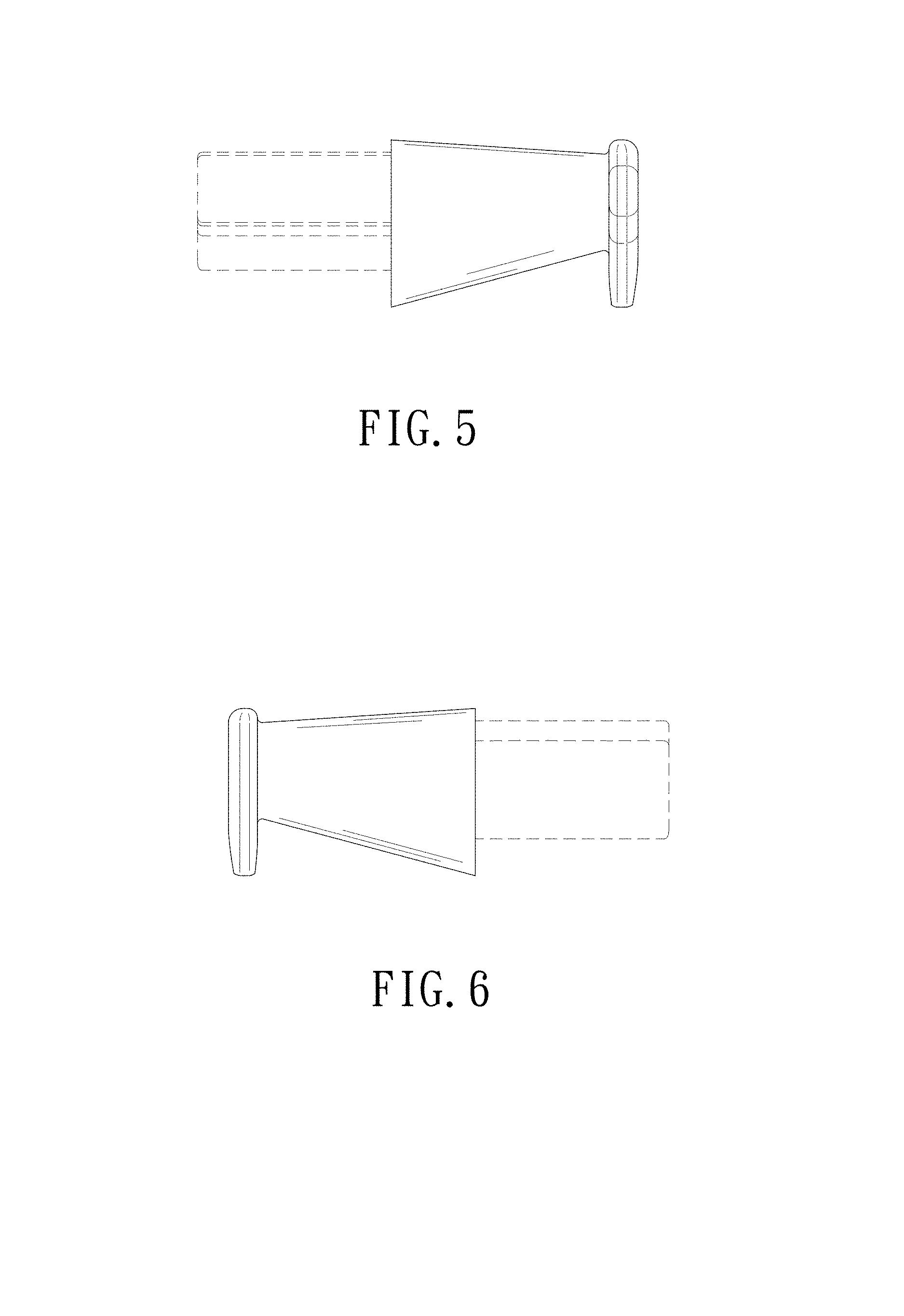
FIG. 5 is a left elevational view thereof;
FIG. 6 is a right elevational view thereof;
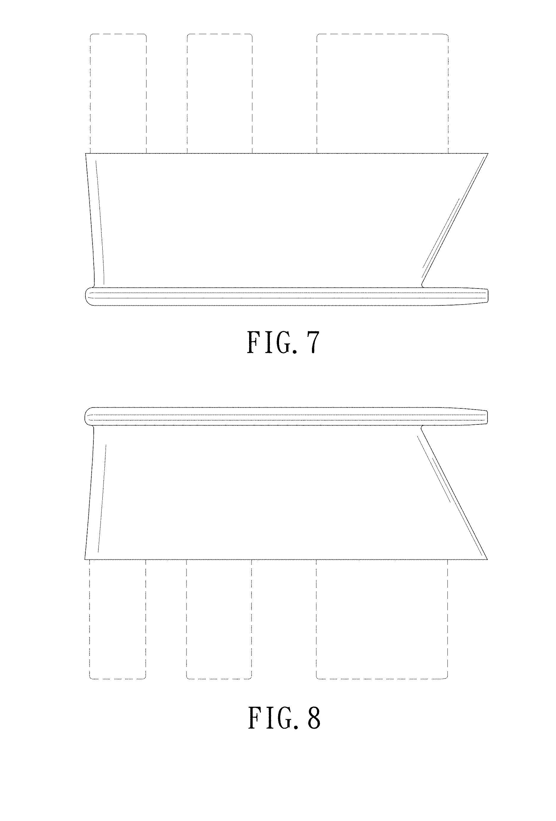
FIG. 7 is a top plan view thereof;
FIG. 8 is a bottom plan view thereof; and,
FIG. 9 is a perspective view thereof, shown in the environment of a ceiling fan blade.
The broken lines illustrate portions of the end plate for a ceiling fan blade and illustrate environmental structure. None of the broken lines form part of the claimed design.
* * * * *
References
D00000
D00001
D00002
D00003
D00004
D00005
D00006
XML
uspto.report is an independent third-party trademark research tool that is not affiliated, endorsed, or sponsored by the United States Patent and Trademark Office (USPTO) or any other governmental organization. The information provided by uspto.report is based on publicly available data at the time of writing and is intended for informational purposes only.
While we strive to provide accurate and up-to-date information, we do not guarantee the accuracy, completeness, reliability, or suitability of the information displayed on this site. The use of this site is at your own risk. Any reliance you place on such information is therefore strictly at your own risk.
All official trademark data, including owner information, should be verified by visiting the official USPTO website at www.uspto.gov. This site is not intended to replace professional legal advice and should not be used as a substitute for consulting with a legal professional who is knowledgeable about trademark law.