Seal member for a pressure vessel
Takahashi , et al. No
U.S. patent number D865,920 [Application Number D/639,432] was granted by the patent office on 2019-11-05 for seal member for a pressure vessel. This patent grant is currently assigned to Valqua, Ltd.. The grantee listed for this patent is Nippon Valqua Industries, Ltd.. Invention is credited to Kenichi Takahashi, Akira Ueda, Sayaka Yoshida, Hirofumi Zushi.


View All Diagrams
| United States Patent | D865,920 |
| Takahashi , et al. | November 5, 2019 |
Seal member for a pressure vessel
Claims
CLAIM The ornamental design for a seal member for a pressure vessel, as shown and described.
| Inventors: | Takahashi; Kenichi (Gojo, JP), Ueda; Akira (Gojo, JP), Zushi; Hirofumi (Gojo, JP), Yoshida; Sayaka (Gojo, JP) | ||||||||||
|---|---|---|---|---|---|---|---|---|---|---|---|
| Applicant: |
|
||||||||||
| Assignee: | Valqua, Ltd. (Tokyo,
JP) |
||||||||||
| Appl. No.: | D/639,432 | ||||||||||
| Filed: | March 6, 2018 |
Related U.S. Patent Documents
| Application Number | Filing Date | Patent Number | Issue Date | ||
|---|---|---|---|---|---|
| 29589722 | Jan 4, 2017 | D836186 | |||
Foreign Application Priority Data
| Jul 5, 2016 [JP] | 2016-014271 | |||
| Jul 5, 2016 [JP] | 2016-014272 | |||
| Jul 5, 2016 [JP] | 2016-014273 | |||
| Current U.S. Class: | D23/269 |
| Current International Class: | 2301 |
| Field of Search: | ;D23/259-260,269,262 ;285/901,42-50 ;417/454 ;277/314-316,351-359,361-364,382,392,394-395,504,553,549,562-563,572,602-603,605-607,609,616-617,623,641-644,650-652 |
References Cited [Referenced By]
U.S. Patent Documents
| D31451 | August 1899 | Norris |
| D32696 | May 1900 | Merwarth |
| 2155457 | April 1939 | West |
| 6523833 | February 2003 | Ishigaki et al. |
| 6557857 | May 2003 | Goodman |
| D517679 | March 2006 | Stout, Jr. et al. |
| D518885 | April 2006 | Stout, Jr. |
| 7347224 | March 2008 | Nohara et al. |
| 7584934 | September 2009 | Eichinger |
| D614271 | April 2010 | Weston |
| 7828302 | November 2010 | Hurlbert |
| D646764 | October 2011 | Rusconi |
| 9291266 | March 2016 | Yu |
| D755356 | May 2016 | Vaseleniuck et al. |
| D785144 | April 2017 | Kitagawa |
| 9611940 | April 2017 | Khan et al. |
| D802723 | November 2017 | Miyamoto |
| 2003/0160452 | August 2003 | Mattsson et al. |
| 2008/0012238 | January 2008 | Kapcoe et al. |
| 2009/0045371 | February 2009 | Kamibayashiyama |
| 2009/0289450 | November 2009 | Bluhm |
| 2010/0264606 | October 2010 | Hayashi |
| 2012/0223488 | September 2012 | Kim |
| 2014/0070494 | March 2014 | Winkelmann et al. |
| 2014/0175310 | June 2014 | Coppola et al. |
| 2015/0176713 | June 2015 | Khan |
| 2015/0184761 | July 2015 | Kusakabe |
| 2017/0211706 | July 2017 | Amir et al. |
| 2018/0163868 | June 2018 | Ishigami |
| 301169536 | Apr 2010 | CN | |||
| D2093567 | Jul 1990 | JP | |||
| D127507 | Feb 2009 | TW | |||
| D127508 | Feb 2009 | TW | |||
Assistant Examiner: Wierenga; Amy C
Attorney, Agent or Firm: The Webb Law Firm
Description
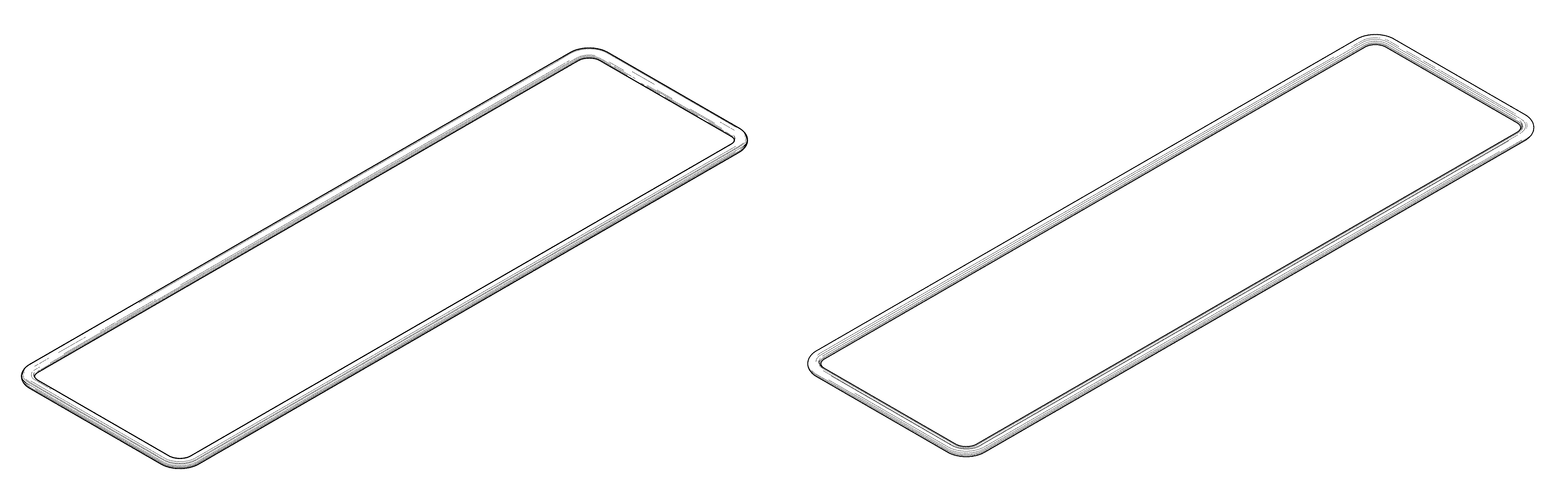
FIG. 1 is a top view of a seal member for a pressure vessel showing our new design according to a first embodiment of the invention;
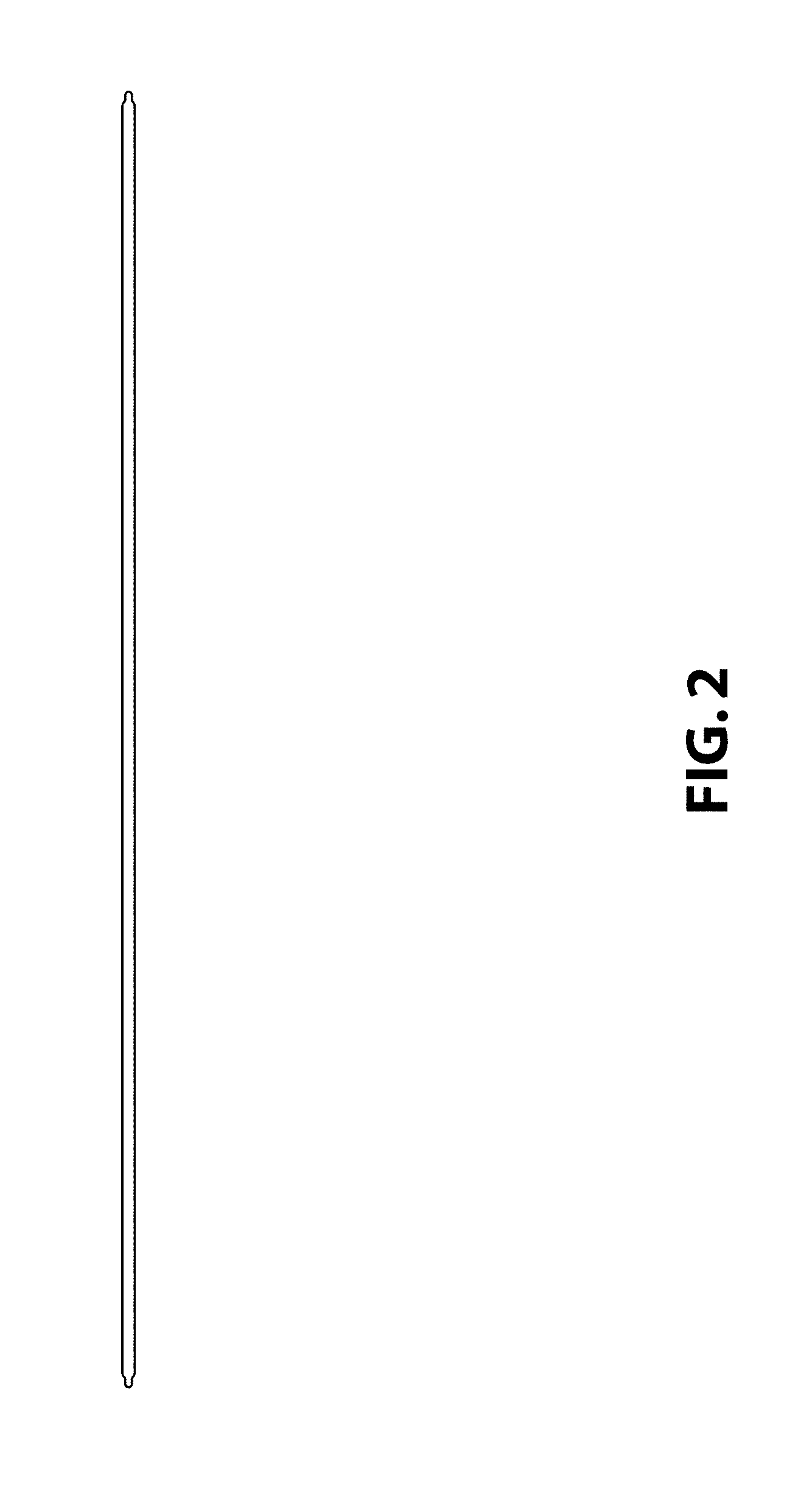
FIG. 2 is a front elevation view thereof;
FIG. 3 is a right side elevation view thereof;
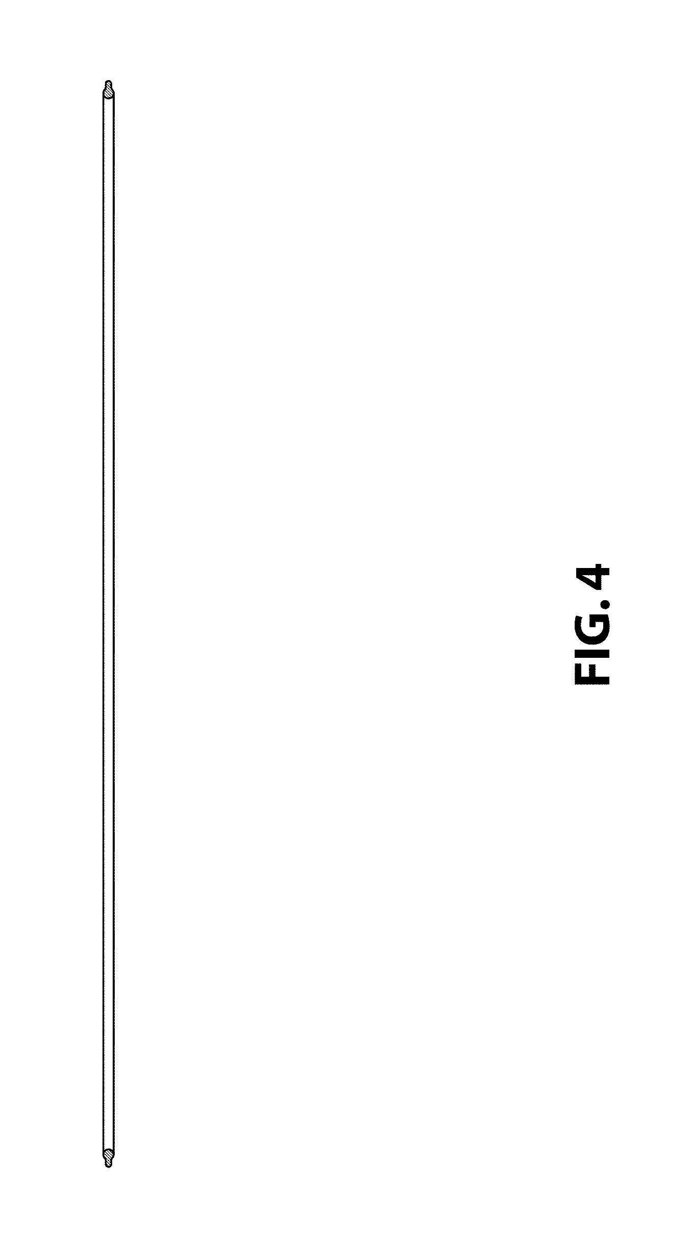
FIG. 4 is a cross-sectional view thereof taken along lines 4-4 shown in FIG. 1;
FIG. 5 is an enlarged cross-sectional view of a portion thereof defined by area 5-5 shown in FIG. 1;
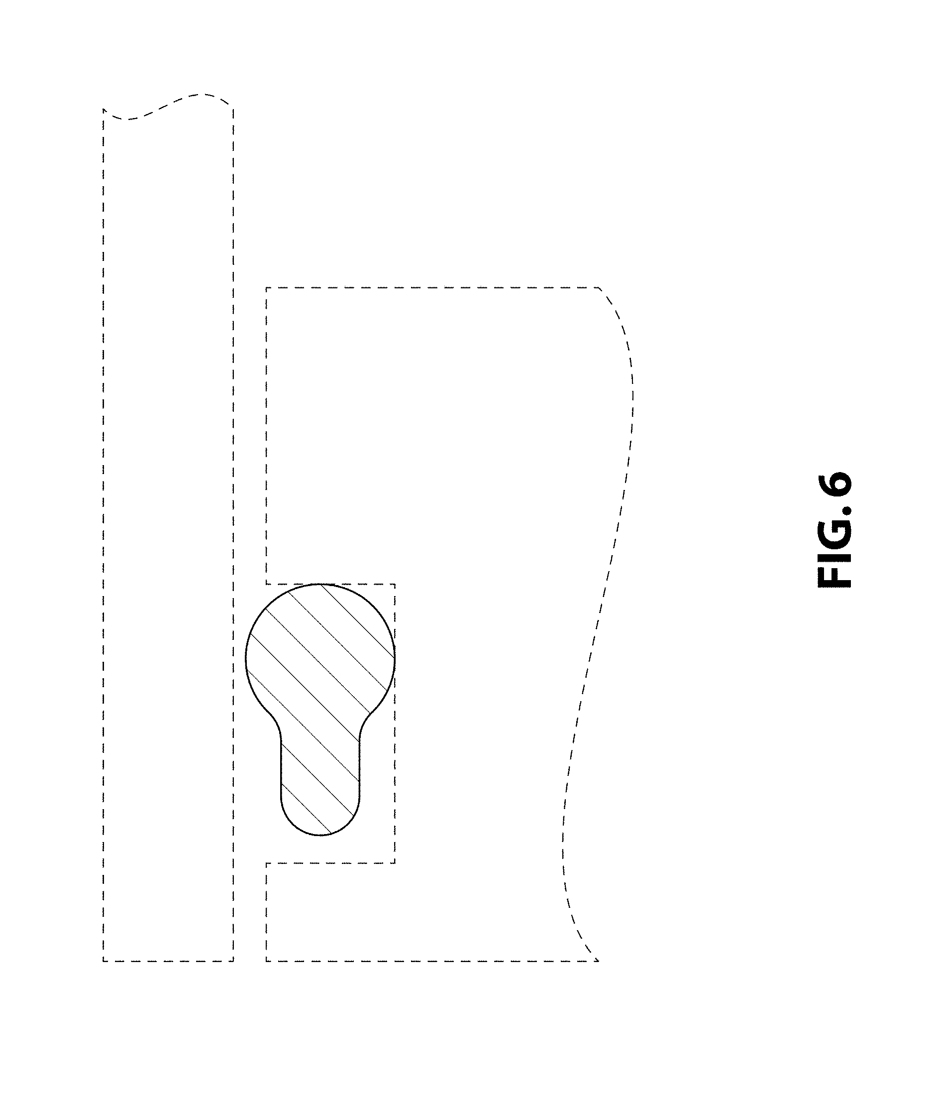
FIG. 6 is an enlarged cross-sectional view of a portion thereof in a condition of use;
FIG. 7 is a perspective view thereof;
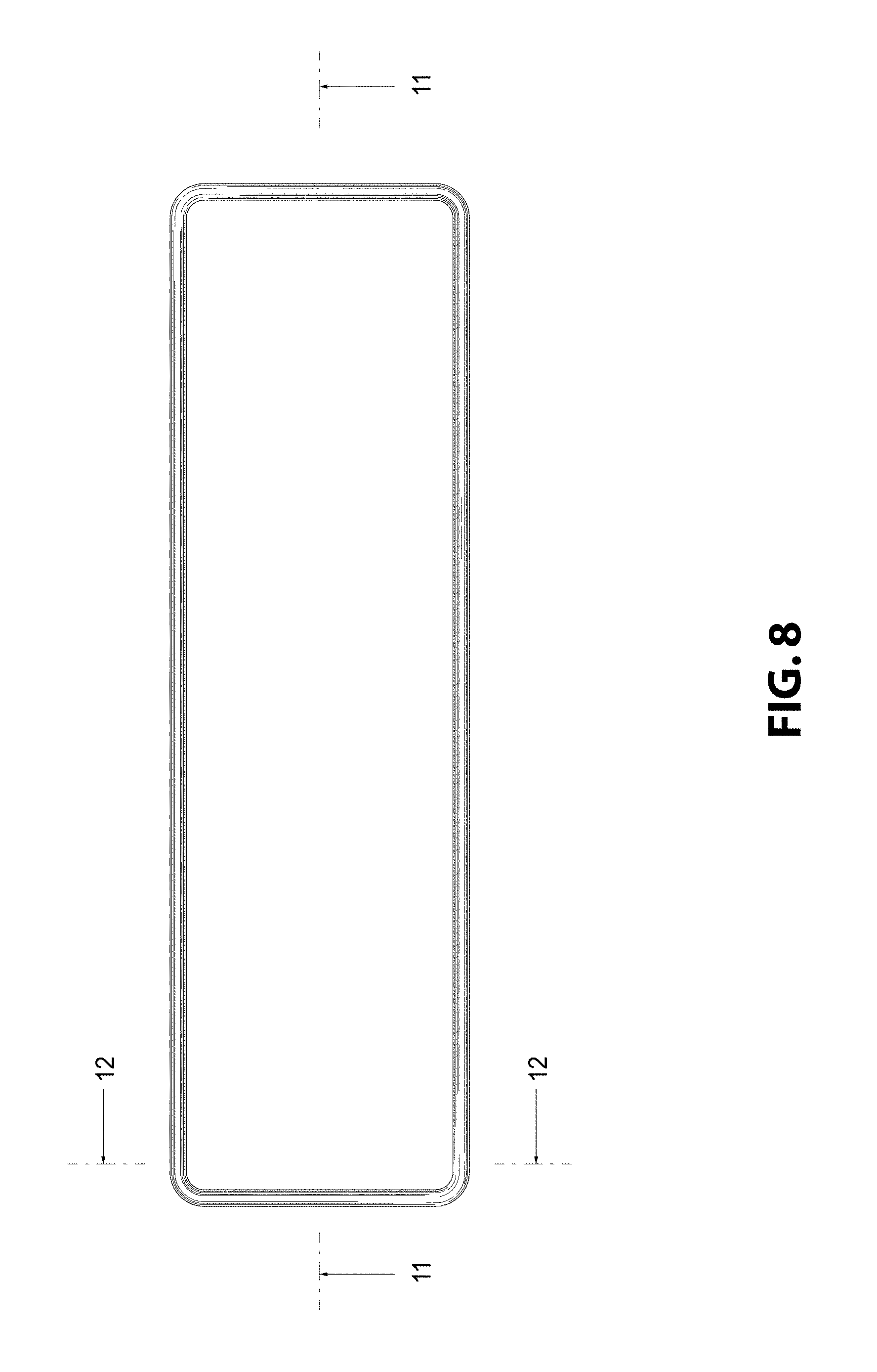
FIG. 8 is a top view of a seal member for a pressure vessel showing our new design according to a second embodiment of the invention;
FIG. 9 is a front elevation view thereof;
FIG. 10 is a right side elevation view thereof;
FIG. 11 is a cross-sectional view thereof taken along lines 11-11 shown in FIG. 8;
FIG. 12 is an enlarged cross-sectional view of a portion thereof defined by area 12-12 shown in FIG. 8;
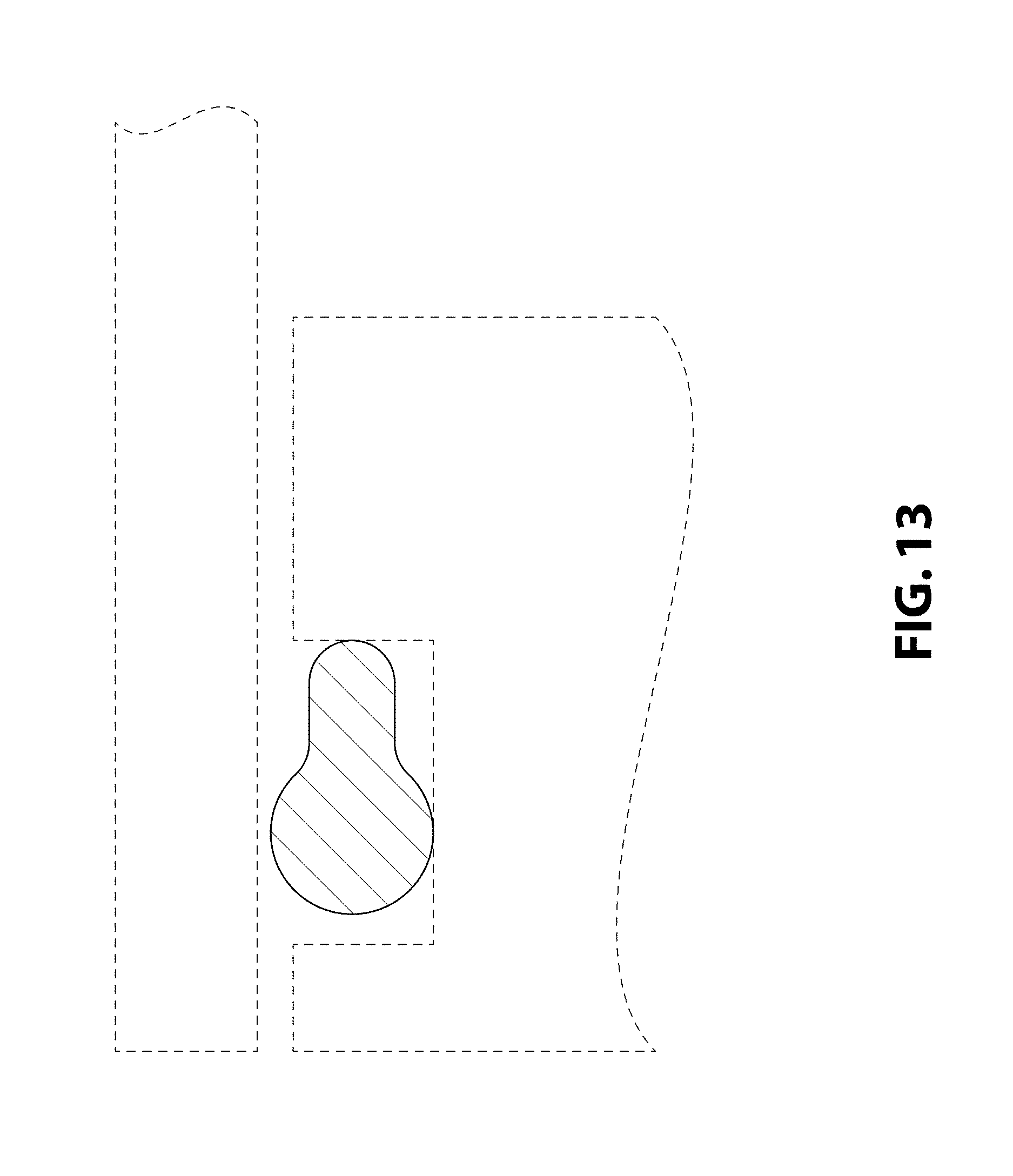
FIG. 13 is an enlarged cross-sectional view of a portion thereof in a condition of use; and,
FIG. 14 is a perspective view thereof.
The bottom, rear elevation, and left side elevation views for each embodiment of the seal member for a pressure vessel are omitted as they are identical in appearance to the top, front elevation, and right side elevation views, respectively, for each embodiment.
The dot dash broken lines shown in FIGS. 5 and 12 indicate cutoff boundaries for the enlarged detailed portion views and form no part of the claim.
The evenly dashed lines shown in FIGS. 6 and 13 depict environmental subject matter that forms no part of the claim.
* * * * *
D00000
D00001
D00002
D00003
D00004
D00005
D00006
D00007
D00008
D00009
D00010
D00011
D00012

D00013
D00014

XML
uspto.report is an independent third-party trademark research tool that is not affiliated, endorsed, or sponsored by the United States Patent and Trademark Office (USPTO) or any other governmental organization. The information provided by uspto.report is based on publicly available data at the time of writing and is intended for informational purposes only.
While we strive to provide accurate and up-to-date information, we do not guarantee the accuracy, completeness, reliability, or suitability of the information displayed on this site. The use of this site is at your own risk. Any reliance you place on such information is therefore strictly at your own risk.
All official trademark data, including owner information, should be verified by visiting the official USPTO website at www.uspto.gov. This site is not intended to replace professional legal advice and should not be used as a substitute for consulting with a legal professional who is knowledgeable about trademark law.