Shaft assembly for surgical stapler
Auld , et al. Oc
U.S. patent number D865,174 [Application Number D/608,977] was granted by the patent office on 2019-10-29 for shaft assembly for surgical stapler. This patent grant is currently assigned to Ethicon LLC. The grantee listed for this patent is ETHICON LLC. Invention is credited to Michael D. Auld, Sol Posada, Frederick E. Shelton, IV, Brett E. Swensgard, Michael J. Vendely.


View All Diagrams
| United States Patent | D865,174 |
| Auld , et al. | October 29, 2019 |
Shaft assembly for surgical stapler
Claims
CLAIM The ornamental design for a shaft assembly for surgical stapler, as shown and described.
| Inventors: | Auld; Michael D. (Blue Ash, OH), Swensgard; Brett E. (West Chester, OH), Posada; Sol (Cincinnati, OH), Vendely; Michael J. (Lebanon, OH), Shelton, IV; Frederick E. (Hillsboro, OH) | ||||||||||
|---|---|---|---|---|---|---|---|---|---|---|---|
| Applicant: |
|
||||||||||
| Assignee: | Ethicon LLC (Guaynabo,
PR) |
||||||||||
| Appl. No.: | D/608,977 | ||||||||||
| Filed: | June 27, 2017 |
| Current U.S. Class: | D24/145 |
| Current International Class: | 2402 |
| Field of Search: | ;D24/127,133,143,145,146,147 ;227/175.1,179.1 |
References Cited [Referenced By]
U.S. Patent Documents
| D541418 | April 2007 | Schechter |
| D631964 | February 2011 | Miles |
| D680646 | April 2013 | Hunt |
| D681202 | April 2013 | Hunt |
| D700325 | February 2014 | Nalagatla |
| D800904 | October 2017 | Leimbach |
| 10111679 | October 2018 | Baber |
| 2014/0367448 | December 2014 | Cappola |
| 2016/0270788 | September 2016 | Czernik |
| 2018/0168592 | June 2018 | Overmyer |
| 2018/0168597 | June 2018 | Fanelli |
| 2018/0168634 | June 2018 | Harris |
| 2018/0303481 | October 2018 | Shelton, IV |
| 2018/0317921 | November 2018 | Cabrera |
| 2018/0360445 | December 2018 | Shelton, IV |
| 2019/0000471 | January 2019 | Shelton, IV |
| 2019/0015097 | January 2019 | Williams |
| 2019/0059892 | February 2019 | Miller |
| 3064141 | Sep 2016 | EP | |||
| 3178413 | Jun 2017 | EP | |||
Assistant Examiner: Samuel; Clint A
Attorney, Agent or Firm: Frost Brown Todd LLC
Description
FIG. 1 is a front perspective view of a shaft assembly for surgical stapler, showing our new design;
FIG. 2 is a rear perspective view of the shaft assembly of FIG. 1;
FIG. 3 is a right elevational view of the shaft assembly of FIG. 1;
FIG. 4 is a left elevational view of the shaft assembly of FIG. 1;
FIG. 5 is a front elevational view of the shaft assembly of FIG. 1;
FIG. 6 is a rear elevational view of the shaft assembly of FIG. 1;
FIG. 7 is a top plan view of the shaft assembly of FIG. 1;
FIG. 8 is a bottom plan view of the shaft assembly of FIG. 1;
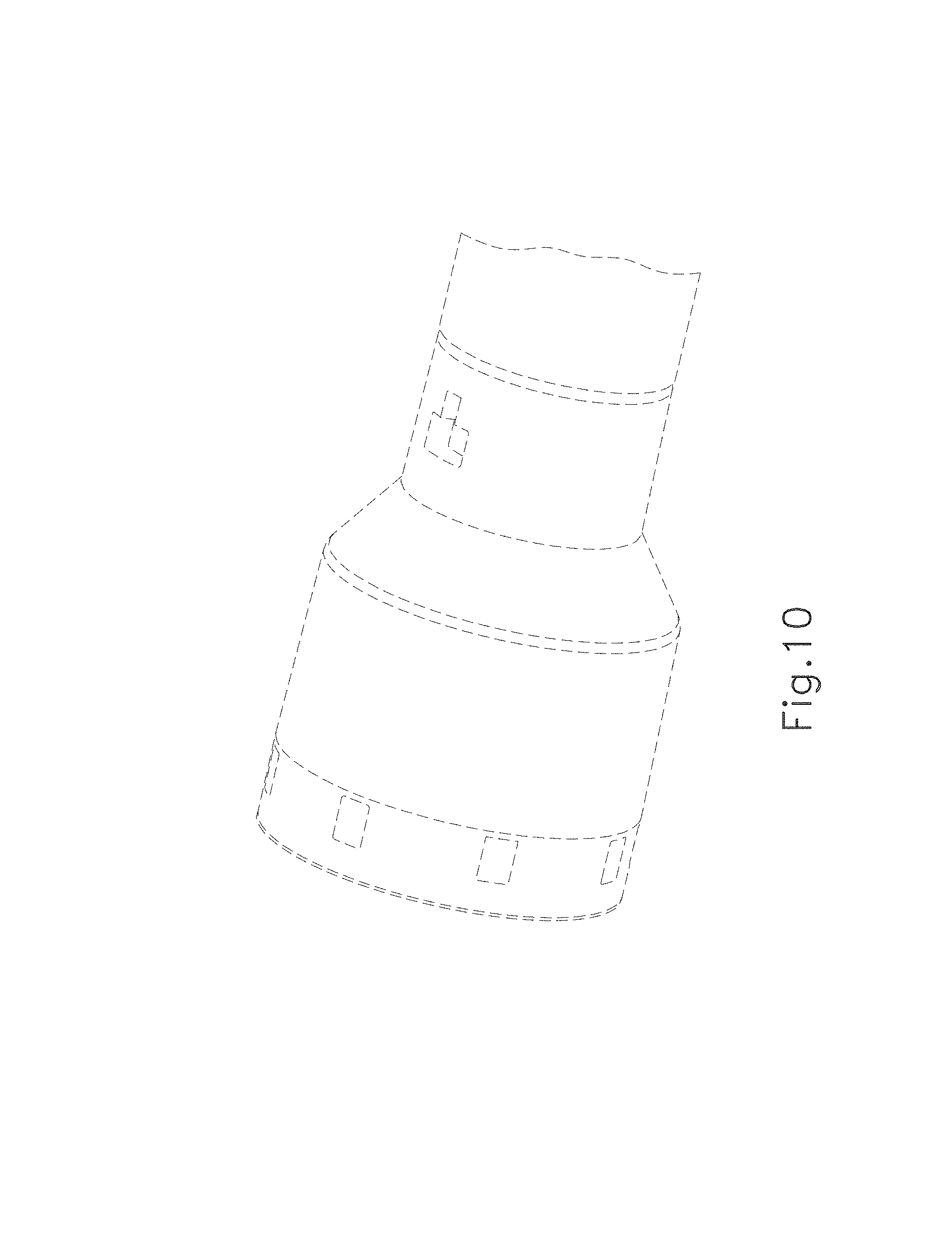
FIG. 9 is an enlarged perspective view of a distal portion of the shaft assembly of FIG. 1, the portion being indicated by the broken line circle labeled as "FIG. 9" in FIG. 1;
FIG. 10 is another enlarged perspective view of the distal portion of FIG. 9;
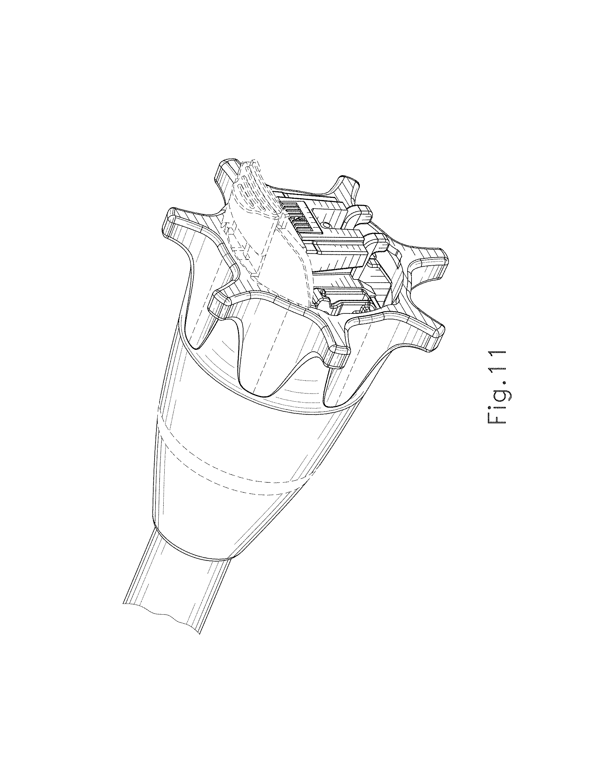
FIG. 11 is an enlarged perspective view of a proximal portion of the shaft assembly of FIG. 1, the portion being indicated by the broken line circle labeled as "FIG. 11" in FIG. 2; and,
FIG. 12 is another enlarged perspective view of the proximal portion of FIG. 11.
The distal and proximal shaft assembly portions shown in broken lines are unclaimed environment, and form no part of the claimed design.
* * * * *
D00000
D00001
D00002
D00003
D00004
D00005
D00006
D00007
D00008
D00009
D00010
D00011
XML
uspto.report is an independent third-party trademark research tool that is not affiliated, endorsed, or sponsored by the United States Patent and Trademark Office (USPTO) or any other governmental organization. The information provided by uspto.report is based on publicly available data at the time of writing and is intended for informational purposes only.
While we strive to provide accurate and up-to-date information, we do not guarantee the accuracy, completeness, reliability, or suitability of the information displayed on this site. The use of this site is at your own risk. Any reliance you place on such information is therefore strictly at your own risk.
All official trademark data, including owner information, should be verified by visiting the official USPTO website at www.uspto.gov. This site is not intended to replace professional legal advice and should not be used as a substitute for consulting with a legal professional who is knowledgeable about trademark law.