Electronic device
Akana , et al. Oc
U.S. patent number D864,950 [Application Number D/586,519] was granted by the patent office on 2019-10-29 for electronic device. This patent grant is currently assigned to Apple Inc.. The grantee listed for this patent is Apple Inc.. Invention is credited to Jody Akana, Bartley K. Andre, Jeremy Bataillou, Daniel J. Coster, Daniele De Iuliis, M. Evans Hankey, Julian Hoenig, Richard P. Howarth, Jonathan P. Ive, Duncan Robert Kerr, Shin Nishibori, Matthew Dean Rohrbach, Peter Russell-Clarke, Christopher J. Stringer, Eugene Antony Whang, Rico Zorkendorfer.
| United States Patent | D864,950 |
| Akana , et al. | October 29, 2019 |
Electronic device
Claims
CLAIM The ornamental design for an electronic device, as shown and described.
| Inventors: | Akana; Jody (San Francisco, CA), Andre; Bartley K. (Palo Alto, CA), Bataillou; Jeremy (San Francisco, CA), Coster; Daniel J. (San Francisco, CA), De Iuliis; Daniele (San Francisco, CA), Hankey; M. Evans (San Francisco, CA), Hoenig; Julian (San Francisco, CA), Howarth; Richard P. (San Francisco, CA), Ive; Jonathan P. (San Francisco, CA), Kerr; Duncan Robert (San Francisco, CA), Nishibori; Shin (Kailua, HI), Rohrbach; Matthew Dean (San Francisco, CA), Russell-Clarke; Peter (San Francisco, CA), Stringer; Christopher J. (Woodside, CA), Whang; Eugene Antony (San Francisco, CA), Zorkendorfer; Rico (San Francisco, CA) | ||||||||||
|---|---|---|---|---|---|---|---|---|---|---|---|
| Applicant: |
|
||||||||||
| Assignee: | Apple Inc. (Cupertino,
CA) |
||||||||||
| Appl. No.: | D/586,519 | ||||||||||
| Filed: | December 5, 2016 |
Related U.S. Patent Documents
| Application Number | Filing Date | Patent Number | Issue Date | ||
|---|---|---|---|---|---|
| 29493571 | Jun 11, 2014 | D773453 | |||
| 29423180 | Jun 17, 2014 | D707223 | |||
| Current U.S. Class: | D14/341 |
| Current International Class: | 1402 |
| Field of Search: | ;D14/341-347,137,138AA,138R,138C,138G,496,203.1,203.3,203.7,426,129,130,420,147,218,247-248,389,388,315-318 ;D10/65,104.1 ;D18/6-7 ;D21/324,329,330 ;455/556.1,556.2,566,575.1,90.3 ;379/433.04,433.01,433.06,916 ;345/173,901,905 ;361/679.26,679.27,679.3,679.55,679.56,680-686 ;248/917-924 ;348/373,376 ;D19/60 |
References Cited [Referenced By]
U.S. Patent Documents
| 5600800 | February 1997 | Kikinis et al. |
| D399864 | October 1998 | Gotham |
| D456023 | April 2002 | Andre et al. |
| D502173 | February 2005 | Jung et al. |
| D514090 | January 2006 | Carbone et al. |
| 7042712 | May 2006 | Ghosh et al. |
| D557256 | December 2007 | Joseph |
| D561782 | February 2008 | Kim |
| D574019 | July 2008 | Amit et al. |
| D580387 | November 2008 | Andre et al. |
| D602015 | October 2009 | Andre et al. |
| D602486 | October 2009 | Andre et al. |
| D627778 | November 2010 | Akana et al. |
| D645835 | September 2011 | Lee et al. |
| D646249 | October 2011 | Kim et al. |
| D651189 | December 2011 | Tsai et al. |
| D653642 | February 2012 | Han |
| D653645 | February 2012 | Park |
| D654049 | February 2012 | Chung |
| D654460 | February 2012 | Kim et al. |
| D654900 | February 2012 | Jung |
| D664531 | July 2012 | Akana et al. |
| D670286 | November 2012 | Akana et al. |
| D673561 | January 2013 | Hyun et al. |
| D674383 | January 2013 | Andre et al. |
| D678881 | March 2013 | Groene et al. |
| D682333 | May 2013 | Kim et al. |
| D684553 | June 2013 | Kim et al. |
| D684571 | June 2013 | Akana |
| D707223 | June 2014 | Akana |
| D714254 | September 2014 | Miyazaki et al. |
| D715794 | October 2014 | Zhou et al. |
| D717801 | November 2014 | Rantala et al. |
| D718271 | November 2014 | McTague et al. |
| D721063 | January 2015 | Chung |
| D721355 | January 2015 | Chung |
| D724078 | March 2015 | Andre et al. |
| D730361 | May 2015 | Akana et al. |
| D733146 | June 2015 | Akana et al. |
| D743391 | November 2015 | Akana |
| D747310 | January 2016 | Akana |
| D748091 | January 2016 | Akana |
| D748621 | February 2016 | Akana |
| D749563 | February 2016 | Akana |
| D753101 | April 2016 | Akana |
| D754125 | April 2016 | Akana |
| D760217 | June 2016 | Akana |
| D766889 | September 2016 | Akana |
| D771623 | November 2016 | Akana |
| D772865 | November 2016 | Akana |
| D773453 | December 2016 | Akana |
| D778905 | February 2017 | Akana |
| D779484 | February 2017 | Akana |
| D783602 | April 2017 | Akana |
| D784324 | April 2017 | Akana |
| D800716 | October 2017 | Akana |
| D803209 | November 2017 | Akana |
| D809507 | February 2018 | Akana |
| 2004/0242288 | December 2004 | Balle et al. |
| 2006/0281501 | December 2006 | Zuo et al. |
| 2009/0245564 | October 2009 | Mittleman et al. |
| 2009/0247244 | October 2009 | Mittleman et al. |
| 2010/0105452 | April 2010 | Shin et al. |
| 332935 | Sep 2010 | AU | |||
| DI7004334-5 | Dec 2011 | BR | |||
| 200801680 | Jun 2008 | CL | |||
| 200901887 | Sep 2009 | CL | |||
| 200801681 | Nov 2009 | CL | |||
| 200902212 | Dec 2009 | CL | |||
| 200902213 | Dec 2009 | CL | |||
| 200902214 | Dec 2009 | CL | |||
| 201000859 | Aug 2010 | CL | |||
| 201000909 | Aug 2010 | CL | |||
| 001016802-0001 | Jan 2009 | EP | |||
| 001098149-0001 | Apr 2009 | EP | |||
| 001183461-0002 | Jan 2010 | EP | |||
| 001668781-0001 | Feb 2010 | EP | |||
| 001694712-0001 | Apr 2010 | EP | |||
| 30-0424148 | Sep 2006 | KR | |||
| 30-0441230-1 | Feb 2007 | KR | |||
| 30-0441230-2 | Aug 2007 | KR | |||
| 30-0474260 | Dec 2007 | KR | |||
| 30-0529167 | May 2009 | KR | |||
| 30-0533504 | Jul 2009 | KR | |||
| 30-0546031 | Nov 2009 | KR | |||
| 30-0553546 | Feb 2010 | KR | |||
| D106137 | Aug 2005 | TW | |||
| D123283 | Jun 2008 | TW | |||
| D126454 | Dec 2008 | TW | |||
| D126838 | Jan 2009 | TW | |||
| D126996 | Apr 2009 | TW | |||
| D126997 | Apr 2009 | TW | |||
| D129176 | Jun 2009 | TW | |||
| D131556 | Oct 2009 | TW | |||
| D132490 | Dec 2009 | TW | |||
| D139493 | Mar 2011 | TW | |||
Attorney, Agent or Firm: Sterne, Kessler, Goldstein & Fox P.L.L.C.
Description
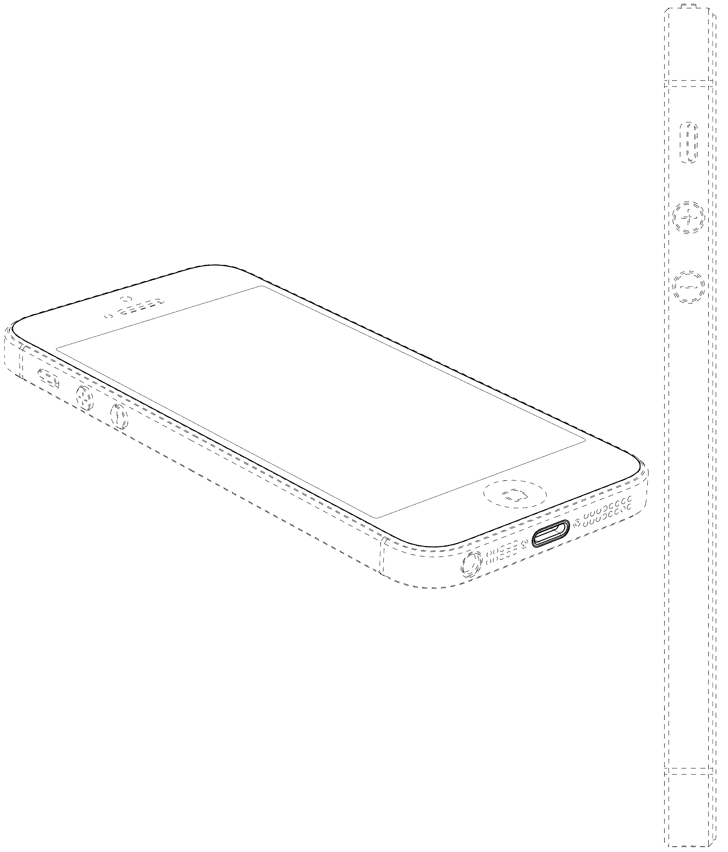
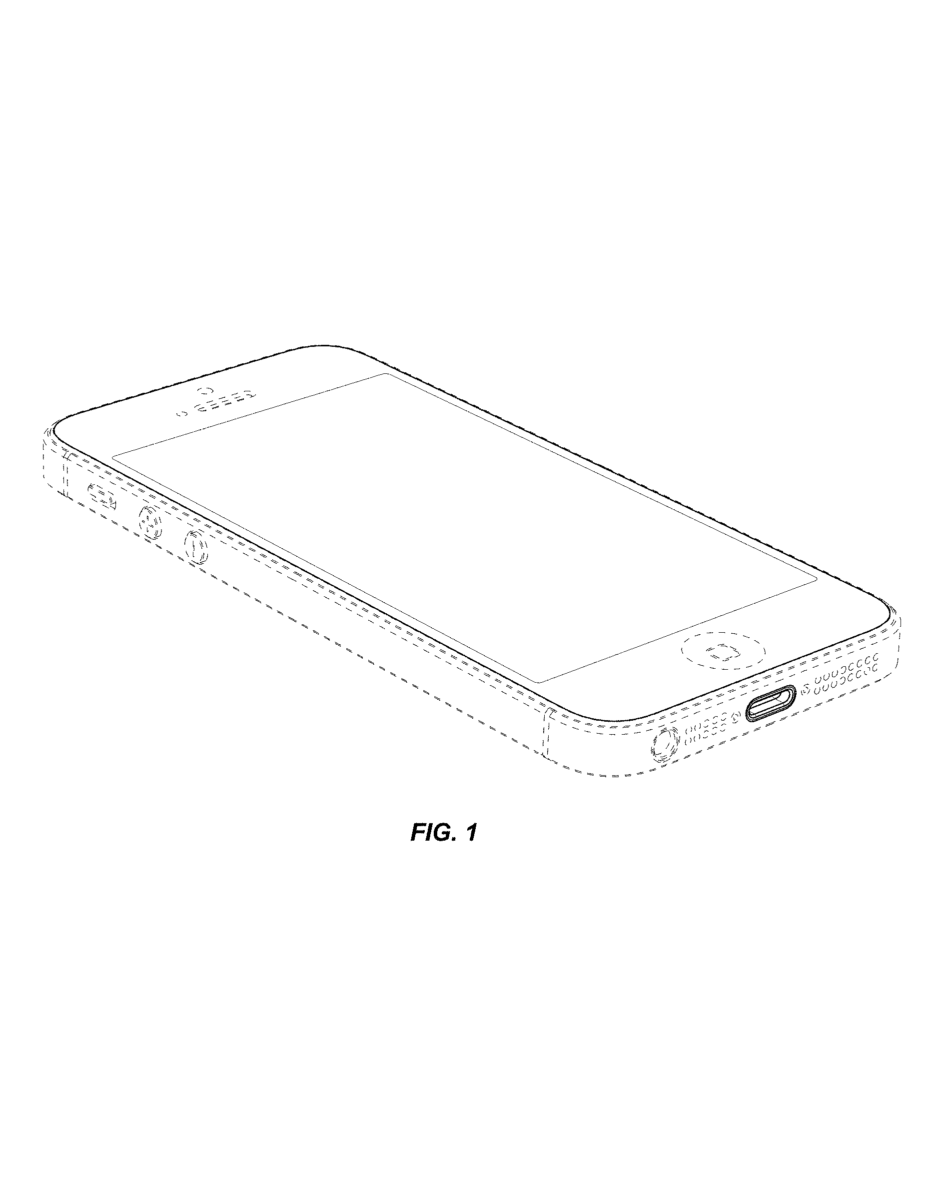
FIG. 1 is a bottom front perspective view of an electronic device showing the claimed design;
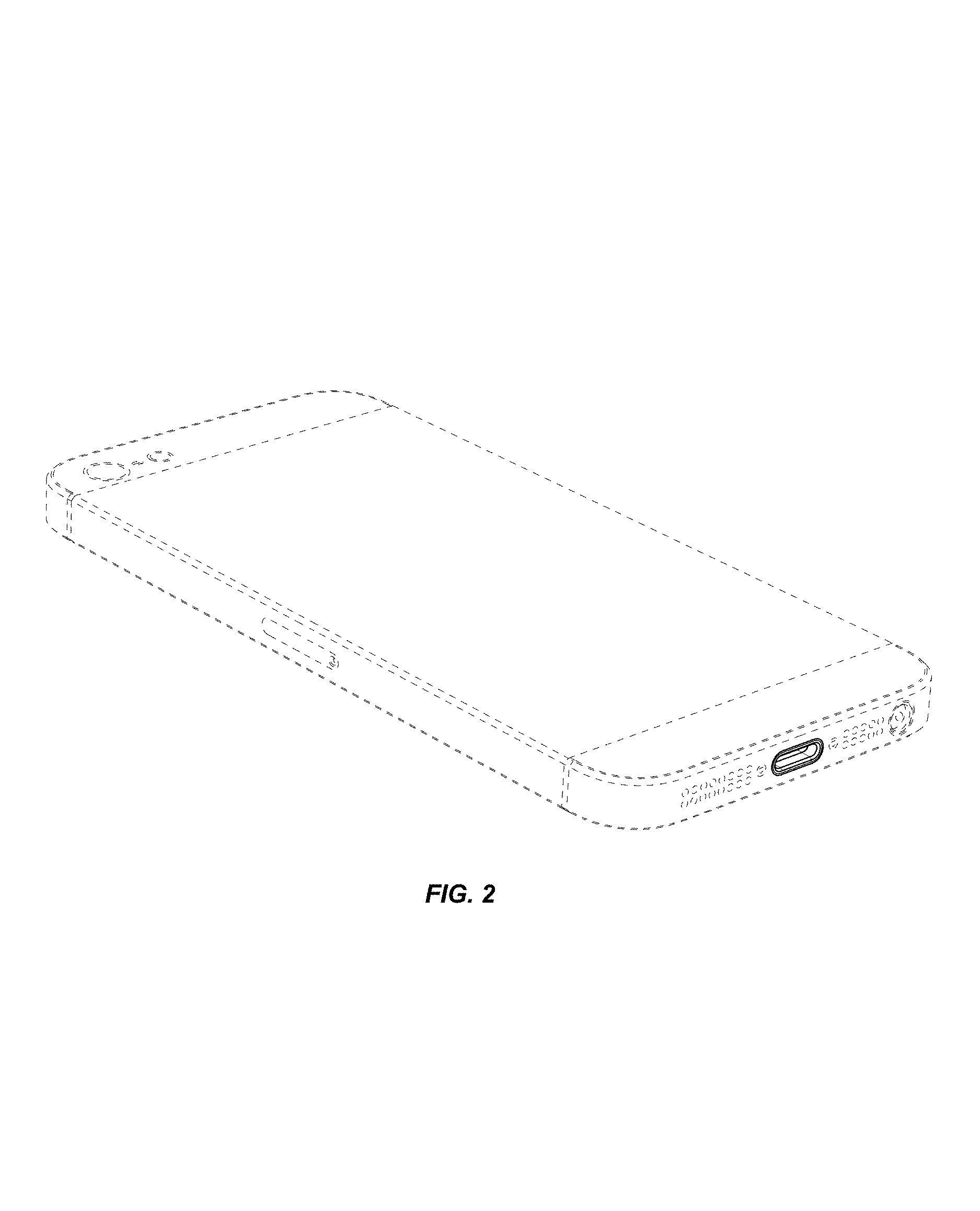
FIG. 2 is a bottom rear perspective view thereof;
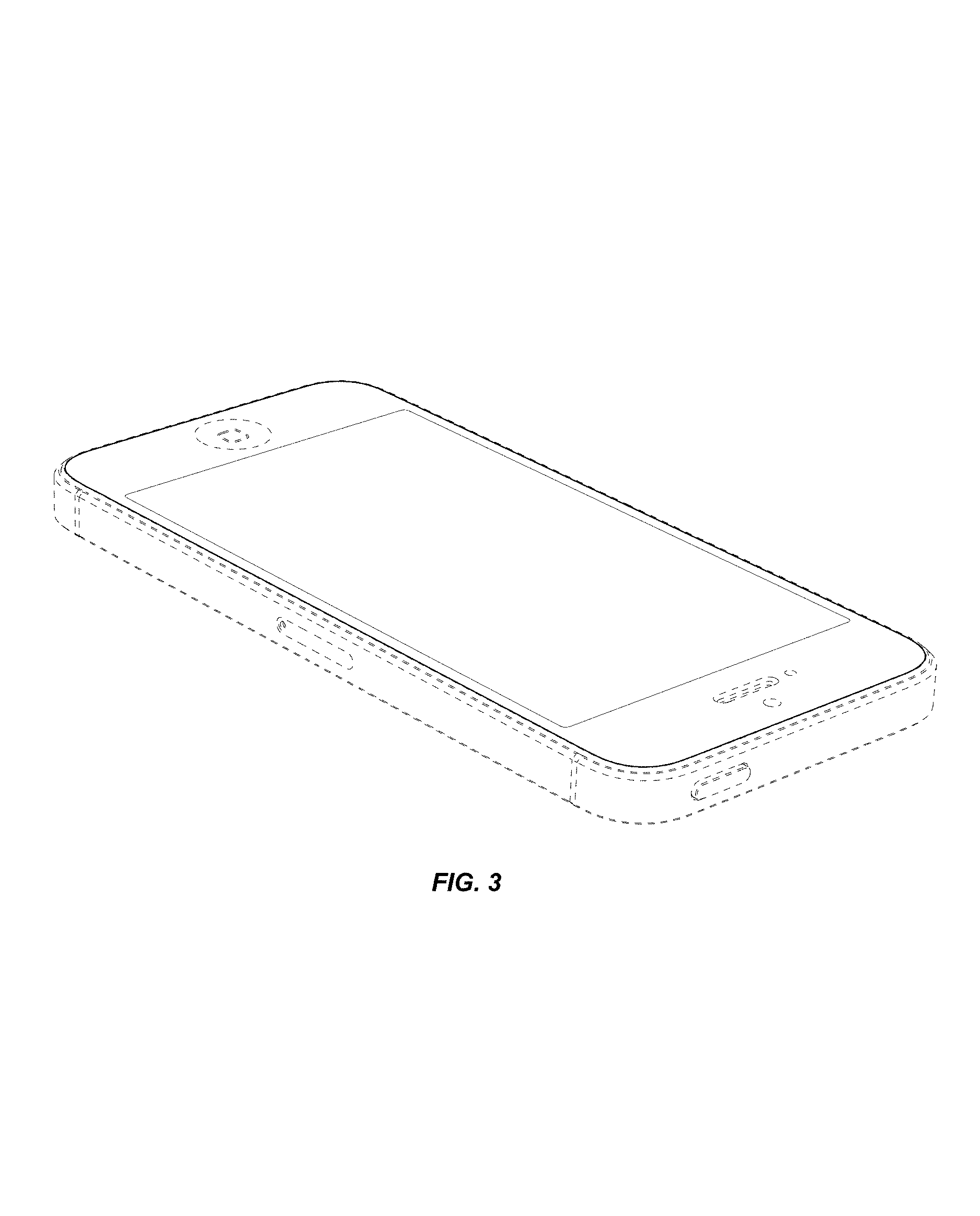
FIG. 3 is a top front perspective view thereof;
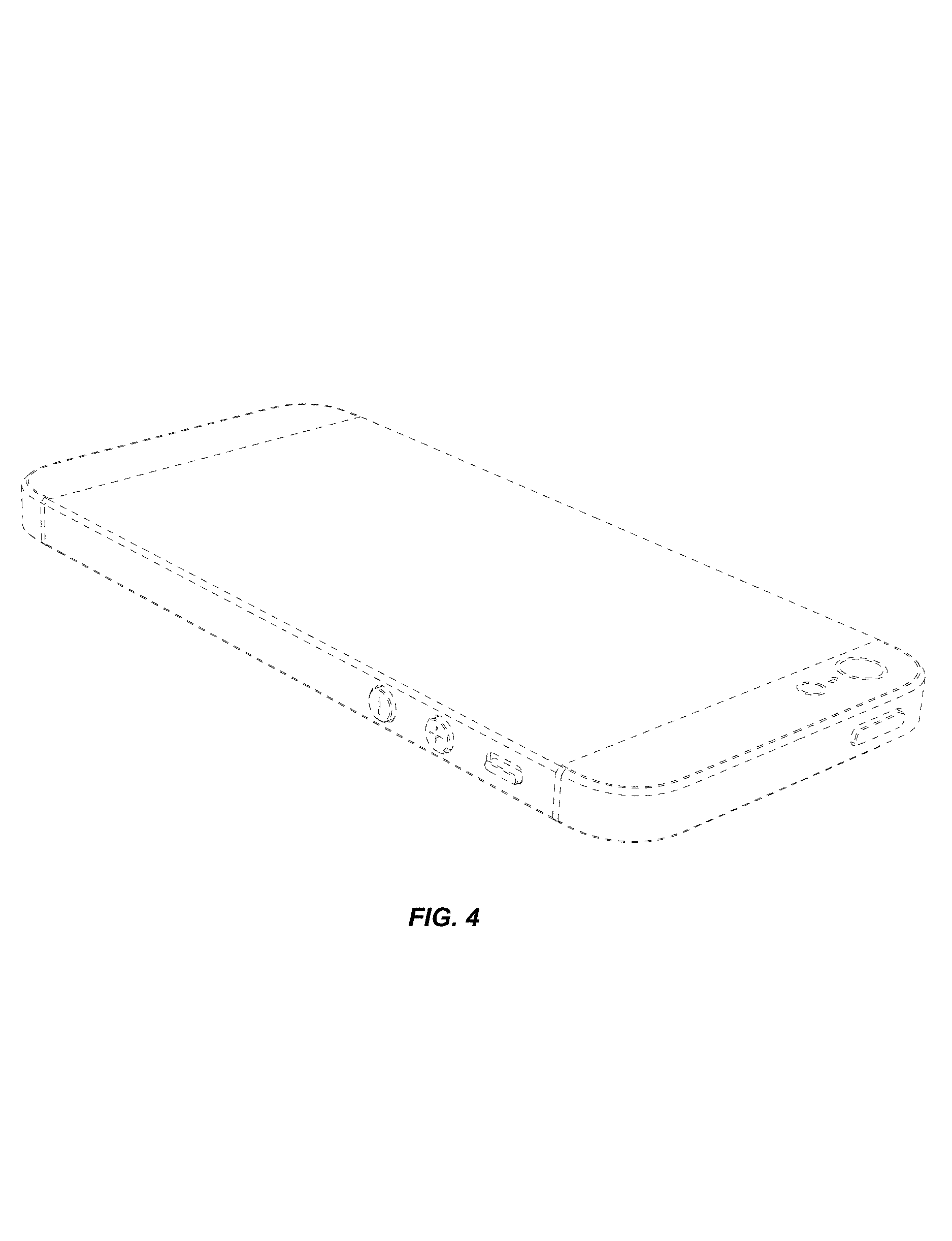
FIG. 4 is a top rear perspective view thereof;
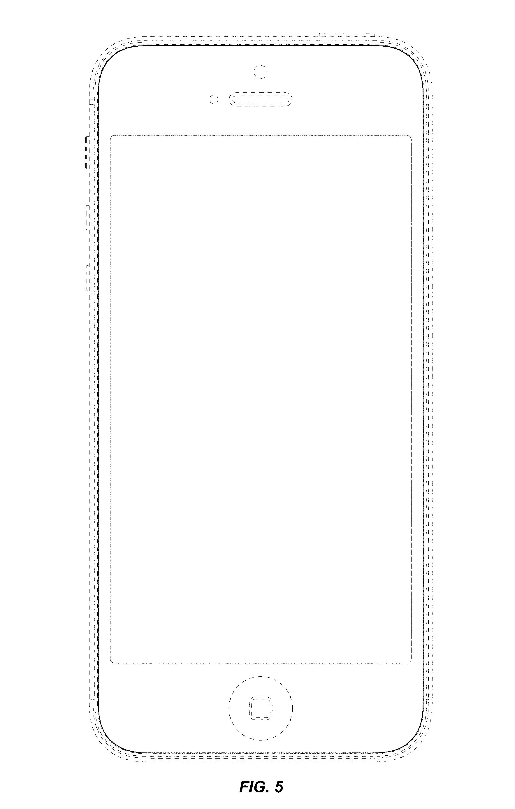
FIG. 5 is a front view thereof;
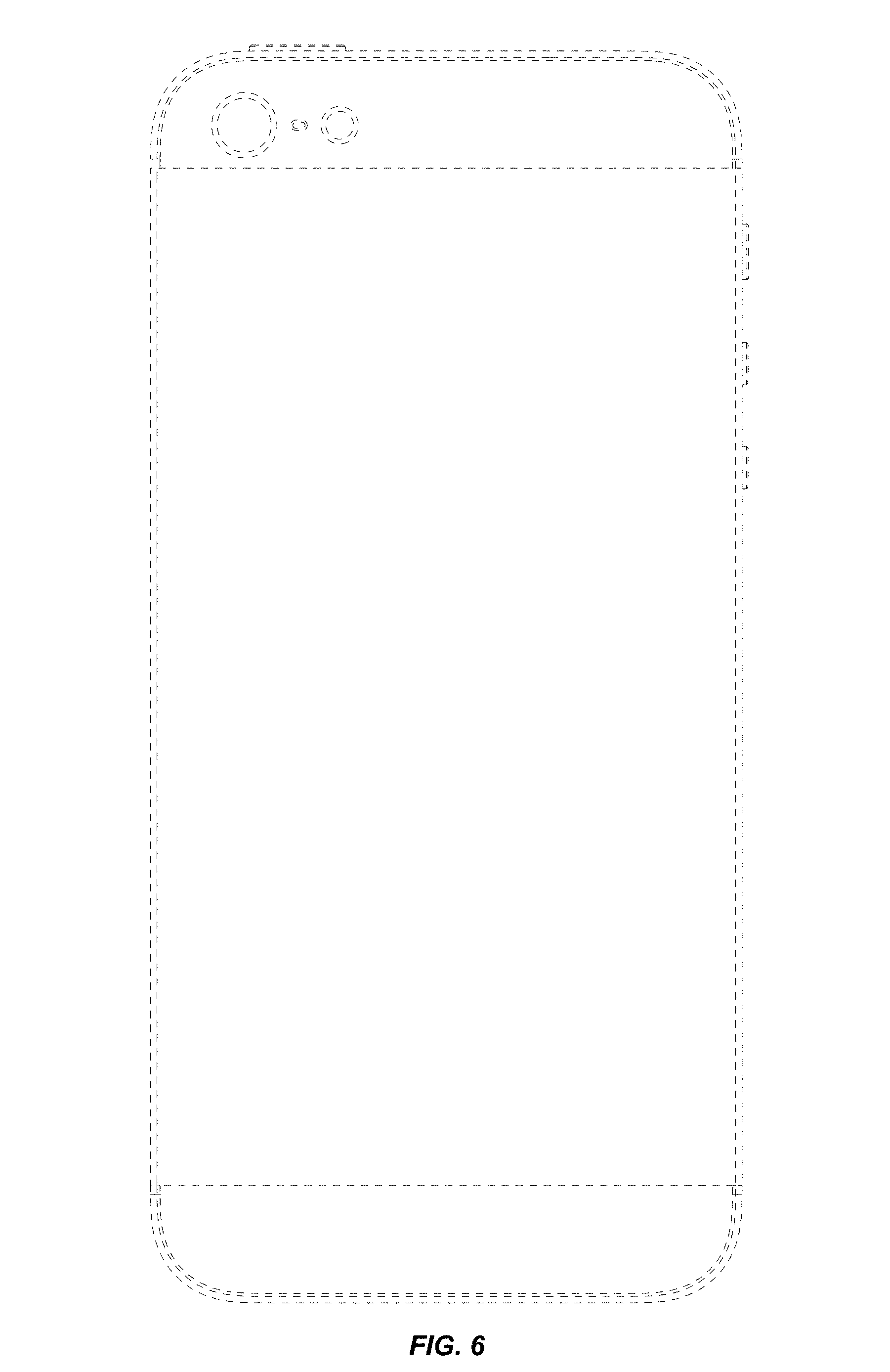
FIG. 6 is a rear view thereof;
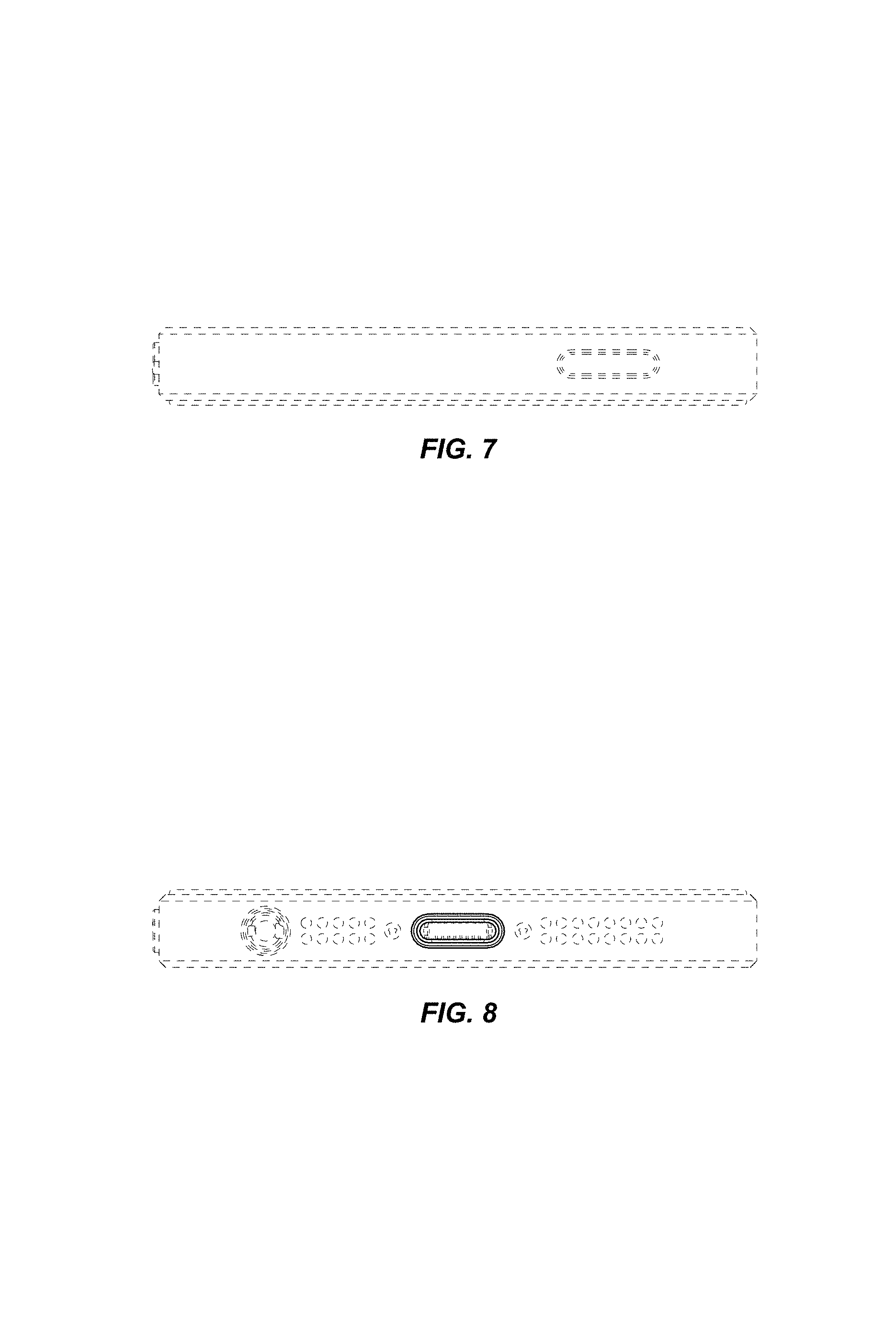
FIG. 7 is a top view thereof;
FIG. 8 is a bottom view thereof;
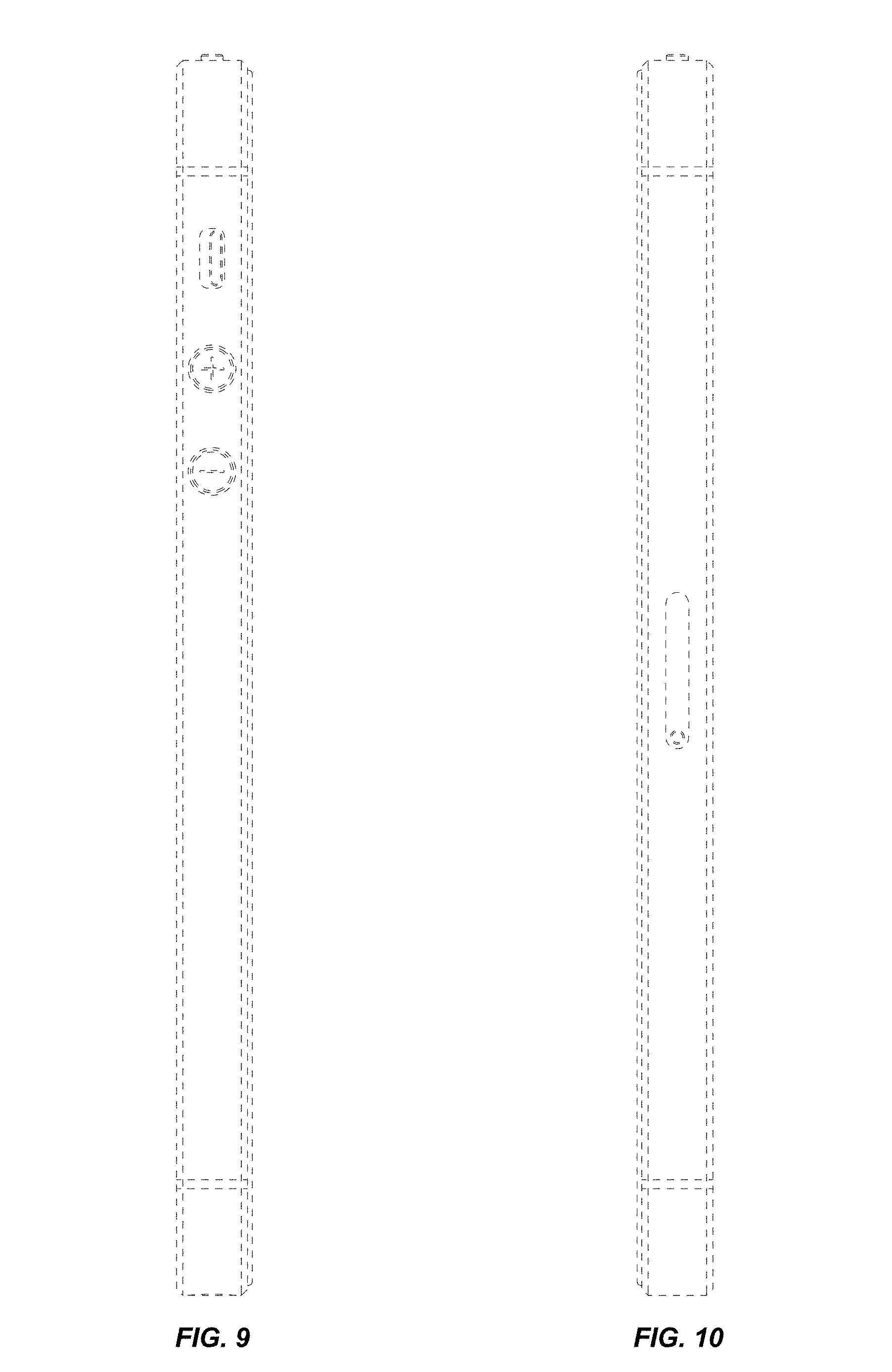
FIG. 9 is a left side view thereof; and,
FIG. 10 is a right side view thereof.
The broken lines in the figures show portions of the electronic device that form no part of the claimed design.
* * * * *
D00000
D00001
D00002
D00003
D00004
D00005
D00006
D00007
D00008
XML
uspto.report is an independent third-party trademark research tool that is not affiliated, endorsed, or sponsored by the United States Patent and Trademark Office (USPTO) or any other governmental organization. The information provided by uspto.report is based on publicly available data at the time of writing and is intended for informational purposes only.
While we strive to provide accurate and up-to-date information, we do not guarantee the accuracy, completeness, reliability, or suitability of the information displayed on this site. The use of this site is at your own risk. Any reliance you place on such information is therefore strictly at your own risk.
All official trademark data, including owner information, should be verified by visiting the official USPTO website at www.uspto.gov. This site is not intended to replace professional legal advice and should not be used as a substitute for consulting with a legal professional who is knowledgeable about trademark law.