Hospital cart
Brooks , et al. Oc
U.S. patent number D863,559 [Application Number D/623,518] was granted by the patent office on 2019-10-15 for hospital cart. The grantee listed for this patent is Capsa Solutions, LLC. Invention is credited to Richard Jason Brooks, Joseph R. D'Amico, Derek J. Nash, Stephen C. Torbett.


| United States Patent | D863,559 |
| Brooks , et al. | October 15, 2019 |
| **Please see images for: ( Certificate of Correction ) ** |
Hospital cart
Claims
CLAIM The ornamental design for a hospital cart, as shown.
| Inventors: | Brooks; Richard Jason (Huntersville, NC), D'Amico; Joseph R. (Fort Mill, SC), Torbett; Stephen C. (Lake Wylie, SC), Nash; Derek J. (Greer, SC) | ||||||||||
|---|---|---|---|---|---|---|---|---|---|---|---|
| Applicant: |
|
||||||||||
| Appl. No.: | D/623,518 | ||||||||||
| Filed: | October 25, 2017 |
Related U.S. Patent Documents
| Application Number | Filing Date | Patent Number | Issue Date | ||
|---|---|---|---|---|---|
| 13782841 | Mar 1, 2013 | ||||
| Current U.S. Class: | D24/185 |
| Current International Class: | 2402 |
| Field of Search: | ;D24/185,164,158,186,160,167 ;D34/14,17 ;D14/302 |
References Cited [Referenced By]
U.S. Patent Documents
| D375601 | November 1996 | Myers |
| D376459 | December 1996 | Myers |
| D389917 | January 1998 | Hornback et al. |
| 6480762 | November 2002 | Uchikubo et al. |
| D482172 | November 2003 | Johnson |
| D517768 | March 2006 | Arceta |
| D518267 | March 2006 | Arceta |
| 7155306 | December 2006 | Haitin et al. |
| D539794 | April 2007 | Rossini |
| D540002 | April 2007 | Perrier |
| D543000 | May 2007 | Perrier |
| D544962 | June 2007 | Diener |
| D548918 | August 2007 | Nussberger |
| D552324 | October 2007 | Perrier |
| 7594668 | September 2009 | Arceta et al. |
| 7621544 | November 2009 | Rossini |
| D606202 | December 2009 | Banryu |
| D626235 | October 2010 | Smith |
| D632797 | February 2011 | Ross |
| D648855 | November 2011 | Smith |
| D650142 | December 2011 | McRorie |
| D652521 | January 2012 | Ross |
| D652936 | January 2012 | Ross |
| 8109527 | February 2012 | Bustle et al. |
| D657470 | April 2012 | Schon |
| 8196939 | June 2012 | Bustle et al. |
| 8215650 | July 2012 | Arceta et al. |
| 8240684 | August 2012 | Ross et al. |
| D670062 | October 2012 | Sonnendorfer |
| D670063 | October 2012 | Sonnendorfer |
| 8286977 | October 2012 | Butler |
| D681303 | April 2013 | Sonnendorfer |
| D687147 | July 2013 | Yoshida |
| D696783 | December 2013 | Chung |
| 8651594 | February 2014 | Jones |
| D700706 | March 2014 | Molter |
| 8677911 | March 2014 | McRorie |
| D702842 | April 2014 | Hyde |
| 8714569 | May 2014 | Lu et al. |
| D708341 | July 2014 | Ikegame |
| D712540 | September 2014 | Hansen |
| D722696 | February 2015 | Blomquist |
| D730011 | May 2015 | McRorie |
| D760390 | June 2016 | Blomquist |
| D764669 | August 2016 | Birath |
| D769448 | October 2016 | Adams |
| D776279 | January 2017 | Newman |
| D777927 | January 2017 | Choudhary |
| D807510 | January 2018 | Newman |
| D824521 | July 2018 | Adams |
| D825763 | August 2018 | Lim |
| D827139 | August 2018 | Henderson |
| D836781 | December 2018 | Meurer |
| 2004/0179332 | September 2004 | Smith |
| 2004/0186357 | September 2004 | Soderberg |
| 2004/0262867 | December 2004 | Arceta et al. |
| 2005/0065817 | March 2005 | Mihai et al. |
| 2005/0159784 | July 2005 | Arceta |
| 2005/0245708 | November 2005 | Tada et al. |
| 2006/0142657 | June 2006 | Qauid |
| 2008/0146922 | June 2008 | Steins |
| 2008/0252045 | October 2008 | Rossini et al. |
| 2009/0015116 | January 2009 | Arceta et al. |
| 2009/0212670 | August 2009 | Bustle |
| 2009/0319079 | December 2009 | Arceta et al. |
| 2010/0213679 | August 2010 | Smith et al. |
| 2011/0247903 | October 2011 | Boukhny |
| 2011/0272902 | November 2011 | Arceta et al. |
| 2012/0274196 | January 2012 | Arceta et al. |
| 2012/0126503 | May 2012 | Butler et al. |
| 2012/0203377 | August 2012 | Paydar |
| 2012/0212116 | August 2012 | McRorie et al. |
| 2012/0236496 | September 2012 | McRorie |
| 2013/0085615 | April 2013 | Barker |
| 2013/0194072 | August 2013 | Kim et al. |
| 2013/0200579 | August 2013 | Abernethy et al. |
| 2013/0300075 | November 2013 | Arceta et al. |
| 2013/0307237 | November 2013 | Chen |
| 2014/0084558 | March 2014 | Ergun et al. |
| 2014/0218282 | August 2014 | Hung |
| 2014/0265193 | September 2014 | Stark |
| 2004/076604 | Sep 2004 | WO | |||
Attorney, Agent or Firm: Standley Law Group LLP Smith; Adam J. Standley; Jeffrey S.
Description
FIG. 1 is a front perspective view of the hospital cart;
FIG. 2 is a front elevation view of the FIG. 1 device;
FIG. 3 is a rear elevation view of the FIG. 1 device;
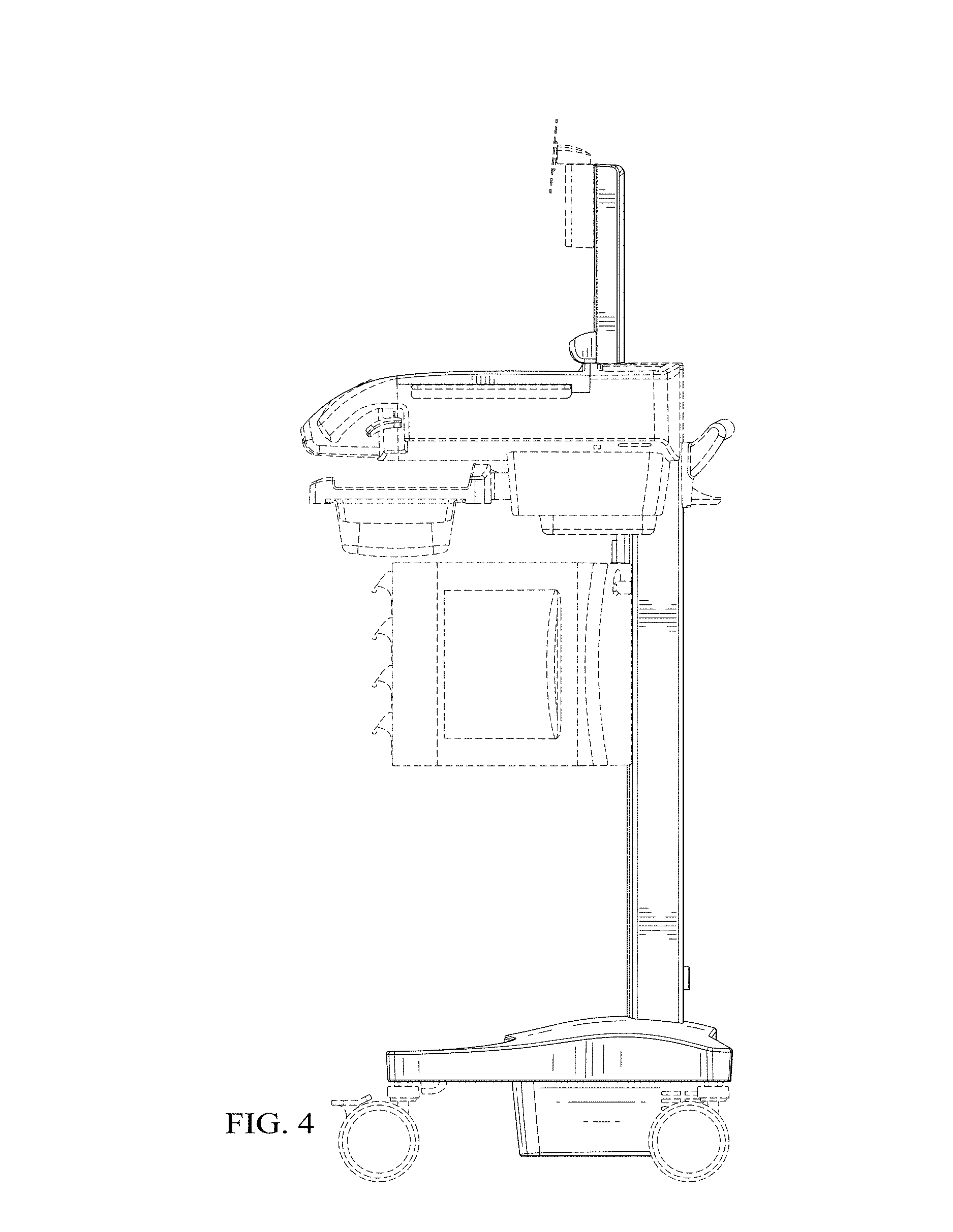
FIG. 4 is a right side elevation view of the FIG. 1 device;
FIG. 5 is a left side elevation view of the FIG. 1 device;
FIG. 6 is a top plan view of the FIG. 1 device;
FIG. 7 is a bottom plan view of the FIG. 1 device; and,
FIG. 8 is a rear perspective view of the FIG. 1 device.
In the drawings, the broken lines are for the purpose of illustrating environment only and form no part of the claimed design.
* * * * *
D00000
D00001
D00002
D00003
D00004
D00005
D00006
D00007
XML
uspto.report is an independent third-party trademark research tool that is not affiliated, endorsed, or sponsored by the United States Patent and Trademark Office (USPTO) or any other governmental organization. The information provided by uspto.report is based on publicly available data at the time of writing and is intended for informational purposes only.
While we strive to provide accurate and up-to-date information, we do not guarantee the accuracy, completeness, reliability, or suitability of the information displayed on this site. The use of this site is at your own risk. Any reliance you place on such information is therefore strictly at your own risk.
All official trademark data, including owner information, should be verified by visiting the official USPTO website at www.uspto.gov. This site is not intended to replace professional legal advice and should not be used as a substitute for consulting with a legal professional who is knowledgeable about trademark law.