Hydronic zone controller
Erbacher , et al. O
U.S. patent number D862,255 [Application Number D/631,592] was granted by the patent office on 2019-10-08 for hydronic zone controller. This patent grant is currently assigned to Ademco Inc.. The grantee listed for this patent is Ademco Inc.. Invention is credited to Nathan Carlson, Jonathan Erbacher, Travis Read, Rajat Shail, Cameron Vreeland.


View All Diagrams
| United States Patent | D862,255 |
| Erbacher , et al. | October 8, 2019 |
Hydronic zone controller
Claims
CLAIM The ornamental design for a hydronic zone controller, as shown and described.
| Inventors: | Erbacher; Jonathan (Minneapolis, MN), Read; Travis (Little Canada, MN), Shail; Rajat (Stevensville, MI), Vreeland; Cameron (Mound, MN), Carlson; Nathan (Maple Grove, MN) | ||||||||||
|---|---|---|---|---|---|---|---|---|---|---|---|
| Applicant: |
|
||||||||||
| Assignee: | Ademco Inc. (Golden Valley,
MN) |
||||||||||
| Appl. No.: | D/631,592 | ||||||||||
| Filed: | December 29, 2017 |
| Current U.S. Class: | D10/49; D13/162 |
| Current International Class: | 1004 |
| Field of Search: | ;D10/49,50 ;D13/162,162.1,177 |
References Cited [Referenced By]
U.S. Patent Documents
| D290694 | July 1987 | Shimizu et al. |
| D304929 | December 1989 | Bench et al. |
| D312612 | December 1990 | Seymour |
| D401909 | December 1998 | Richman et al. |
| D558684 | January 2008 | Dornauer et al. |
| D562261 | February 2008 | Takach et al. |
| D562262 | February 2008 | Takach et al. |
| D563325 | March 2008 | Takach et al. |
| D570791 | June 2008 | Takach et al. |
| D571734 | June 2008 | Takach et al. |
| D602445 | October 2009 | Liu |
| D678218 | March 2013 | Sheen |
| D680501 | April 2013 | Elliott et al. |
| D693311 | November 2013 | Biller et al. |
| D727857 | April 2015 | Acera et al. |
| D733591 | July 2015 | Golden |
| D769743 | October 2016 | Li |
| D772085 | November 2016 | Howe et al. |
| D792353 | July 2017 | Yoshida et al. |
| D792789 | July 2017 | Read |
| D804432 | December 2017 | Burkell et al. |
| 10096996 | October 2018 | Lin |
Attorney, Agent or Firm: Shumaker & Sieffert, P.A.
Description
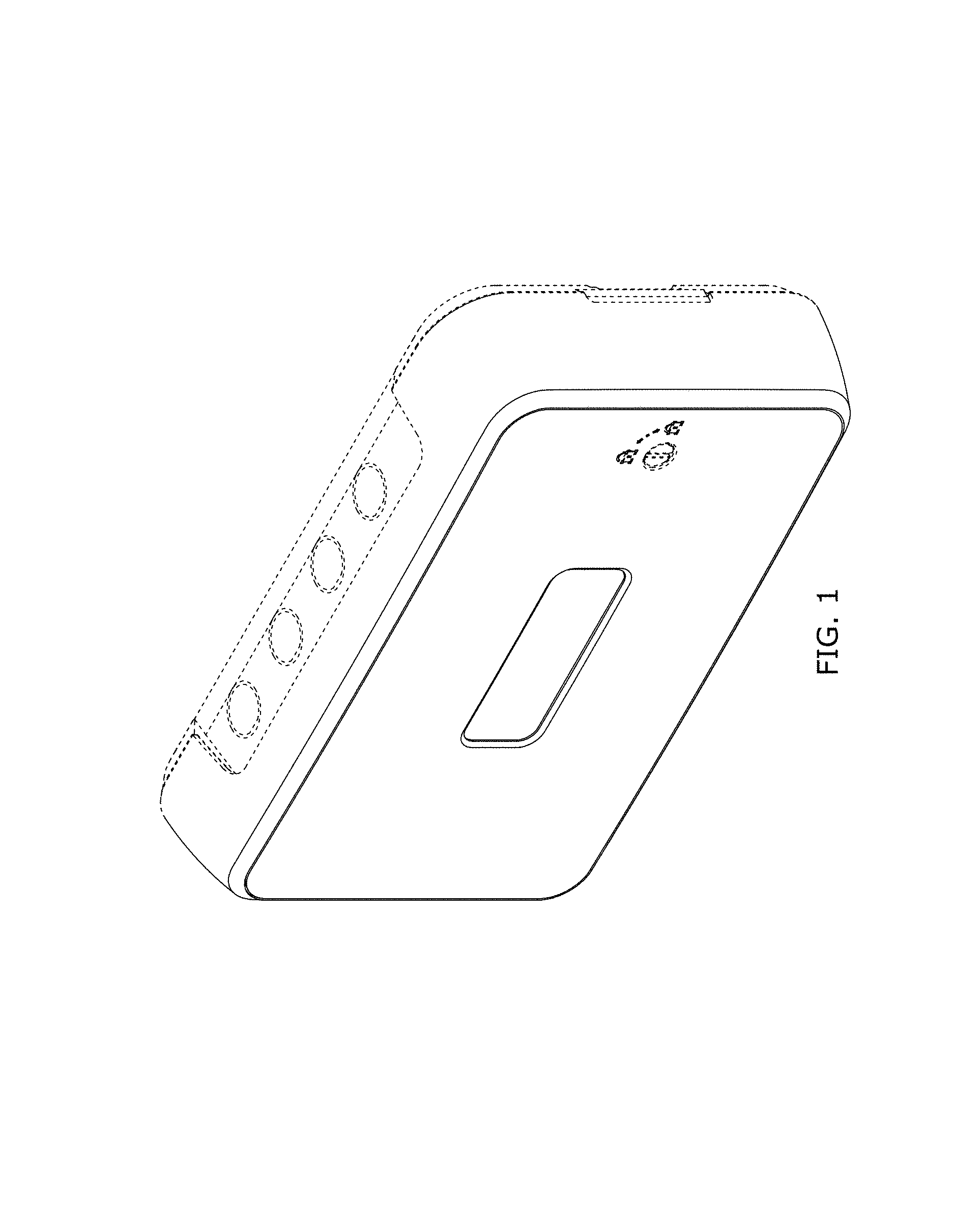
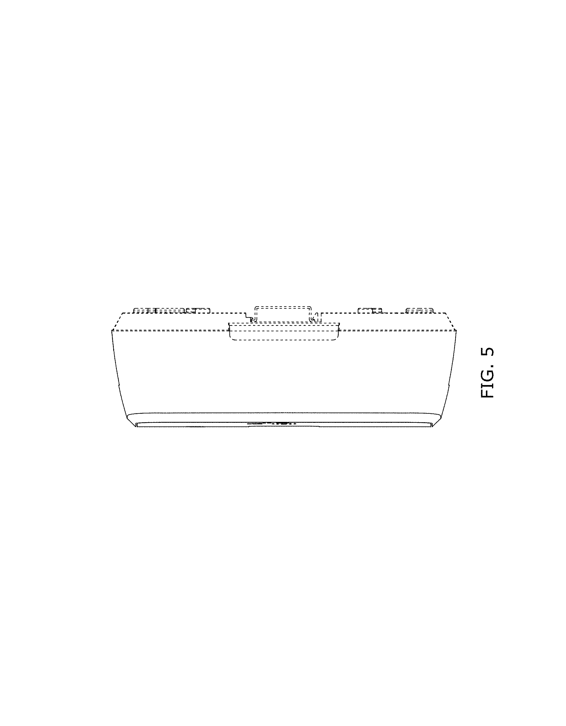
FIG. 1 is a perspective view of a first embodiment of the hydronic zone controller;
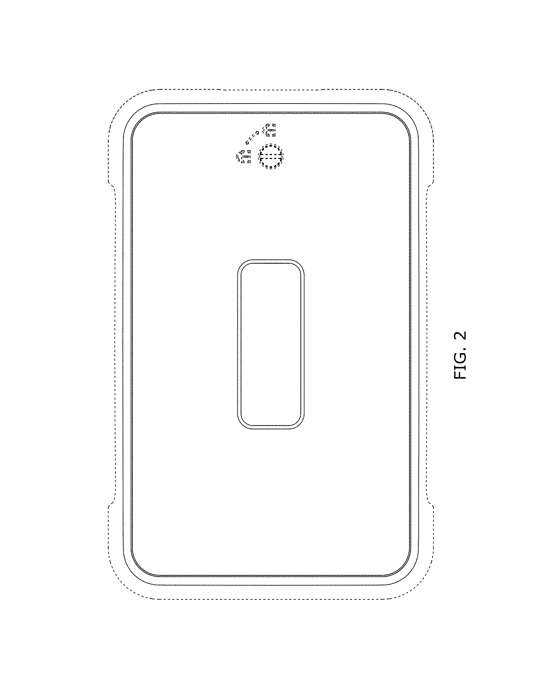
FIG. 2 is a front elevation view of the first embodiment of the hydronic zone controller of FIG. 1;
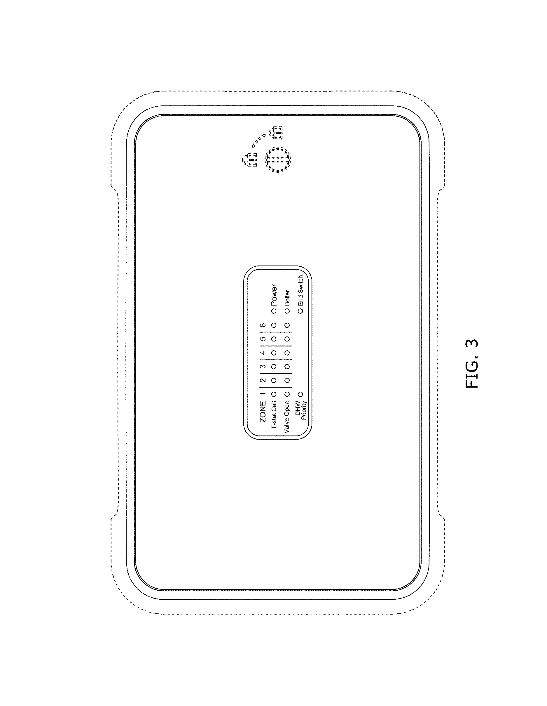
FIG. 3 is a front elevation view of the first embodiment of the hydronic zone controller of FIG. 1 with user interface elements added;
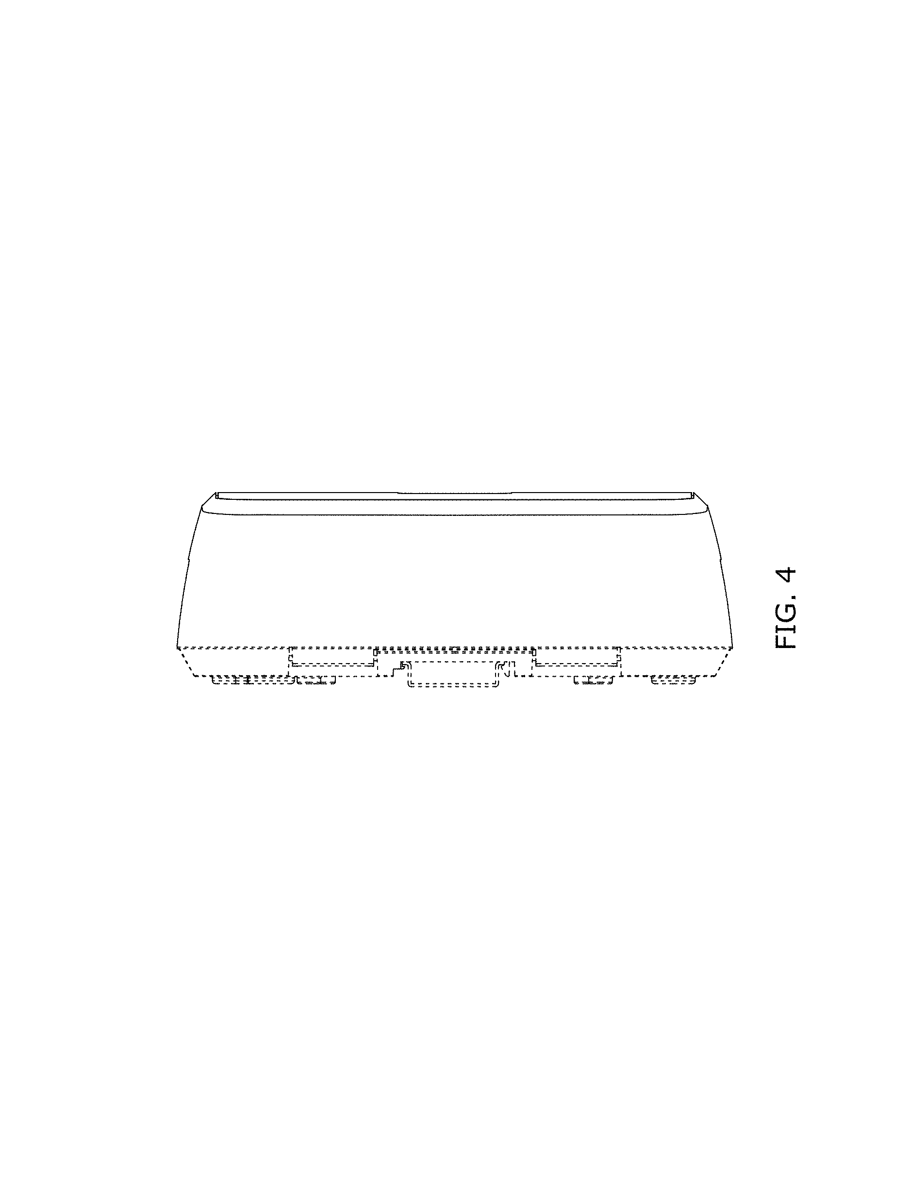
FIGS. 4-7 are left, right, top and bottom views, respectively, of the first embodiment of the hydronic zone controller of FIG. 1;
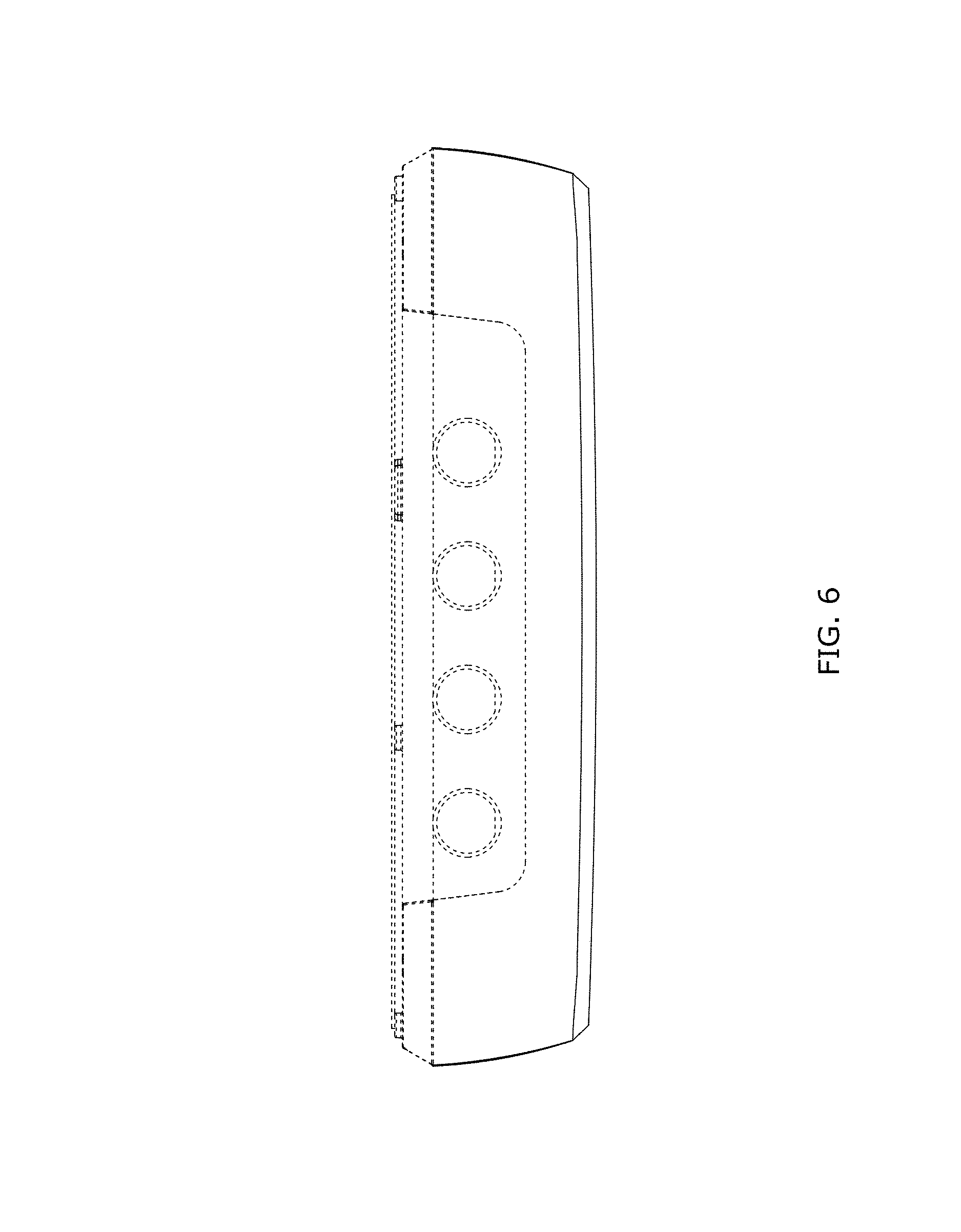
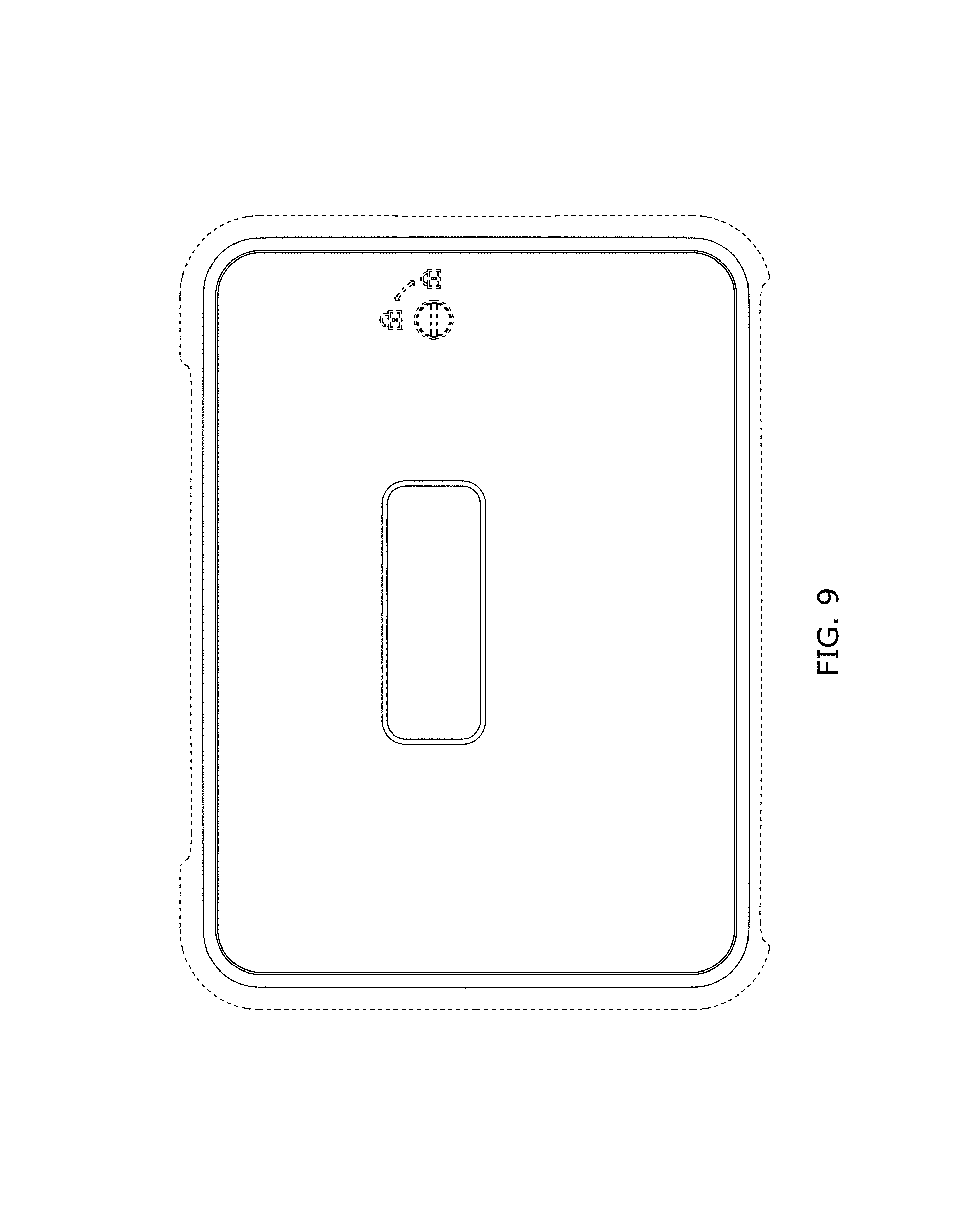
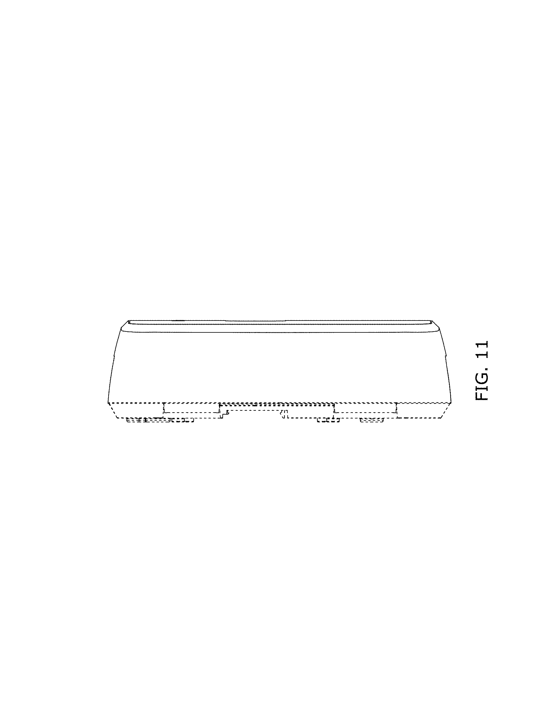
FIG. 8 is a perspective view of a second embodiment of the hydronic zone controller;
FIG. 9 is a front elevation view of the second embodiment of the hydronic zone controller of FIG. 8;
FIG. 10 is a front elevation view of the second embodiment of the hydronic zone controller of FIG. 8 with user interface elements added;
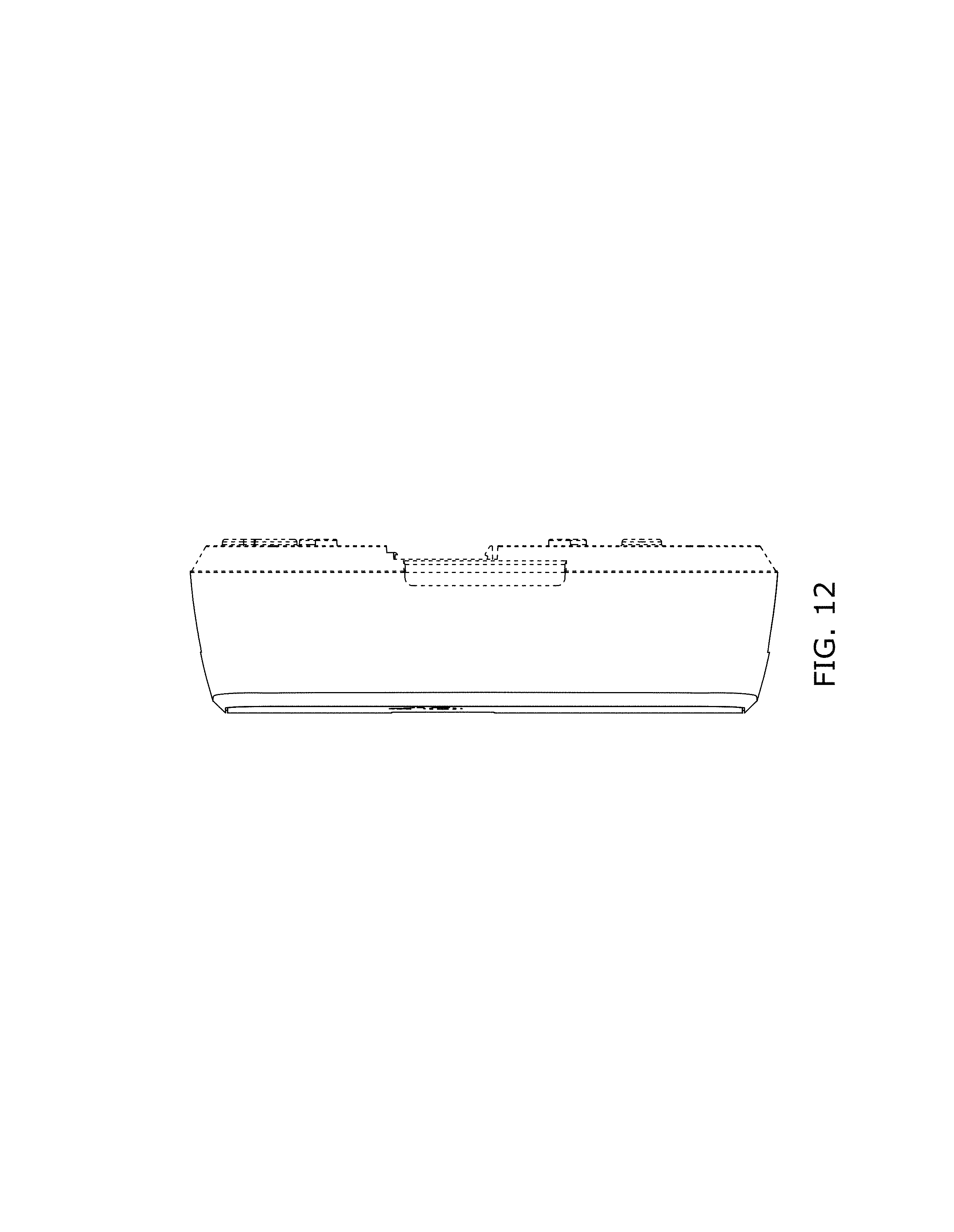
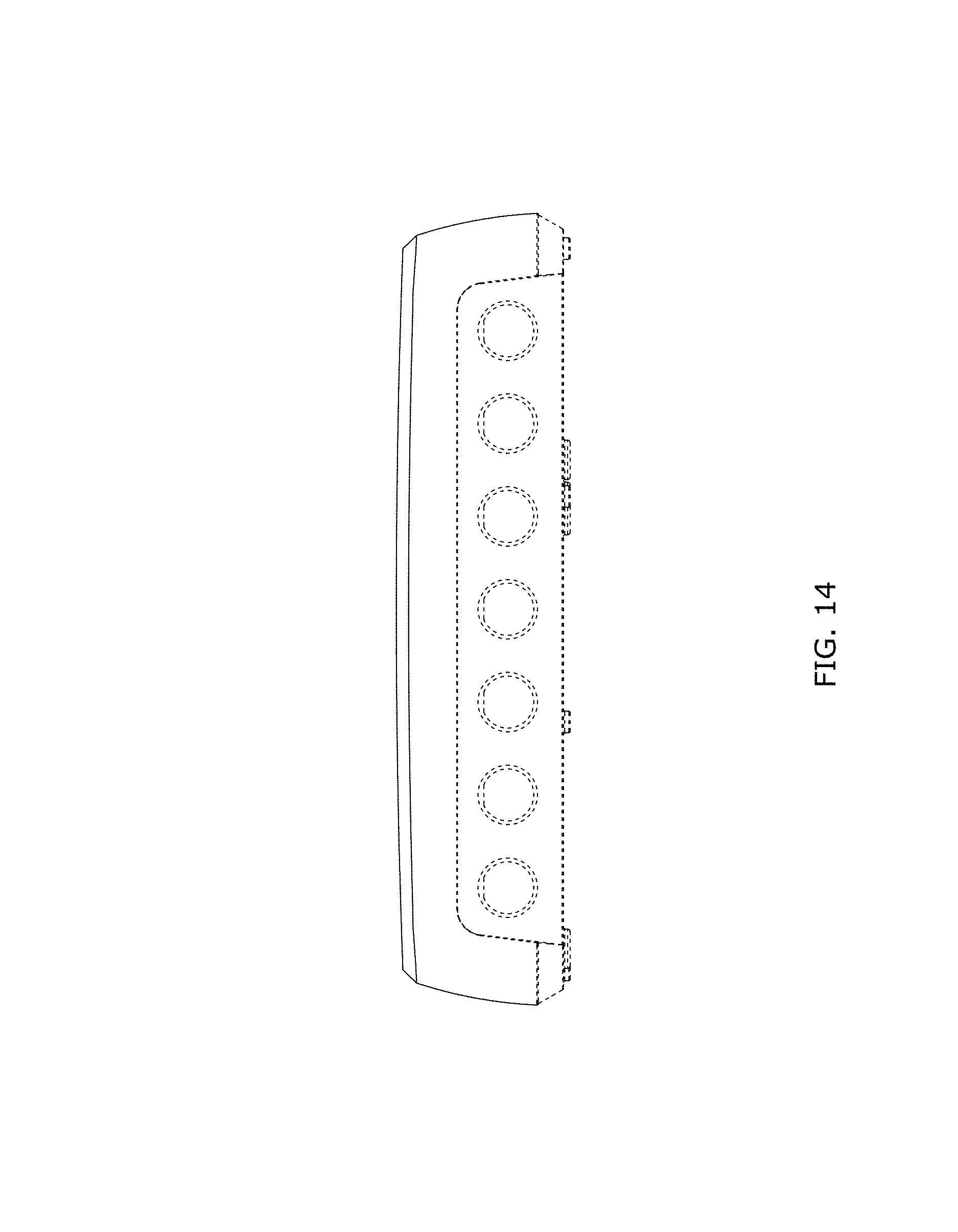
FIGS. 11-14 are left, right, top and bottom views, respectively, of the second embodiment of the hydronic zone controller of FIG. 8;
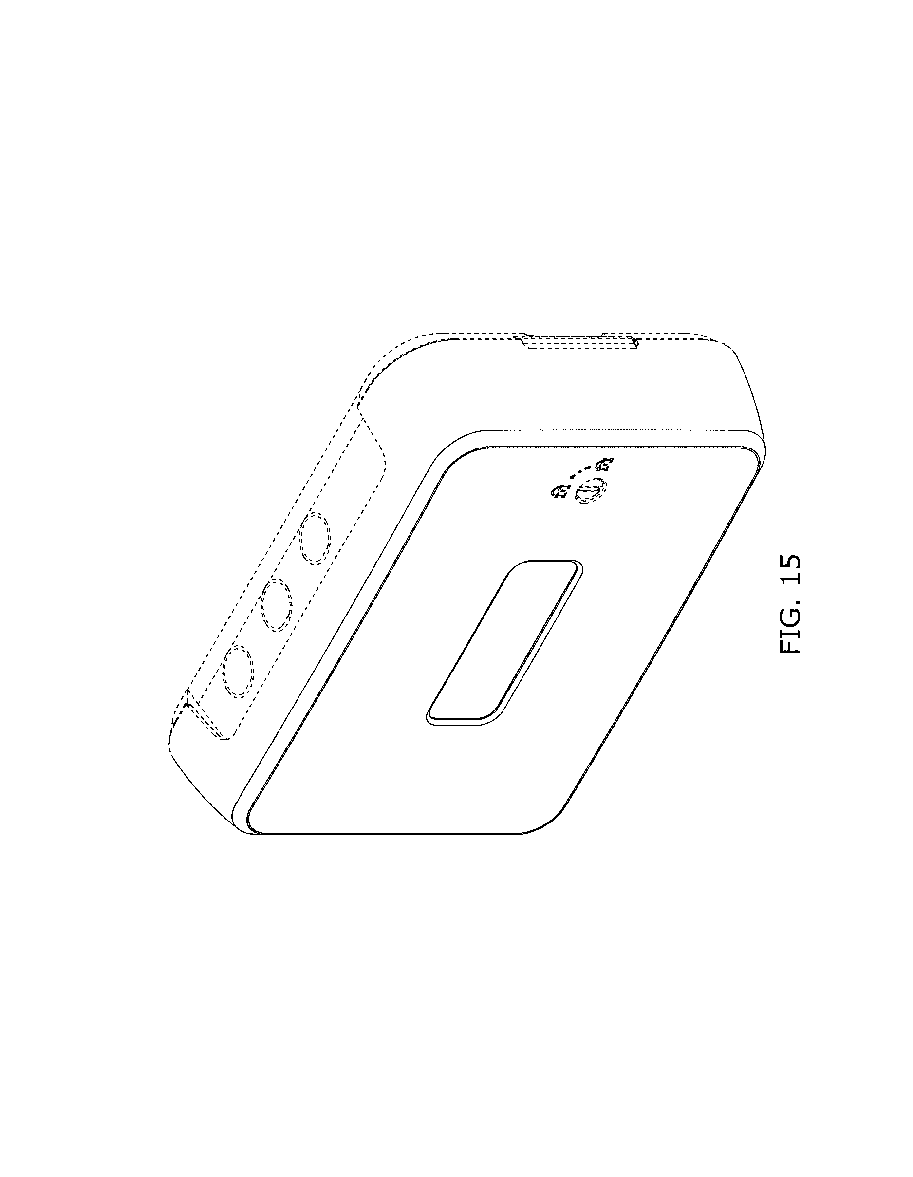
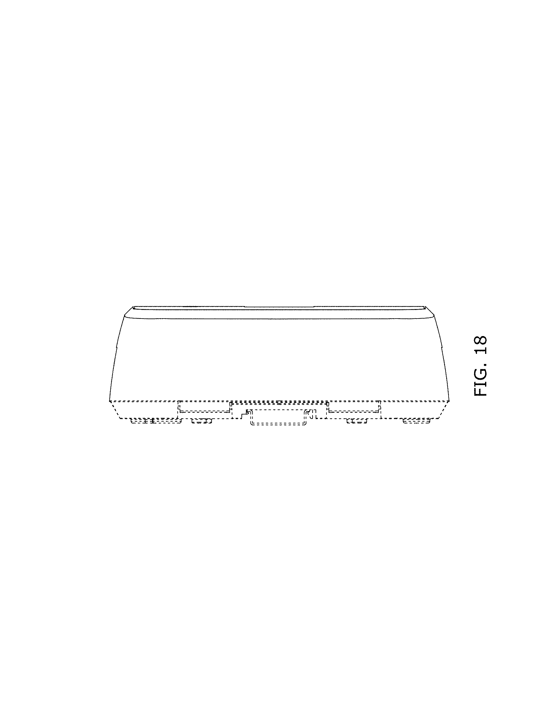
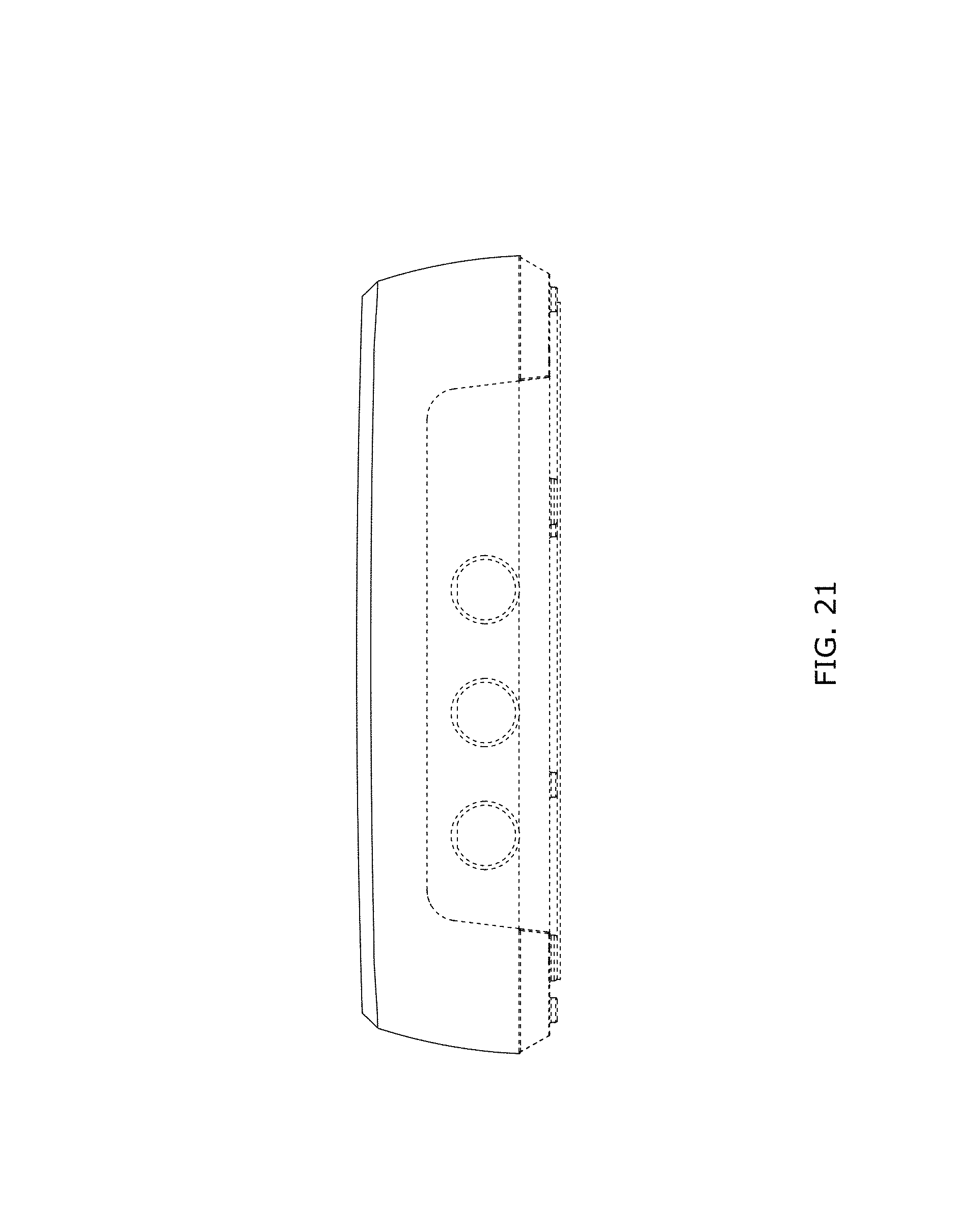
FIG. 15 is a perspective view of a third embodiment of the hydronic zone controller;
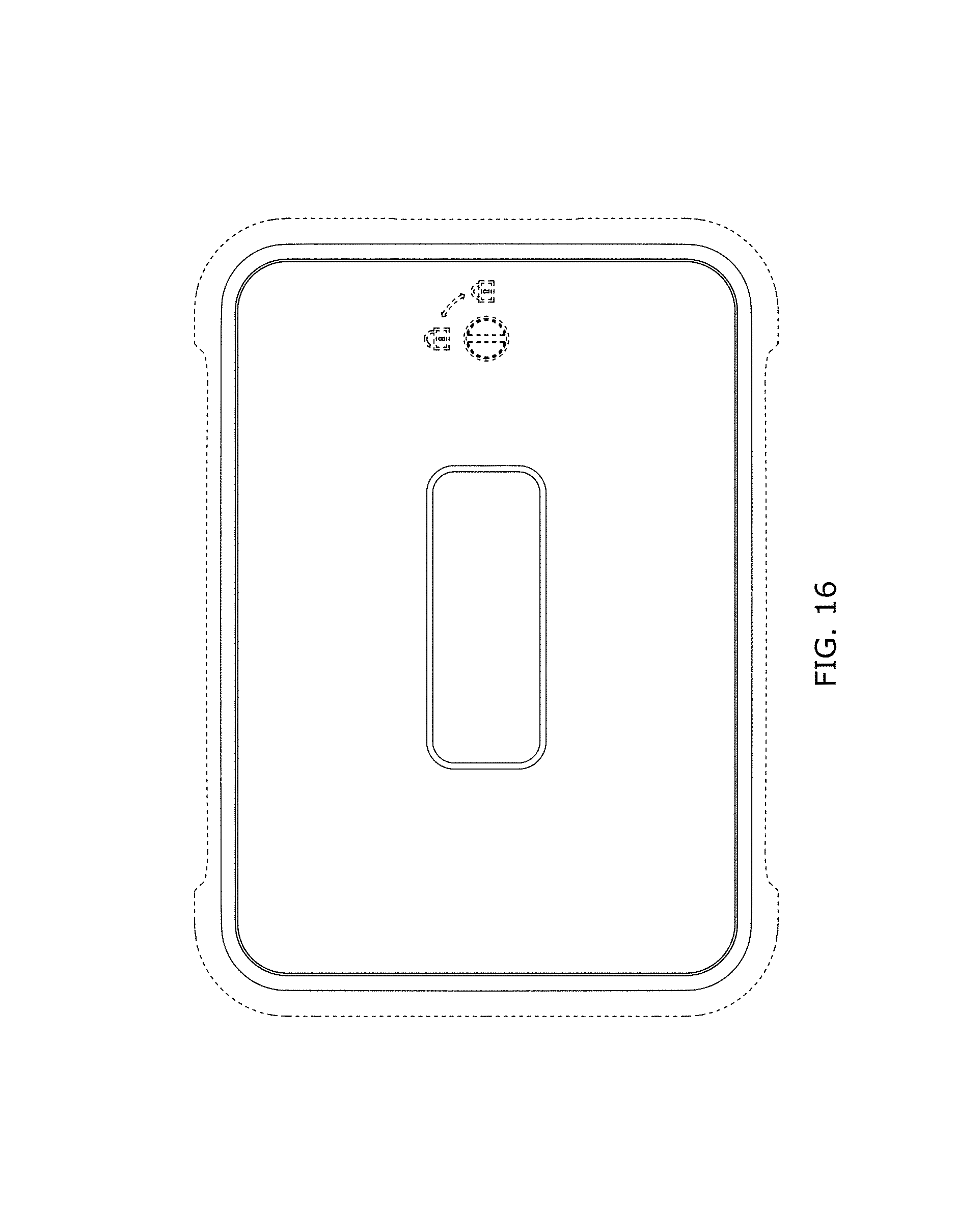
FIG. 16 is a front elevation view of the third embodiment of the hydronic zone controller of FIG. 15;
FIG. 17 is a front elevation view of the third embodiment of the hydronic zone controller of FIG. 15 with user interface elements added; and,
FIGS. 18-21 are left, right, top and bottom views, respectively, of the third embodiment of the hydronic zone controller of FIG. 15.
The portions illustrated in broken lines on the figures are for illustrative purposes only and form no part of the claimed design.
* * * * *
D00000
D00001
D00002
D00003
D00004
D00005
D00006
D00007
D00008
D00009
D00010
D00011
D00012
D00013

D00014
D00015
D00016
D00017

D00018
D00019

D00020

D00021
XML
uspto.report is an independent third-party trademark research tool that is not affiliated, endorsed, or sponsored by the United States Patent and Trademark Office (USPTO) or any other governmental organization. The information provided by uspto.report is based on publicly available data at the time of writing and is intended for informational purposes only.
While we strive to provide accurate and up-to-date information, we do not guarantee the accuracy, completeness, reliability, or suitability of the information displayed on this site. The use of this site is at your own risk. Any reliance you place on such information is therefore strictly at your own risk.
All official trademark data, including owner information, should be verified by visiting the official USPTO website at www.uspto.gov. This site is not intended to replace professional legal advice and should not be used as a substitute for consulting with a legal professional who is knowledgeable about trademark law.