Wireless charger
Choi , et al. O
U.S. patent number D861,600 [Application Number D/640,606] was granted by the patent office on 2019-10-01 for wireless charger. This patent grant is currently assigned to SAMSUNG ELECTRONICS CO., LTD.. The grantee listed for this patent is Samsung Electronics Co., Ltd.. Invention is credited to Jonghyuk Bae, Eunha Choi, Minki Ham, Namkyu Kim.


| United States Patent | D861,600 |
| Choi , et al. | October 1, 2019 |
Wireless charger
Claims
CLAIM The ornamental design for a wireless charger, as shown and described.
| Inventors: | Choi; Eunha (Seoul, KR), Bae; Jonghyuk (Seoul, KR), Ham; Minki (Seoul, KR), Kim; Namkyu (Seoul, KR) | ||||||||||
|---|---|---|---|---|---|---|---|---|---|---|---|
| Applicant: |
|
||||||||||
| Assignee: | SAMSUNG ELECTRONICS CO., LTD.
(Suwon-si, KR) |
||||||||||
| Appl. No.: | D/640,606 | ||||||||||
| Filed: | March 15, 2018 |
Foreign Application Priority Data
| Dec 21, 2017 [KR] | 30-2017-0060832 | |||
| Current U.S. Class: | D13/108; D14/253 |
| Current International Class: | 1302 |
| Field of Search: | ;D13/107-108,103,105,110,119,137.2 ;D14/434,447,253,224,217,238.1,251,240,149,358,348,356 |
References Cited [Referenced By]
U.S. Patent Documents
| D594404 | June 2009 | Kuo |
| D628153 | November 2010 | Fujii |
| D628203 | November 2010 | Noble |
| D654921 | February 2012 | Malsan |
| D659696 | May 2012 | Lanza |
| D662939 | July 2012 | Akana |
| D666204 | August 2012 | Han |
| D736210 | August 2015 | Paradise |
| D789295 | June 2017 | Nuk |
| D797042 | September 2017 | Miller |
| D797667 | September 2017 | Park |
| D797668 | September 2017 | Park |
| D841577 | February 2019 | Kim |
| D841578 | February 2019 | Kim |
| D845306 | April 2019 | Lee |
| D851036 | June 2019 | Saangloef |
| D851587 | June 2019 | Schmidt |
| 2009/0102419 | April 2009 | Gwon |
| 2015/0188339 | July 2015 | Green |
| 304313873 | Oct 2017 | CN | |||
| 304407353 | Dec 2017 | CN | |||
Other References
|
Devin Balentina, Samsung Wireless Adaptive Fast CHargin Stand EP-NG930 Review, Dec. 6, 2016, GadgetNutz, http://www.gadgetnutz.com/2016/12/06/the-samsung-wireless-adaptive-fast-c- harging-stand-ep-ng930-review/ (Year: 2016). cited by examiner . Andrew Martonik, Samsung Fast Charge Wireless Charging Stand review, May 4, 2016, androidcentral, https://www.androidcentral.com/samsung-fast-charge-wireless-charging-stan- d-review (Year: 2016). cited by examiner. |
Primary Examiner: Miller; Brett
Attorney, Agent or Firm: McAndrews Held & Malloy, Ltd.
Description
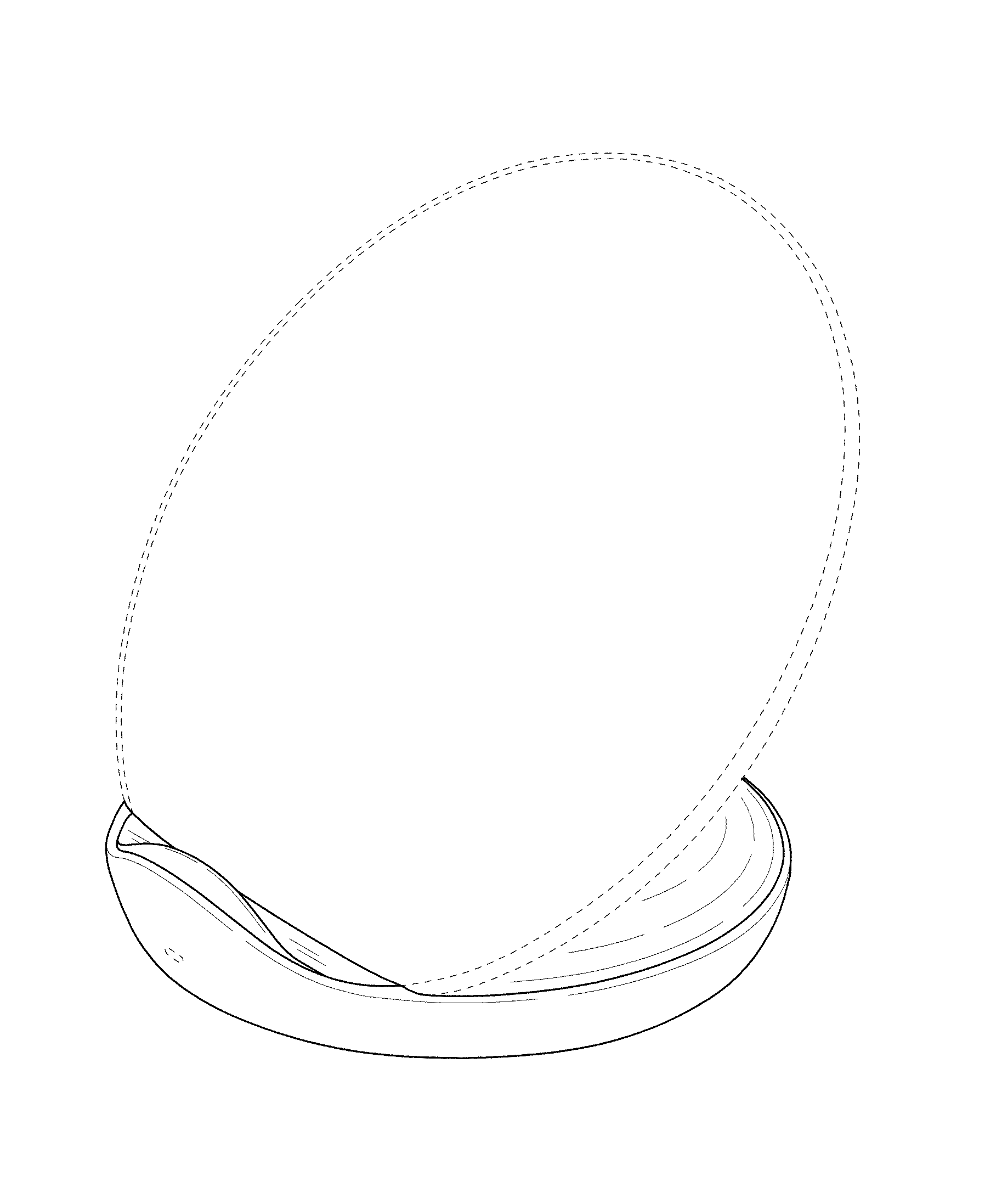
FIG. 1 is a front perspective view of a wireless charger showing our new design;
FIG. 2 is a front elevation view thereof;
FIG. 3 is a rear elevation view thereof;
FIG. 4 is a left side elevation view thereof;
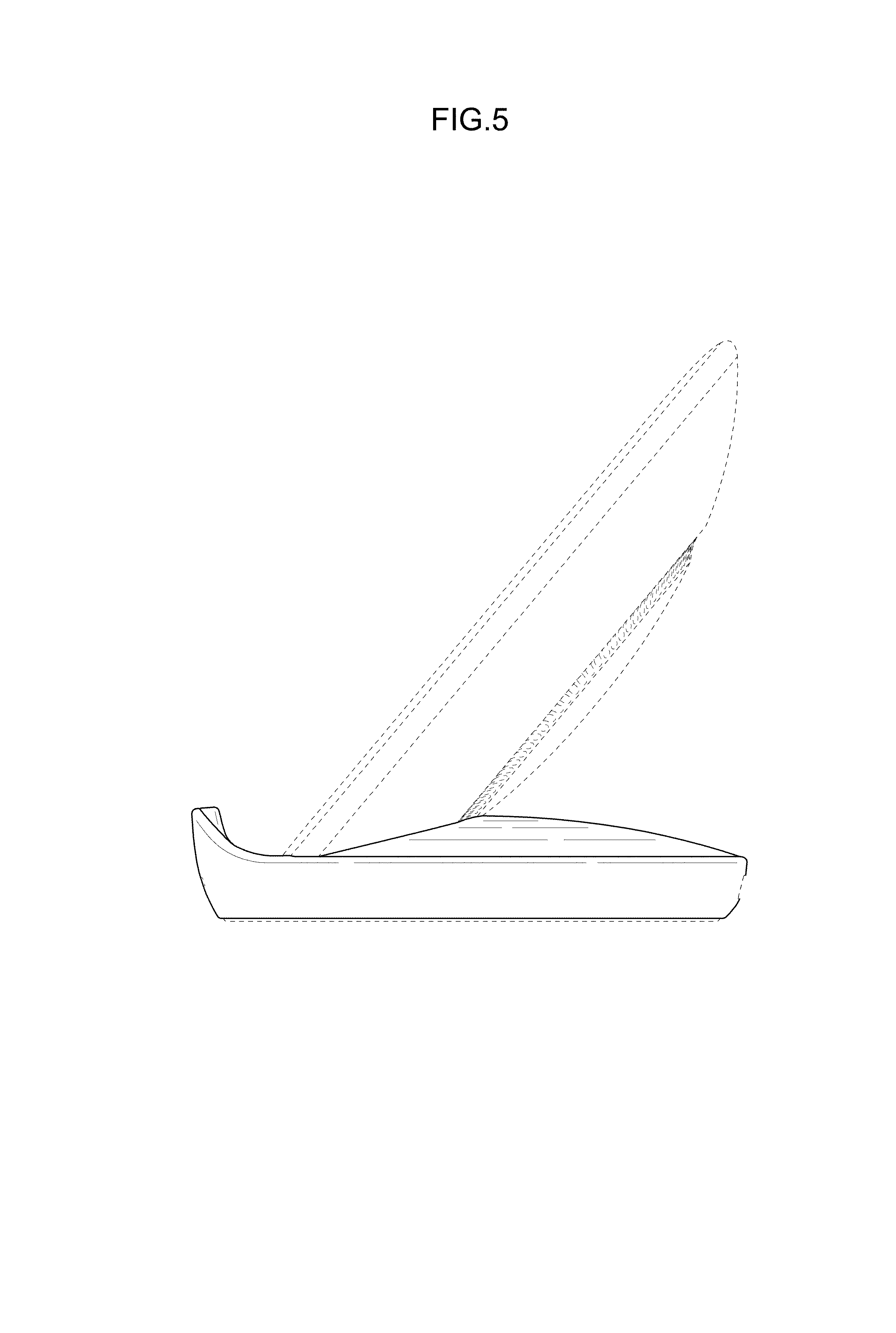
FIG. 5 is a right side elevation view thereof;
FIG. 6 is a top plan view thereof;
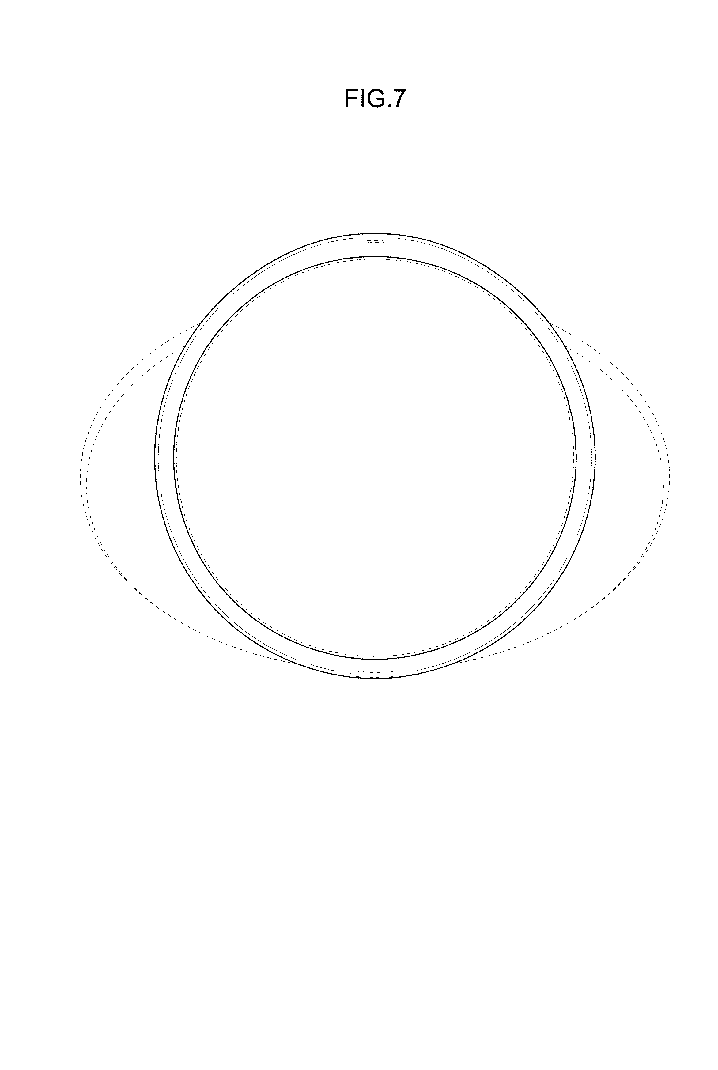
FIG. 7 is a bottom plan view thereof;
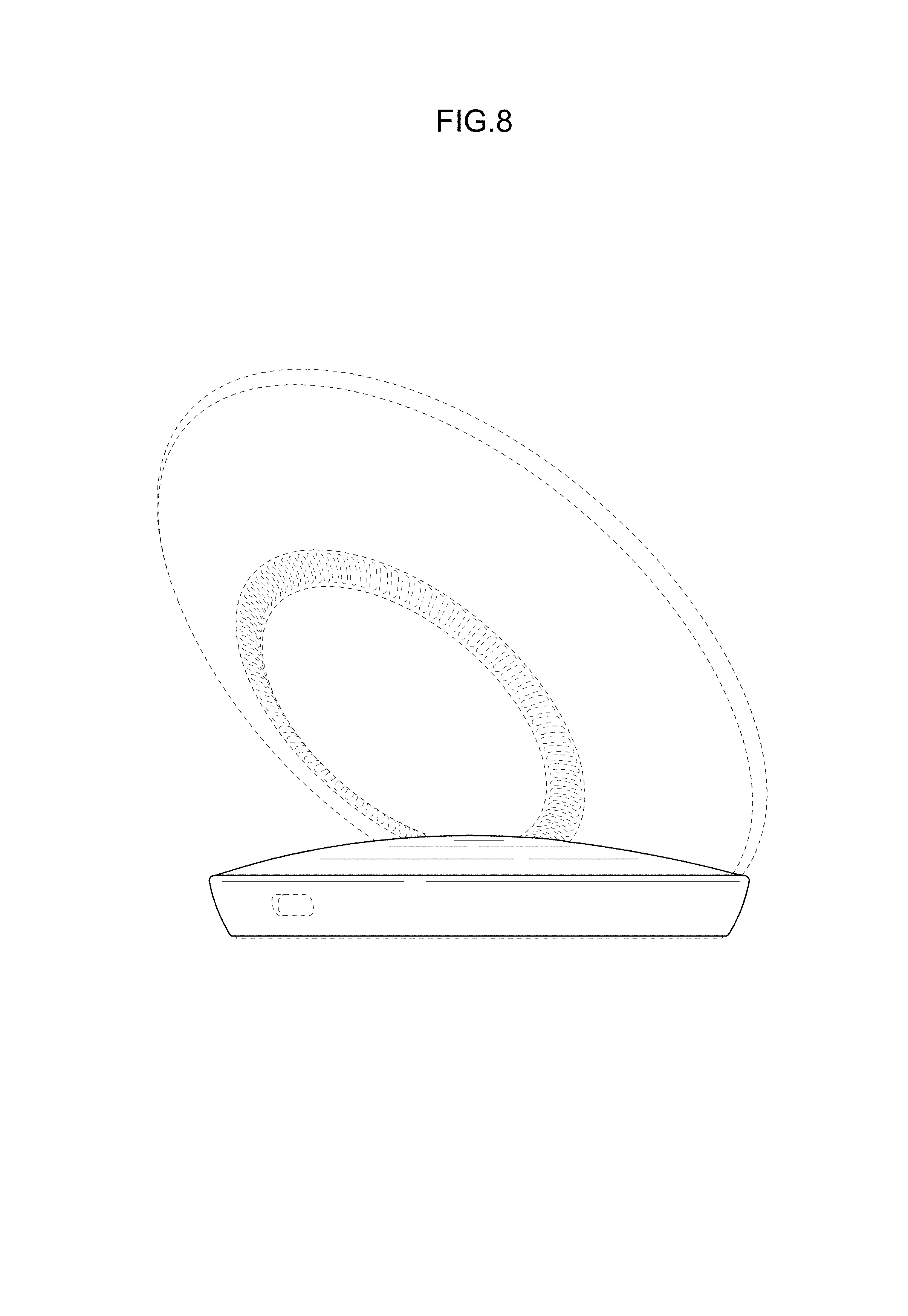
FIG. 8 is a rear perspective view thereof; and,
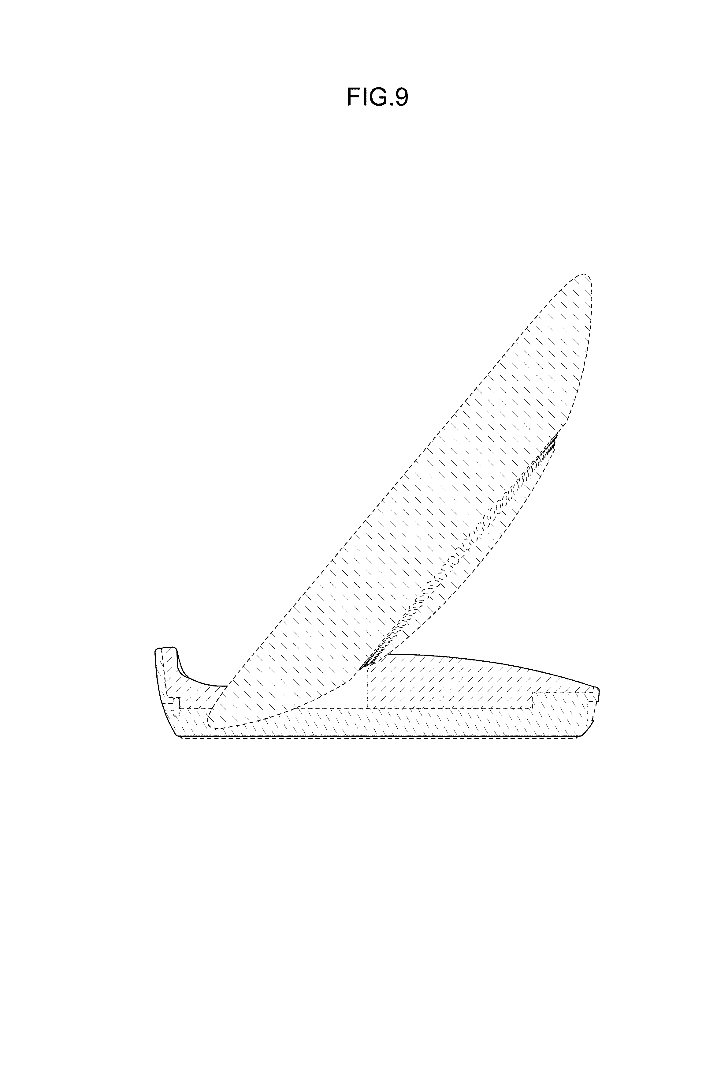
FIG. 9 is a cross-sectional view taken through line 9-9 of FIG. 2.
The dashed broken lines in the drawings illustrate portions of the wireless charger that form no part of the claimed design.
* * * * *
References
D00000
D00001
D00002
D00003
D00004
D00005
D00006
D00007
D00008
D00009
XML
uspto.report is an independent third-party trademark research tool that is not affiliated, endorsed, or sponsored by the United States Patent and Trademark Office (USPTO) or any other governmental organization. The information provided by uspto.report is based on publicly available data at the time of writing and is intended for informational purposes only.
While we strive to provide accurate and up-to-date information, we do not guarantee the accuracy, completeness, reliability, or suitability of the information displayed on this site. The use of this site is at your own risk. Any reliance you place on such information is therefore strictly at your own risk.
All official trademark data, including owner information, should be verified by visiting the official USPTO website at www.uspto.gov. This site is not intended to replace professional legal advice and should not be used as a substitute for consulting with a legal professional who is knowledgeable about trademark law.