Tie rod end
Baker , et al. O
U.S. patent number D861,545 [Application Number D/623,718] was granted by the patent office on 2019-10-01 for tie rod end. This patent grant is currently assigned to STEMCO PRODUCTS, INC.. The grantee listed for this patent is Stemco Products, Inc.. Invention is credited to James Allen Baker, Paul Dolan.


View All Diagrams
| United States Patent | D861,545 |
| Baker , et al. | October 1, 2019 |
Tie rod end
Claims
CLAIM The ornamental design for a tie rod end, as shown.
| Inventors: | Baker; James Allen (Vassar, MI), Dolan; Paul (Clio, MI) | ||||||||||
|---|---|---|---|---|---|---|---|---|---|---|---|
| Applicant: |
|
||||||||||
| Assignee: | STEMCO PRODUCTS, INC.
(Charlotte, NC) |
||||||||||
| Appl. No.: | D/623,718 | ||||||||||
| Filed: | October 26, 2017 |
| Current U.S. Class: | D12/160 |
| Current International Class: | 1216 |
| Field of Search: | ;D8/21,22,24,25,29,382-400 ;D12/159,160 |
References Cited [Referenced By]
U.S. Patent Documents
| D199149 | September 1964 | Greenlee |
| 3533315 | October 1970 | Maeda |
| D260353 | August 1981 | Redman |
| 4602534 | July 1986 | Moetteli |
| D296514 | July 1988 | Bygren |
| D340628 | October 1993 | Chow |
| D359429 | June 1995 | Williamson |
| D476867 | July 2003 | Walker |
| D525094 | July 2006 | Tuanmu |
| D566630 | April 2008 | Ortiz |
| D605008 | December 2009 | Robinson |
| D632533 | February 2011 | Cappuccio |
| D670984 | November 2012 | Albertson |
| D673827 | January 2013 | Cappuccio |
| D766142 | September 2016 | Renshaw |
| D773265 | December 2016 | Chen |
| D778698 | February 2017 | Huang |
| D820056 | June 2018 | Zhang |
| D821167 | June 2018 | James |
| D821931 | July 2018 | Winter |
| D824837 | August 2018 | Winter |
| D826134 | August 2018 | Winter |
| D839795 | February 2019 | Chirrey |
| 2003/0059250 | March 2003 | Moses |
| 2006/0012095 | January 2006 | Bjorkgard |
| 2013/0199332 | August 2013 | Powell |
| 2017/0225530 | August 2017 | Powell |
| 2018/0258983 | September 2018 | Reddehase |
| 302340627 | Mar 2013 | CN | |||
Other References
|
Qwiktie Tie Rod Assembly YouTube https://www.youtube.com/watch?v=ZFV0pc704Fw Jun. 27, 2017 (Year: 2017). cited by examiner. |
Primary Examiner: Was-Englehart; Leanne
Attorney, Agent or Firm: Perkins Coie LLP
Description
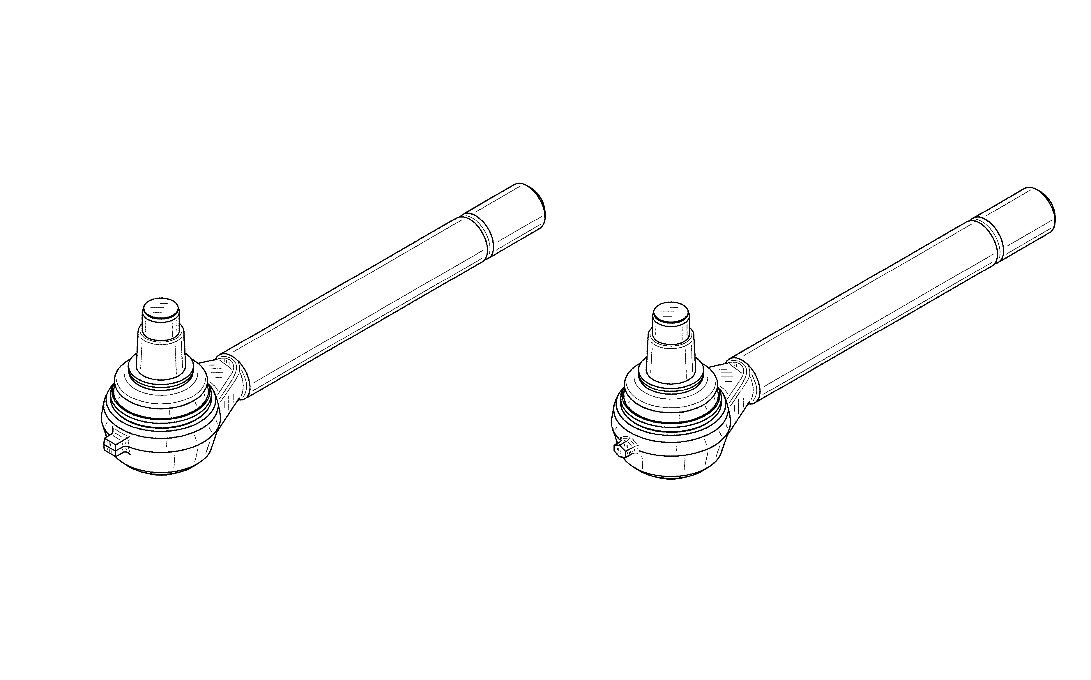
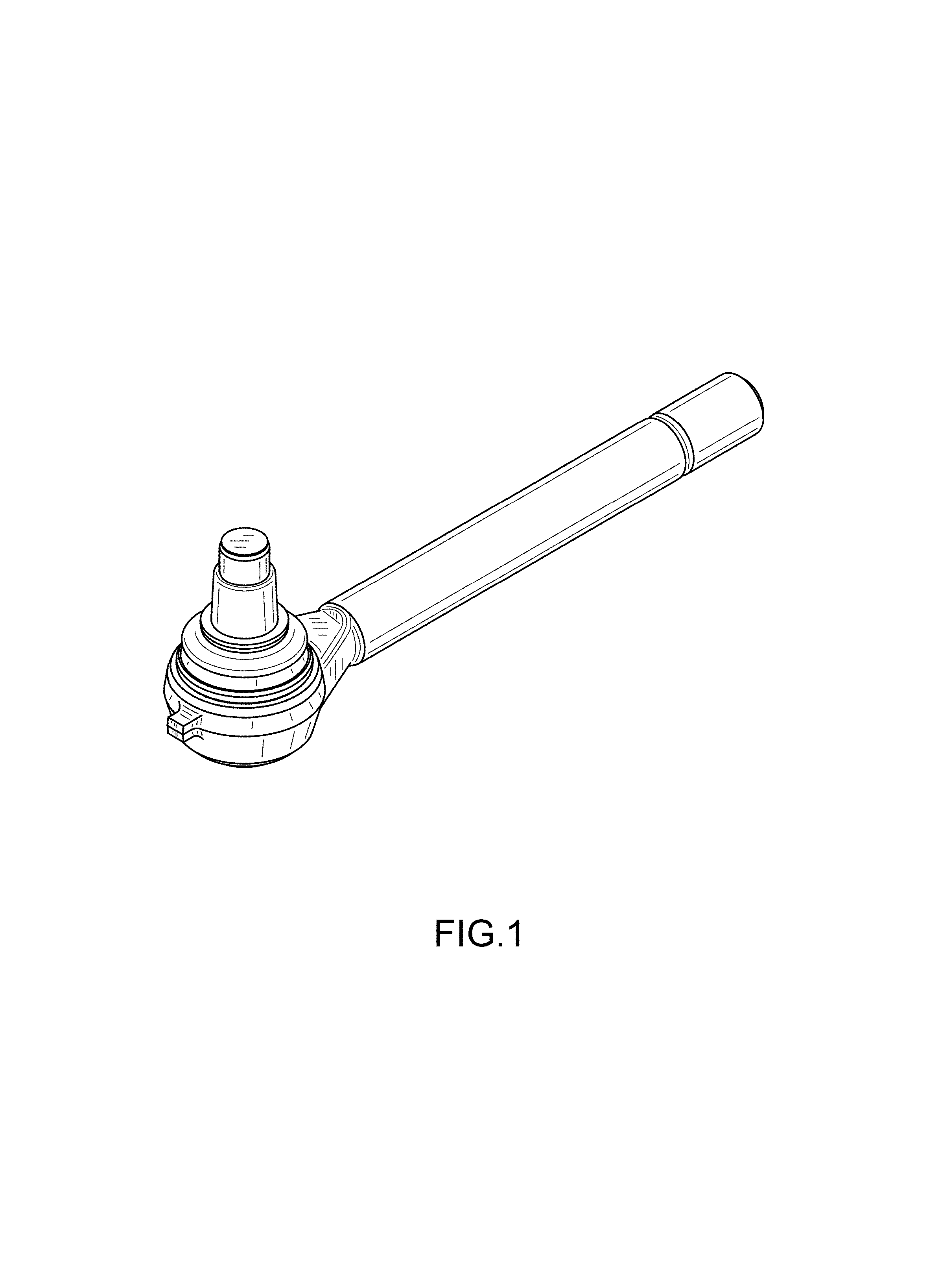
FIG. 1 is a perspective view of an embodiment of a tie rod end.
FIG. 2 is a front plan view thereof.
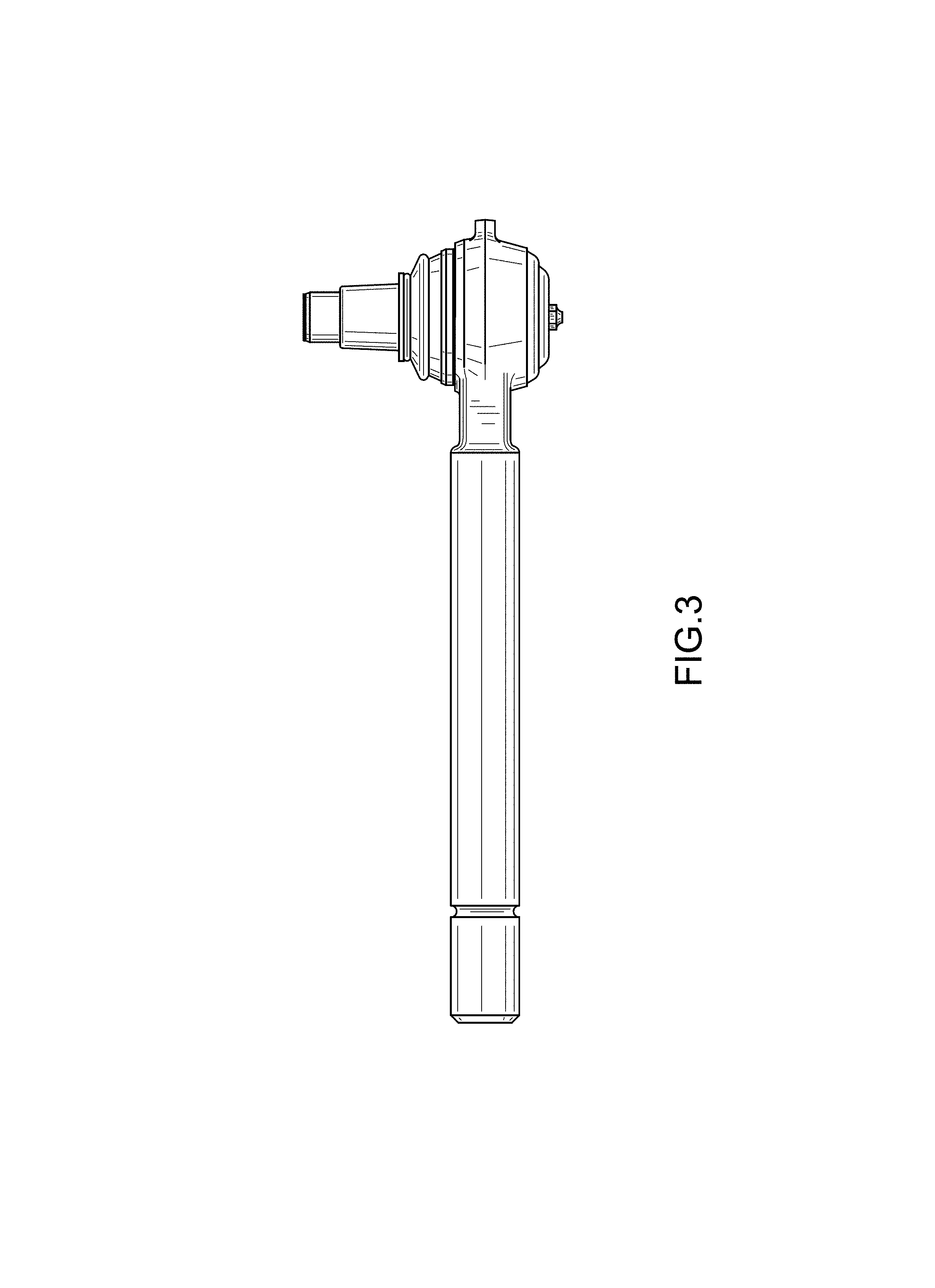
FIG. 3 is a back plan view thereof.
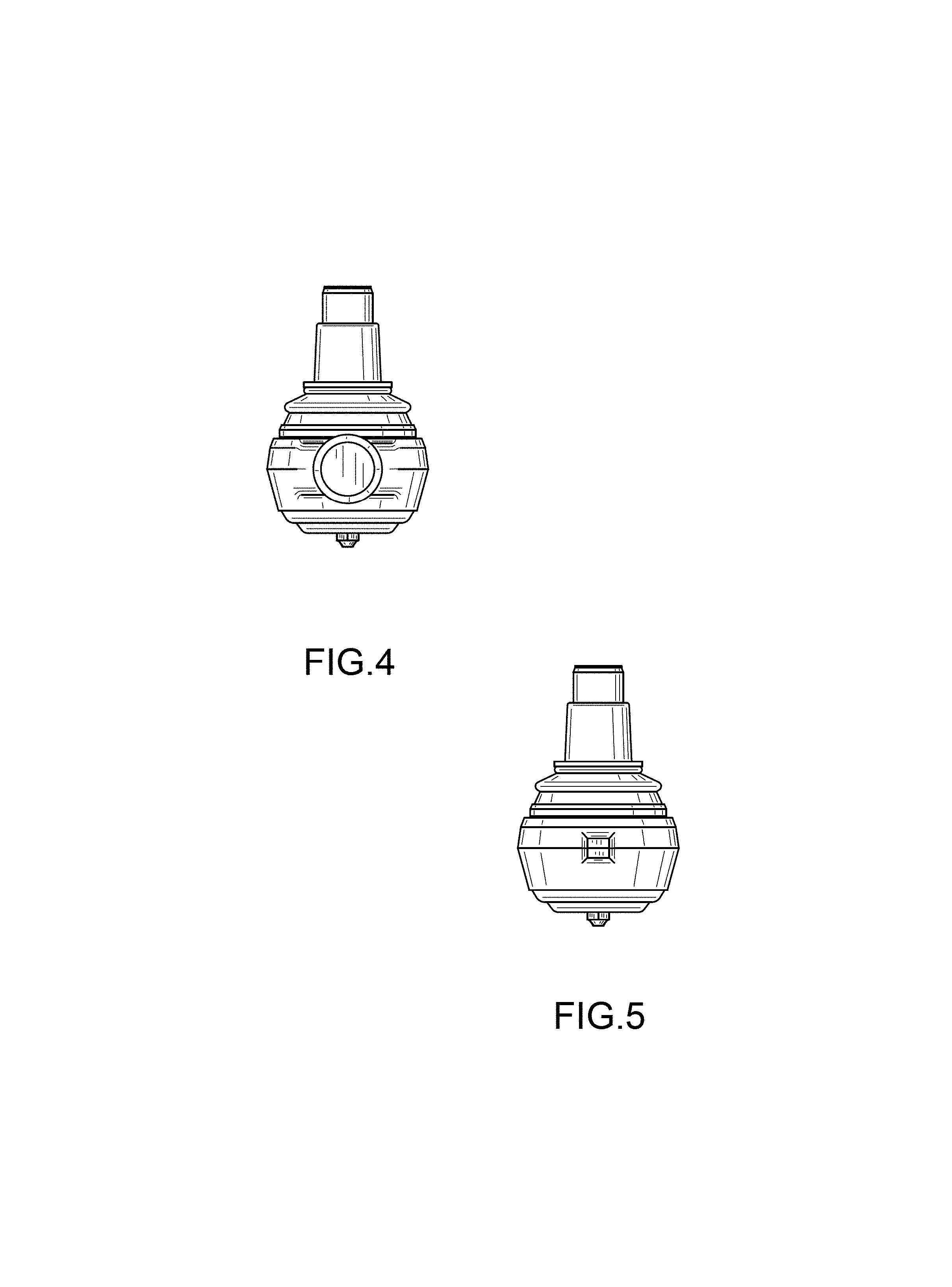
FIG. 4 is a right view thereof.
FIG. 5 is a left view thereof.
FIG. 6 is a top view thereof.
FIG. 7 is a bottom view thereof.
FIG. 8 is a perspective view of an embodiment of a tie rod end.
FIG. 9 is a front plan view thereof.
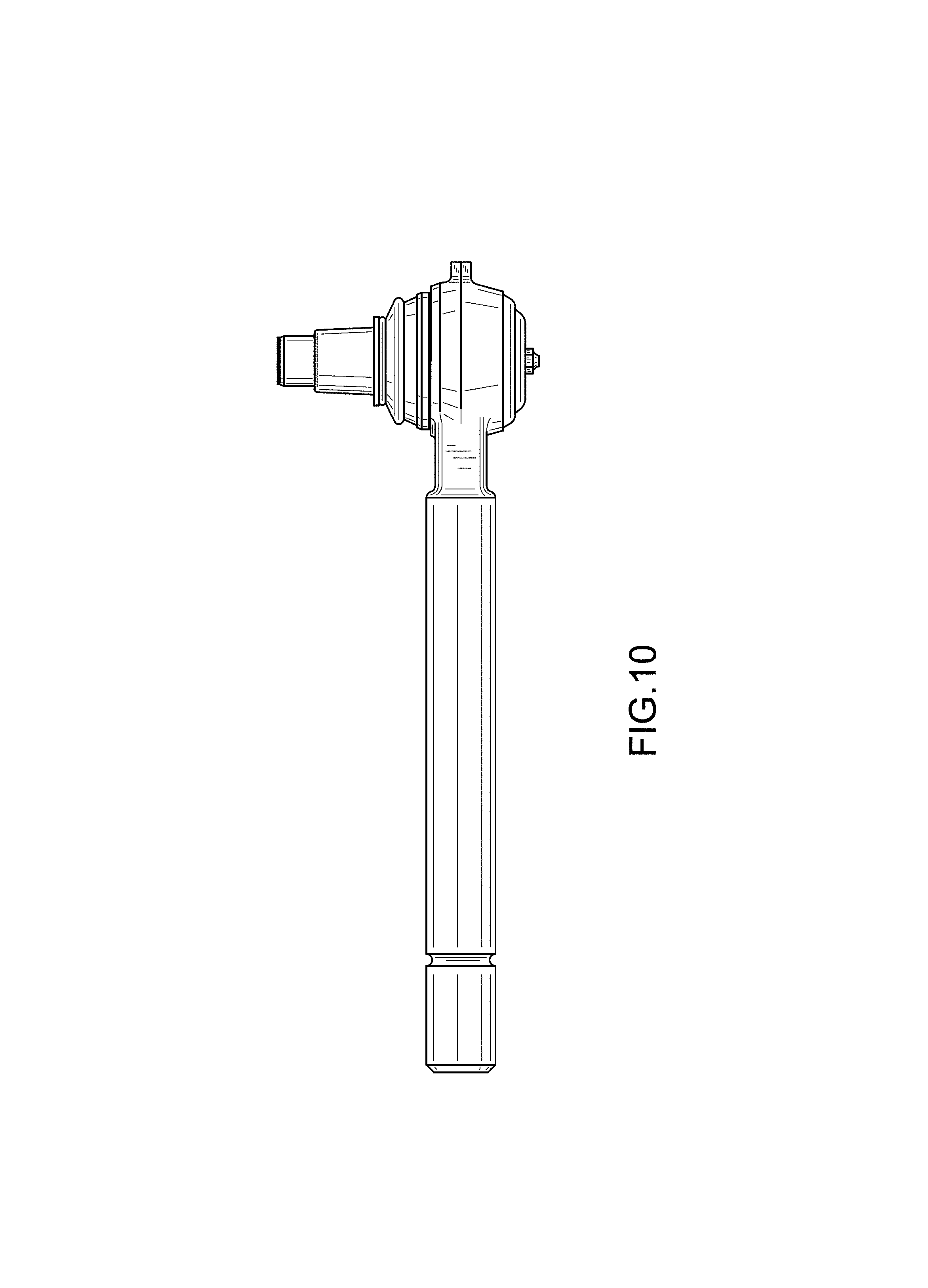
FIG. 10 is a back plan view thereof.
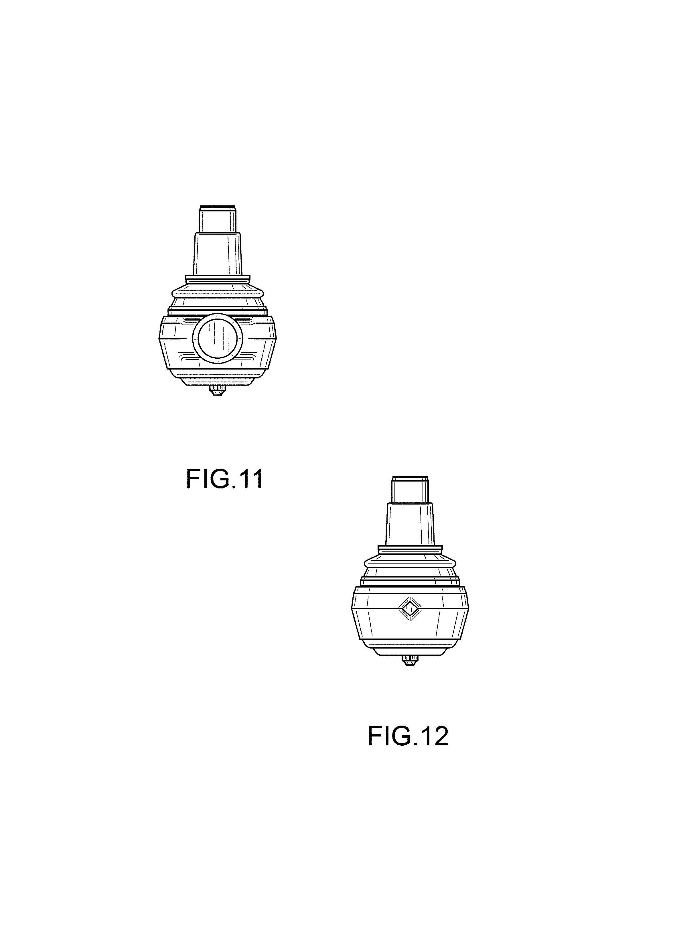
FIG. 11 is a right view thereof.
FIG. 12 is a left view thereof.
FIG. 13 is a top view thereof.
FIG. 14 is a bottom view thereof.
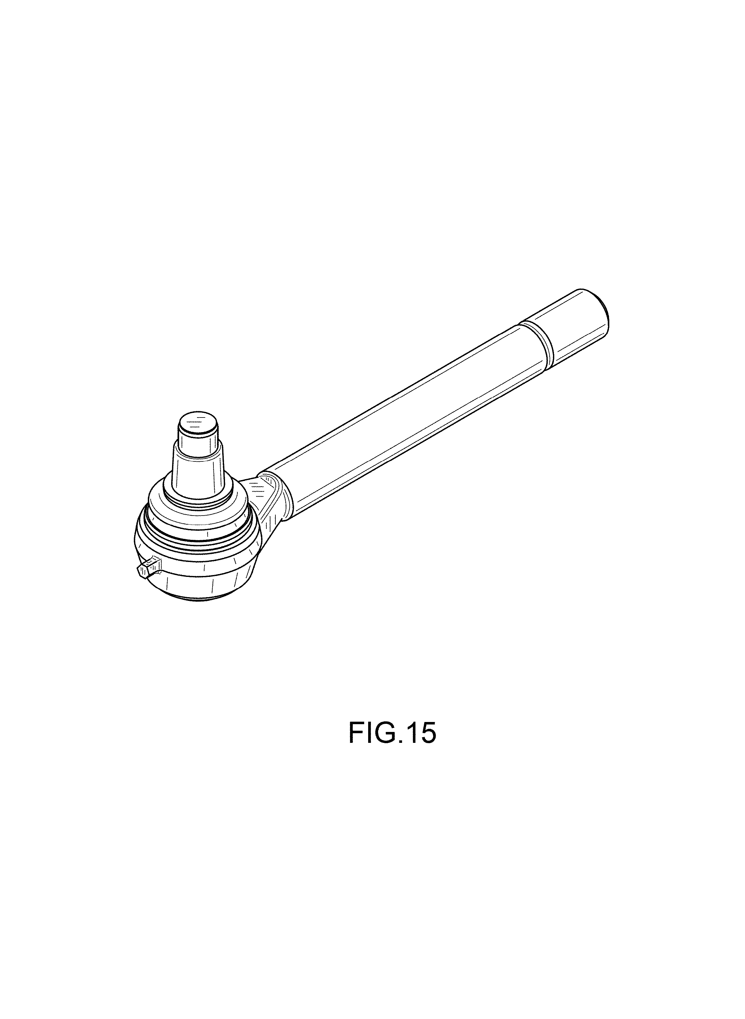
FIG. 15 is a perspective view of an embodiment of a tie rod end.
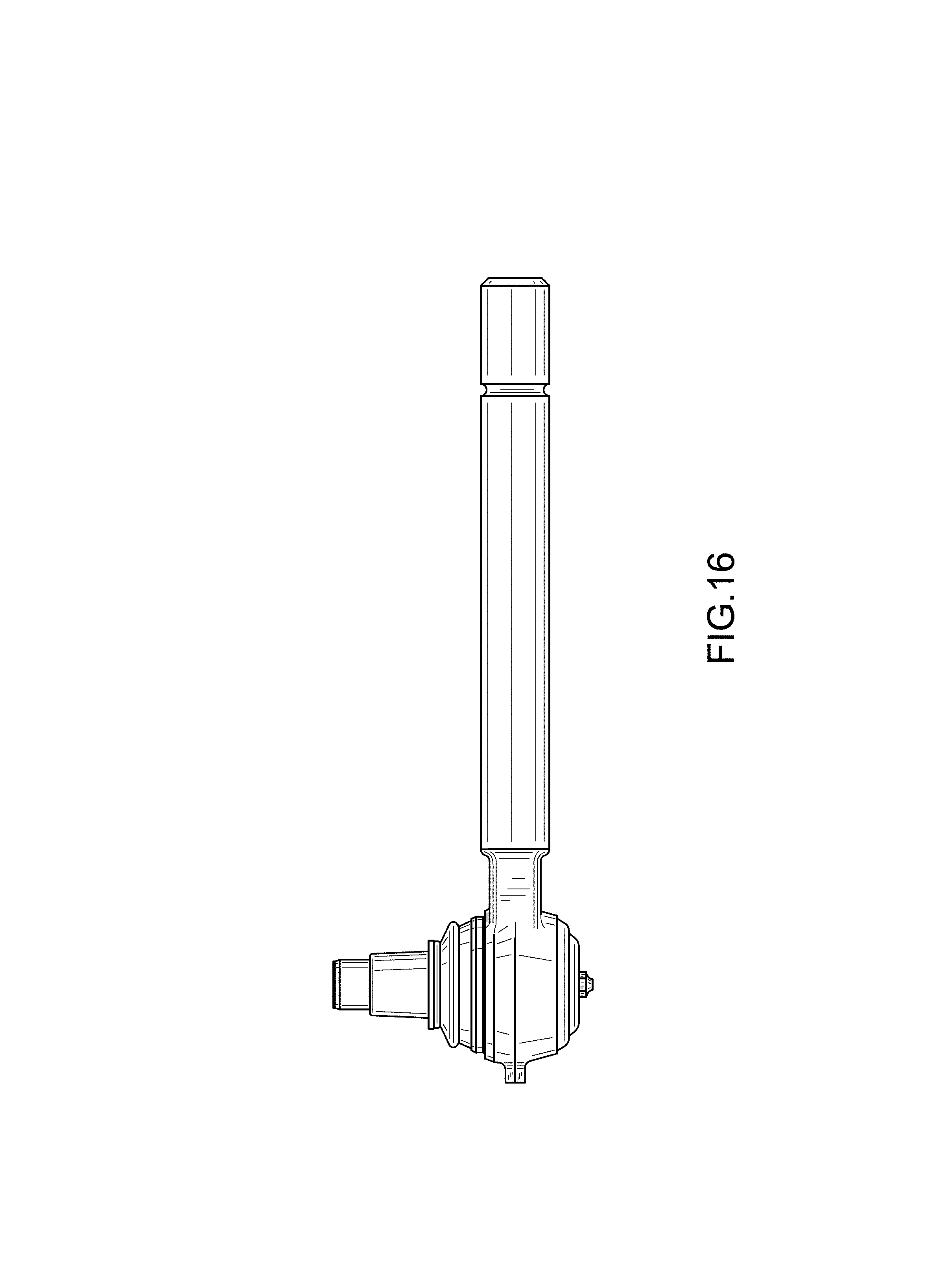
FIG. 16 is a front plan view thereof.
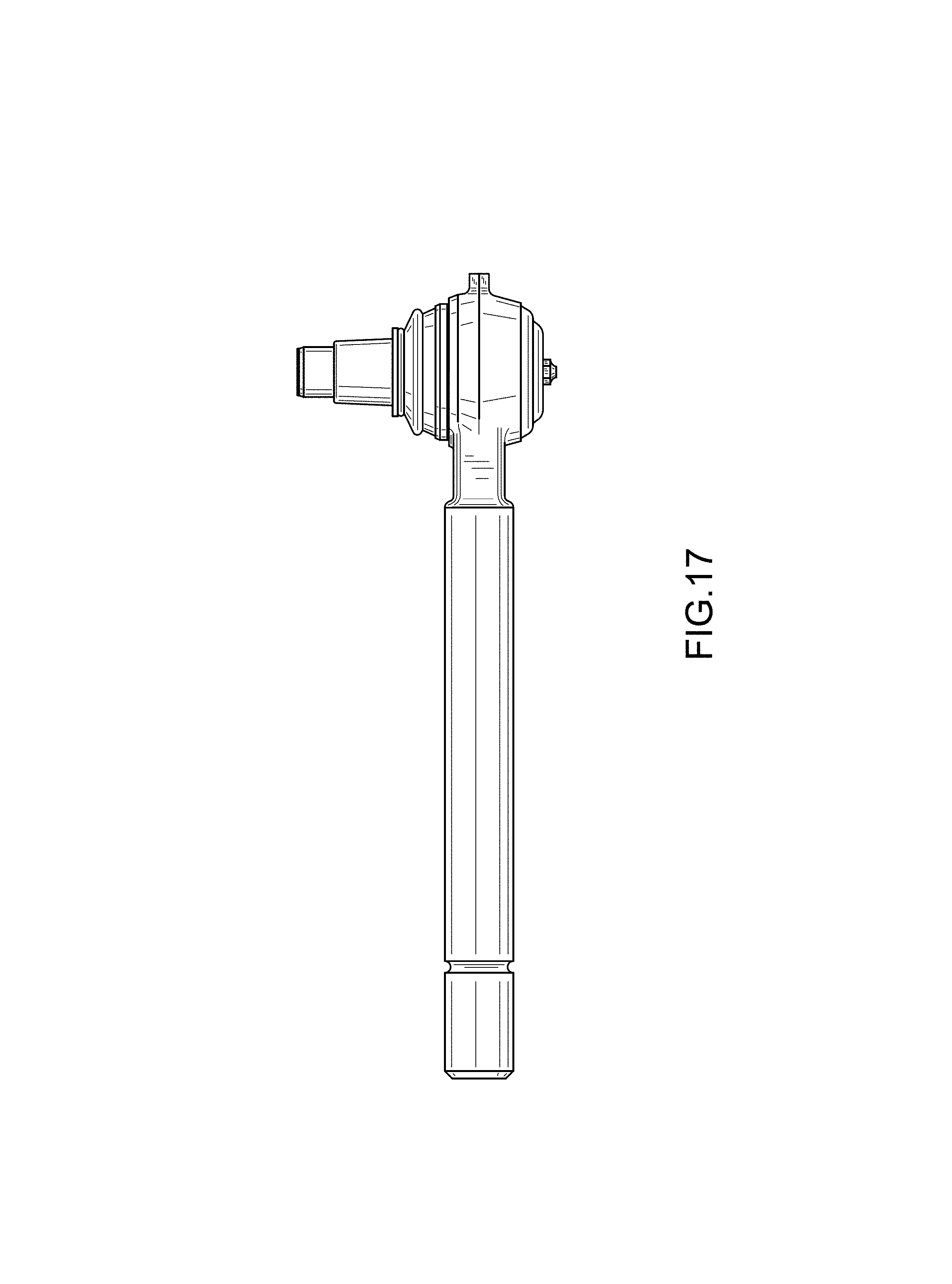
FIG. 17 is a back plan view thereof.
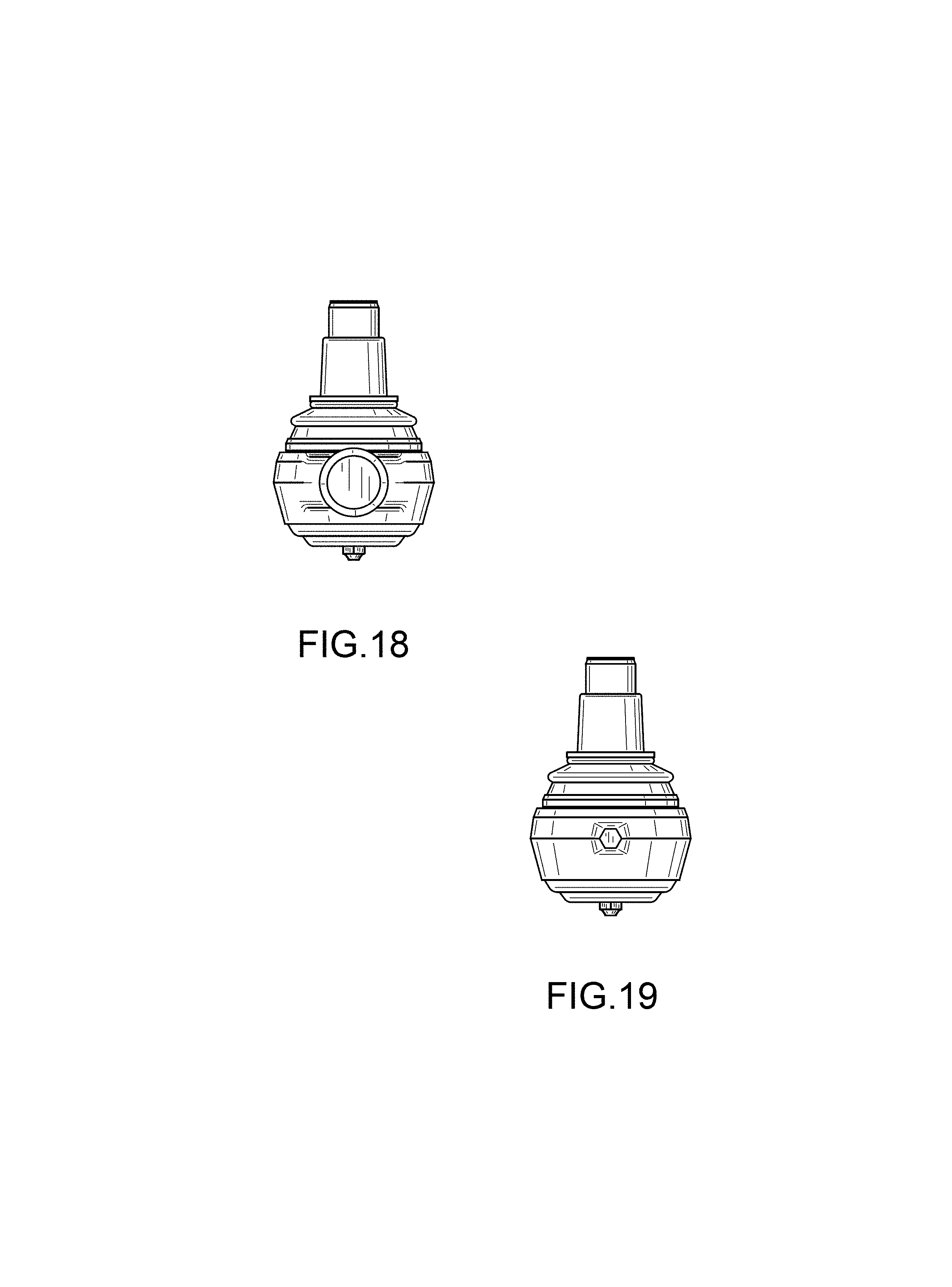
FIG. 18 is a right view thereof.
FIG. 19 is a left view thereof.
FIG. 20 is a top view thereof.
FIG. 21 is a bottom view thereof.
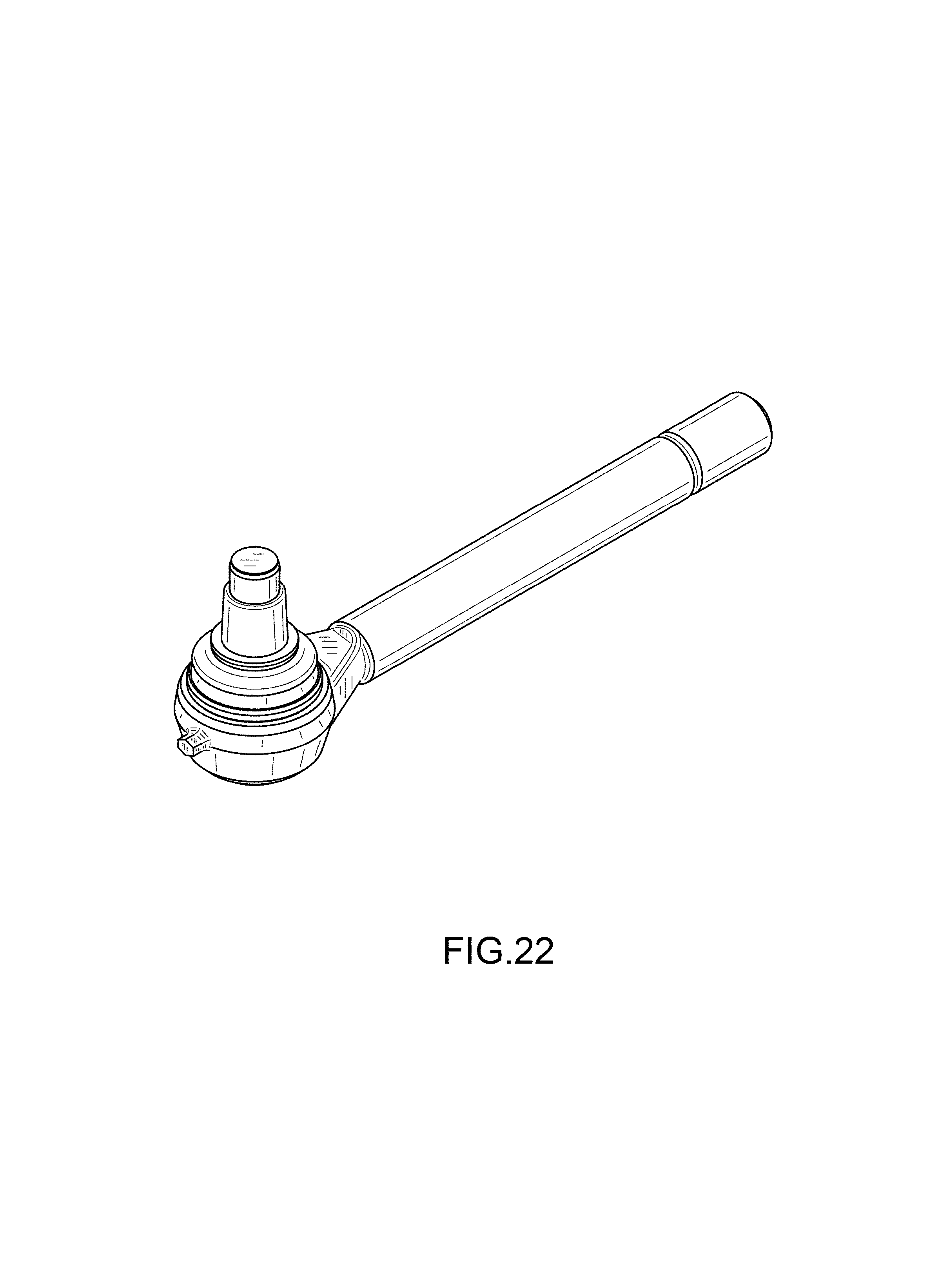
FIG. 22 is a perspective view of an embodiment of a tie rod end.
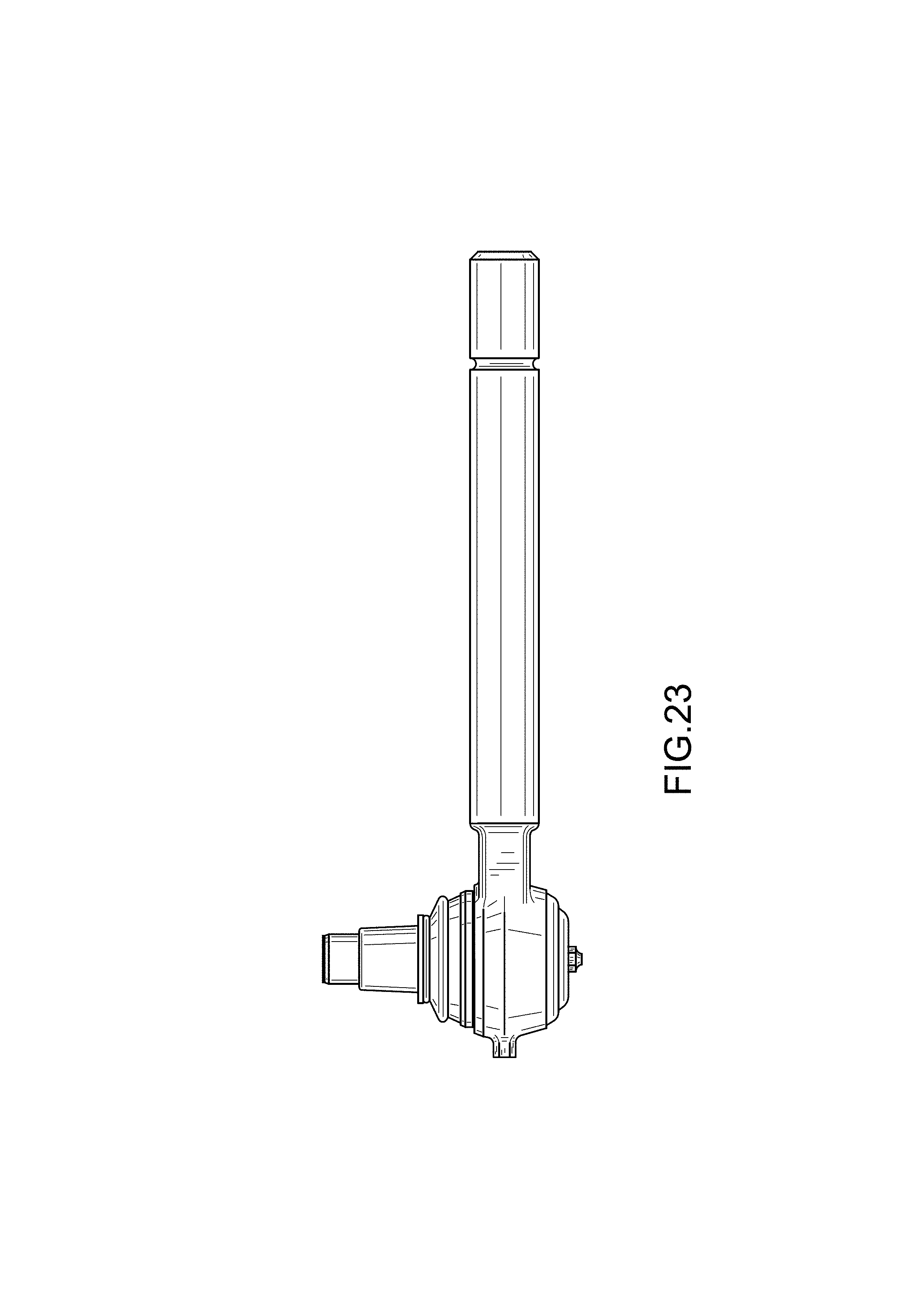
FIG. 23 is a front plan view thereof.
FIG. 24 is a back plan view thereof.
FIG. 25 is a right view thereof.
FIG. 26 is a left view thereof.
FIG. 27 is a top view thereof; and,
FIG. 28 is a bottom view thereof.
* * * * *
References
D00000
D00001
D00002
D00003
D00004
D00005
D00006
D00007
D00008
D00009
D00010
D00011
D00012
D00013
D00014
D00015

D00016
D00017
D00018

D00019

D00020

XML
uspto.report is an independent third-party trademark research tool that is not affiliated, endorsed, or sponsored by the United States Patent and Trademark Office (USPTO) or any other governmental organization. The information provided by uspto.report is based on publicly available data at the time of writing and is intended for informational purposes only.
While we strive to provide accurate and up-to-date information, we do not guarantee the accuracy, completeness, reliability, or suitability of the information displayed on this site. The use of this site is at your own risk. Any reliance you place on such information is therefore strictly at your own risk.
All official trademark data, including owner information, should be verified by visiting the official USPTO website at www.uspto.gov. This site is not intended to replace professional legal advice and should not be used as a substitute for consulting with a legal professional who is knowledgeable about trademark law.