Charging station for mobile robotic vacuum
Ebrahimi Afrouzi , et al. Sept
U.S. patent number D860,934 [Application Number D/617,846] was granted by the patent office on 2019-09-24 for charging station for mobile robotic vacuum. This patent grant is currently assigned to AI Incorporated. The grantee listed for this patent is Ali Ebrahimi Afrouzi, Shahin Fathi Djalali. Invention is credited to Ali Ebrahimi Afrouzi, Shahin Fathi Djalali.


View All Diagrams
| United States Patent | D860,934 |
| Ebrahimi Afrouzi , et al. | September 24, 2019 |
Charging station for mobile robotic vacuum
Claims
CLAIM The ornamental design for a charging station for mobile robotic vacuum, as shown and described.
| Inventors: | Ebrahimi Afrouzi; Ali (San Jose, CA), Fathi Djalali; Shahin (San Francisco, CA) | ||||||||||
|---|---|---|---|---|---|---|---|---|---|---|---|
| Applicant: |
|
||||||||||
| Assignee: | AI Incorporated (Toronto,
CA) |
||||||||||
| Appl. No.: | D/617,846 | ||||||||||
| Filed: | November 20, 2017 |
| Current U.S. Class: | D13/108 |
| Current International Class: | 1302 |
| Field of Search: | ;D13/107-110,118-119,184,199 ;D8/353,381 ;D14/251,253,432,434 ;D28/73 |
References Cited [Referenced By]
U.S. Patent Documents
| 7729801 | June 2010 | Abramson |
| D639735 | June 2011 | Lee |
| 8224487 | July 2012 | Yoo |
| 8299750 | October 2012 | Pai |
| D675154 | January 2013 | Nam |
| D691553 | October 2013 | Deoksang |
| D698310 | January 2014 | Yun |
| D709446 | July 2014 | Haug |
| D782412 | March 2017 | Kim |
| 9790700 | October 2017 | Tamar |
| 9851711 | December 2017 | Yoo |
| 9853468 | December 2017 | Ireland |
| 9884423 | February 2018 | Cohen |
| 9903130 | February 2018 | Witelson |
| 9907447 | March 2018 | Tanaka |
| D818433 | May 2018 | Ebrahimi Afrouzi |
| D818950 | May 2018 | Ebrahimi Afrouzi |
| D818951 | May 2018 | Ebrahimi Afrouzi |
| 10022029 | July 2018 | Machida |
Other References
|
BObsweep Pet Hair Robotic Vacuum Cleaner and Mop, bObsweep, reviewed on Sep. 29, 2014 on amazon.com, retrieved on Oct. 26, 2018, retrieved from the Internet URL: https://www.amazon.com/bObsweep-PetHair-Robotic-Vacuum-Cleaner/dp/B00XBRY- FVY/ref=sr_1_1?ie=UTF8&qid=1540566932&sr=8-1&keywords=bobsweep+char. cited by examiner. |
Primary Examiner: Rivard; Jennifer
Assistant Examiner: Ofstun; Alison M
Description
FIG. 1 is a front elevation view of a charging station for mobile robotic vacuum showing our new design, showing the prongs in a retracted position of use;
FIG. 2 is a top view thereof;
FIG. 3 is a bottom view thereof;
FIG. 4 is a right side elevation view thereof, the left side being a mirror image thereof;
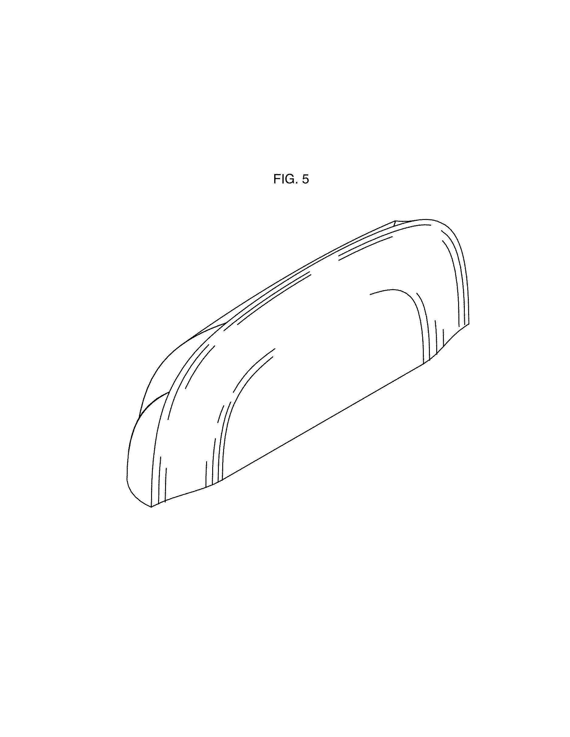
FIG. 5 is a rear perspective view thereof;
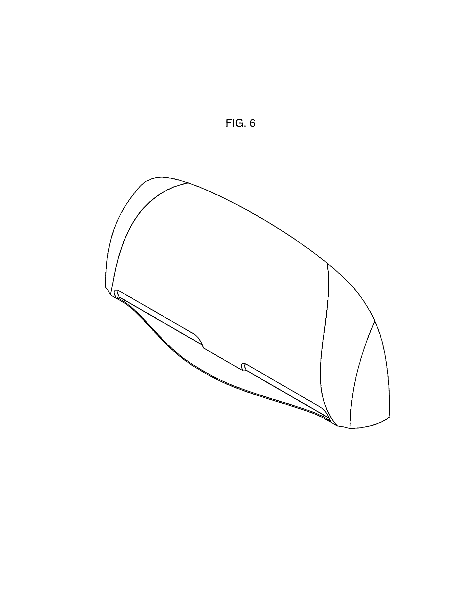
FIG. 6 is a front perspective view thereof;
FIG. 7 is a front elevation thereof, showing the prongs in an extended position of use;
FIG. 8 is a top view thereof;
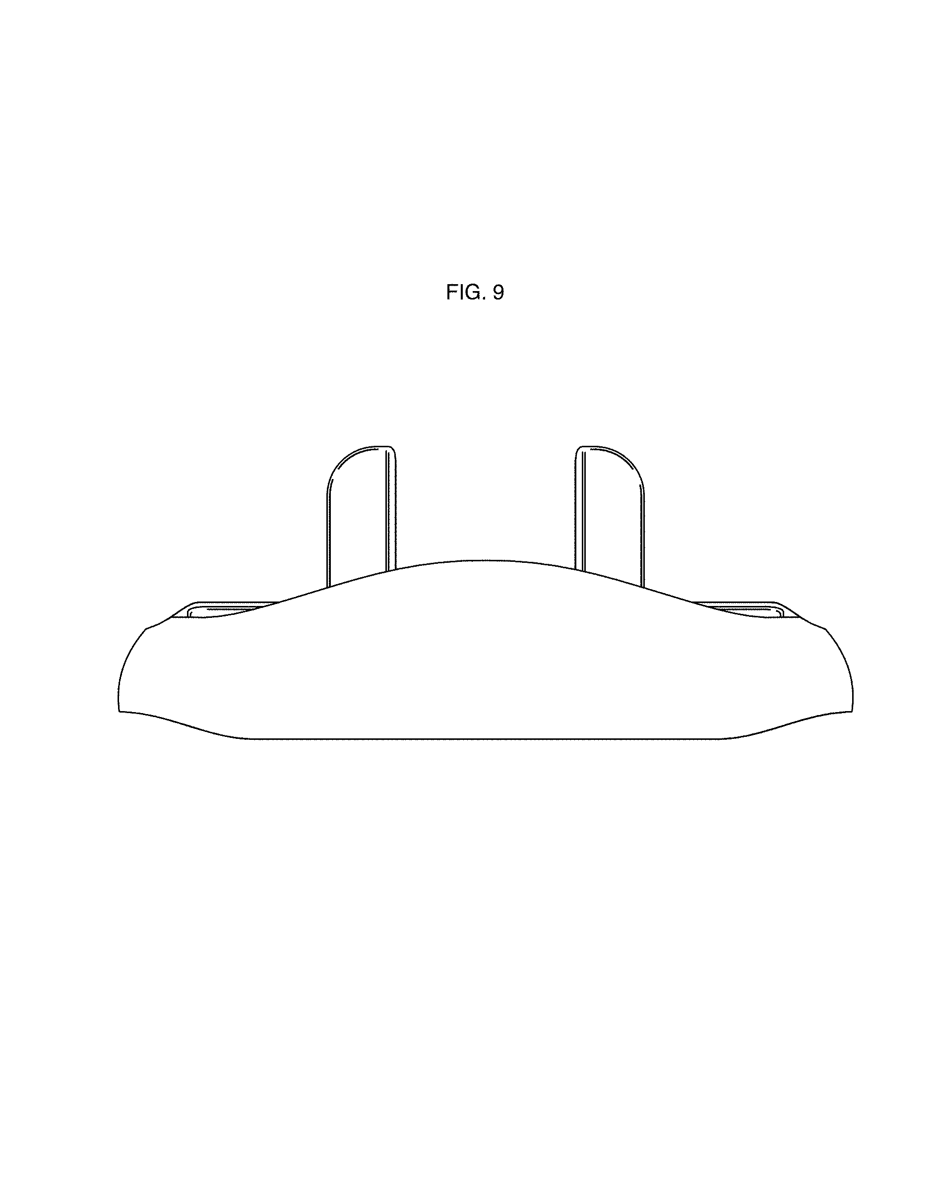
FIG. 9 is a bottom view thereof;
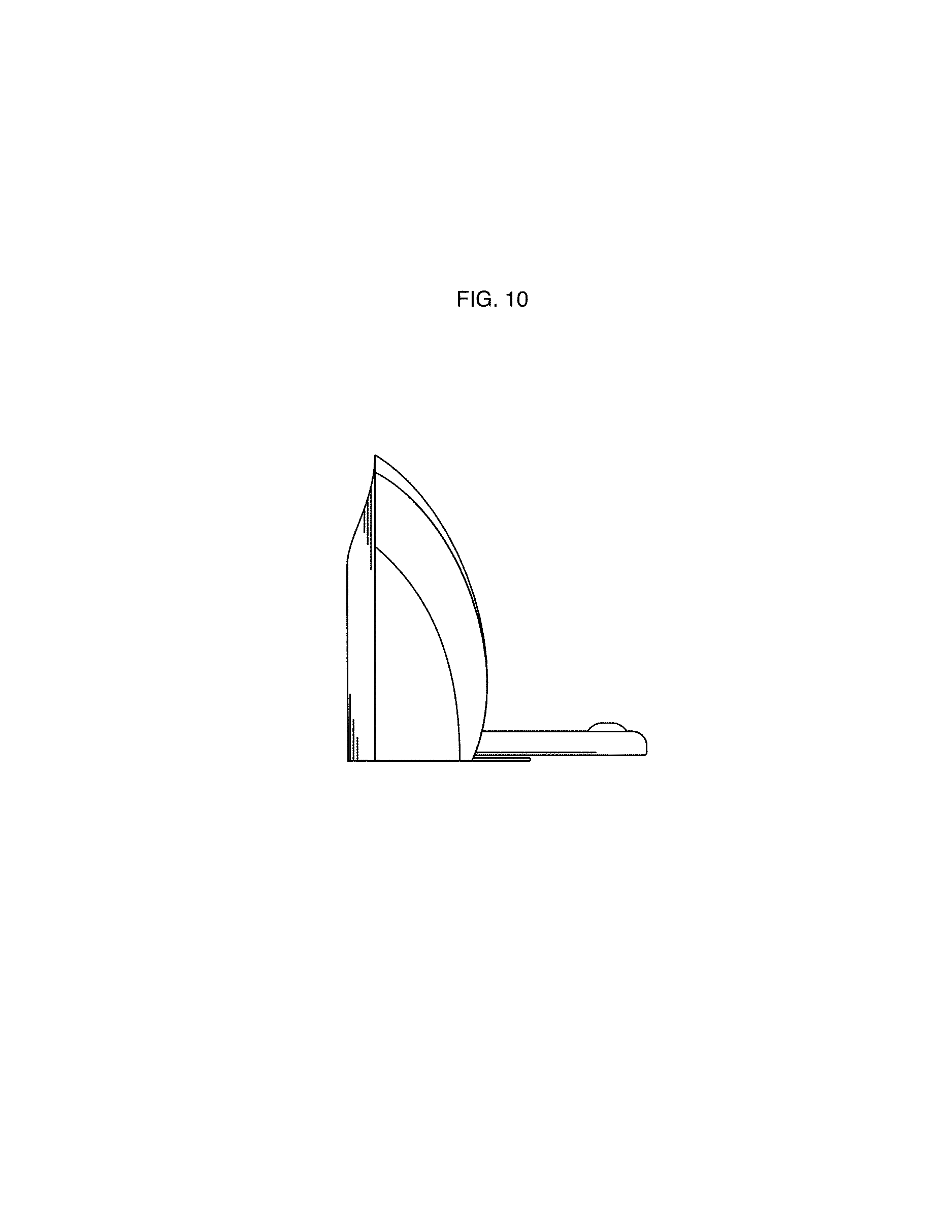
FIG. 10 is a right side elevation view thereof, the left side being a mirror image thereof;
FIG. 11 is a front perspective view thereof;
FIG. 12 is a rear perspective view thereof; and,
FIG. 13 is a front perspective view thereof, showing the prongs in a partially extended position of use.
* * * * *
References
D00000
D00001
D00002
D00003
D00004
D00005
D00006
D00007
D00008
D00009
D00010
D00011
D00012

D00013

XML
uspto.report is an independent third-party trademark research tool that is not affiliated, endorsed, or sponsored by the United States Patent and Trademark Office (USPTO) or any other governmental organization. The information provided by uspto.report is based on publicly available data at the time of writing and is intended for informational purposes only.
While we strive to provide accurate and up-to-date information, we do not guarantee the accuracy, completeness, reliability, or suitability of the information displayed on this site. The use of this site is at your own risk. Any reliance you place on such information is therefore strictly at your own risk.
All official trademark data, including owner information, should be verified by visiting the official USPTO website at www.uspto.gov. This site is not intended to replace professional legal advice and should not be used as a substitute for consulting with a legal professional who is knowledgeable about trademark law.