System including multiple instrument modules and arrangement thereof
LiCalzi , et al. Sep
U.S. patent number D858,791 [Application Number D/635,513] was granted by the patent office on 2019-09-03 for system including multiple instrument modules and arrangement thereof. This patent grant is currently assigned to Siemens Healthcare Diagnostics Inc.. The grantee listed for this patent is Siemens Healthcare Diagnostics Inc.. Invention is credited to Justin Cumming, Robert Faranda, Josh Hartl, Youngsang Lee, Daniel LiCalzi, Scott Salmon, Richard Watson.


View All Diagrams
| United States Patent | D858,791 |
| LiCalzi , et al. | September 3, 2019 |
System including multiple instrument modules and arrangement thereof
Claims
CLAIM We claim the ornamental design for an system including multiple instrument modules and arrangement thereof, as shown and described.
| Inventors: | LiCalzi; Daniel (New York, NY), Lee; Youngsang (Flushing, NY), Faranda; Robert (Boxborough, MA), Watson; Richard (Norwell, MA), Cumming; Justin (Topsfield, MA), Salmon; Scott (Tenafly, NJ), Hartl; Josh (Philadelphia, PA) | ||||||||||
|---|---|---|---|---|---|---|---|---|---|---|---|
| Applicant: |
|
||||||||||
| Assignee: | Siemens Healthcare Diagnostics
Inc. (Tarrytown, NY) |
||||||||||
| Appl. No.: | D/635,513 | ||||||||||
| Filed: | January 31, 2018 |
Related U.S. Patent Documents
| Application Number | Filing Date | Patent Number | Issue Date | ||
|---|---|---|---|---|---|
| 29569429 | Jun 27, 2016 | D816242 | |||
| Current U.S. Class: | D24/216 |
| Current International Class: | 2401 |
| Field of Search: | ;D24/216,111,127,107,169,186,217,219,223-224,231-234 ;D10/46,70,81,97 ;422/1,62-65,67,68.1,70,81,129,500,506,561,FOR106 ;435/287.1,287.3 ;436/43,45,47 ;600/300,301,368,372,481,529,544,554,561 ;607/4,5,9,30 |
References Cited [Referenced By]
U.S. Patent Documents
| D645367 | September 2011 | Hayashi |
| D669189 | October 2012 | Liu |
| D676143 | February 2013 | Liu |
| D676568 | February 2013 | Liu |
| D685483 | July 2013 | LiCalzi |
| D735878 | August 2015 | Chang |
| D738243 | September 2015 | Selberg |
| D804681 | December 2017 | LiCalzi |
| D806259 | December 2017 | LiCalzi |
| D810956 | February 2018 | LiCalzi |
| D812241 | March 2018 | LiCalzi |
| D813410 | March 2018 | LiCalzi |
| D816238 | April 2018 | LiCalzi |
| D816239 | April 2018 | LiCalzi |
| D816240 | April 2018 | LiCalzi |
| D816241 | April 2018 | LiCalzi |
| D816242 | April 2018 | LiCalzi |
| D816859 | May 2018 | LiCalzi |
| D816860 | May 2018 | LiCalzi |
| D820995 | June 2018 | LiCalzi |
| D826423 | August 2018 | LiCalzi |
| D826424 | August 2018 | LiCalzi |
Assistant Examiner: Booker; Mark
Description
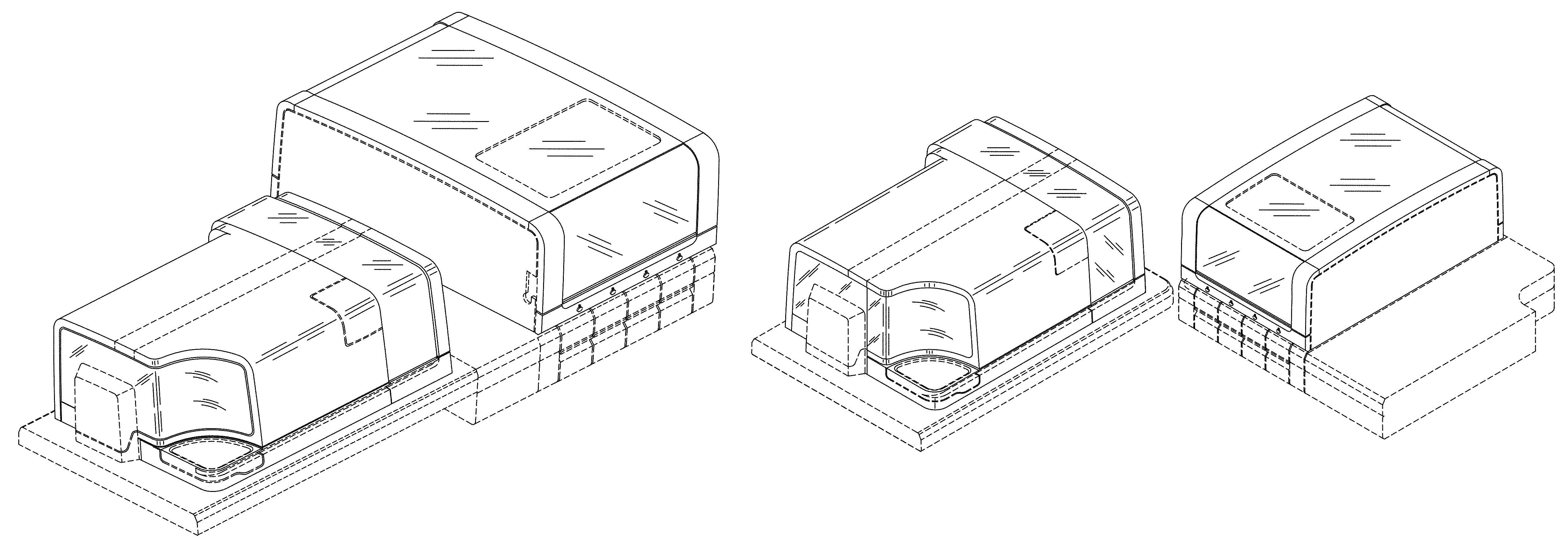
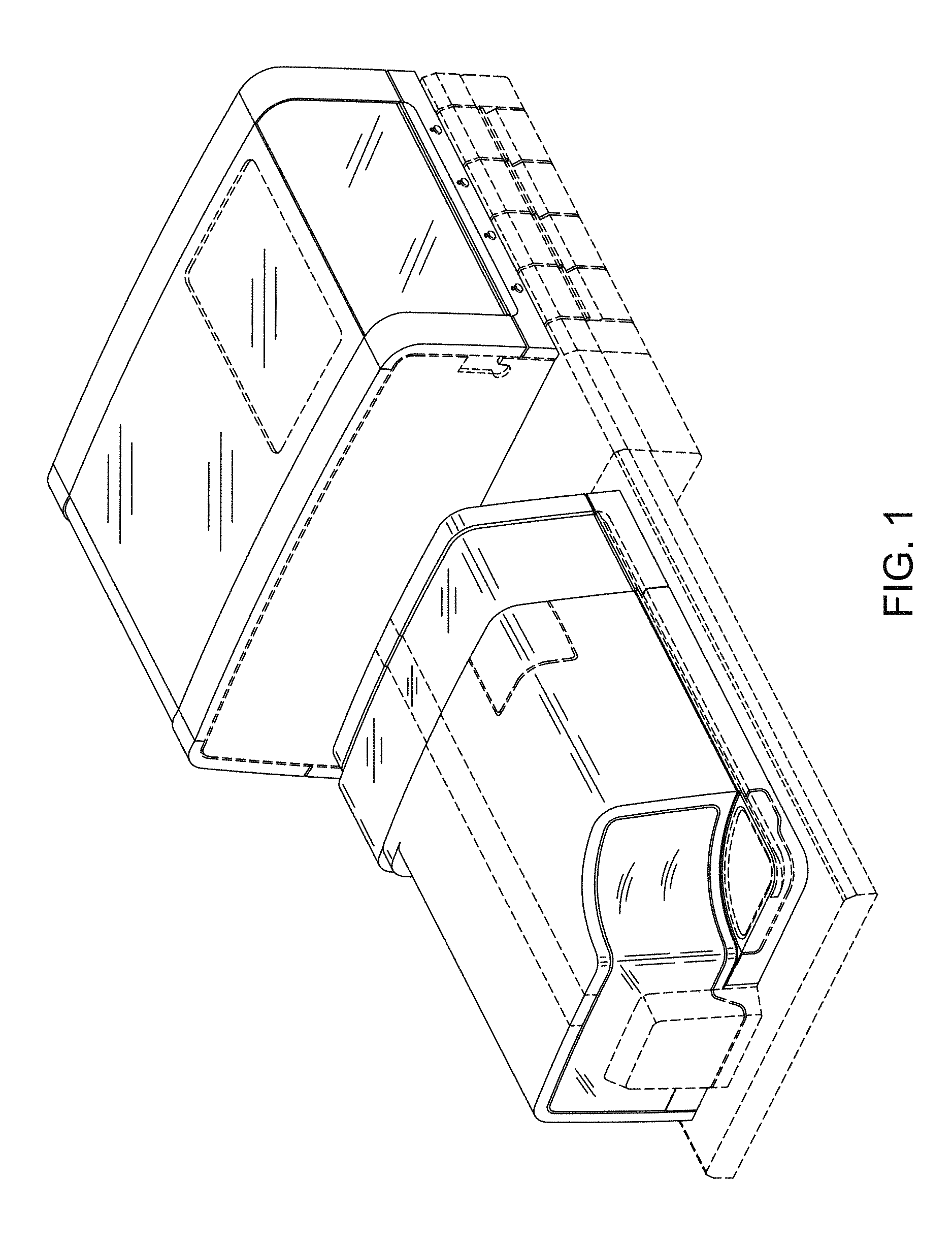
FIG. 1 is a front perspective view of a system including multiple instrument modules and arrangement thereof in accordance with a first embodiment;
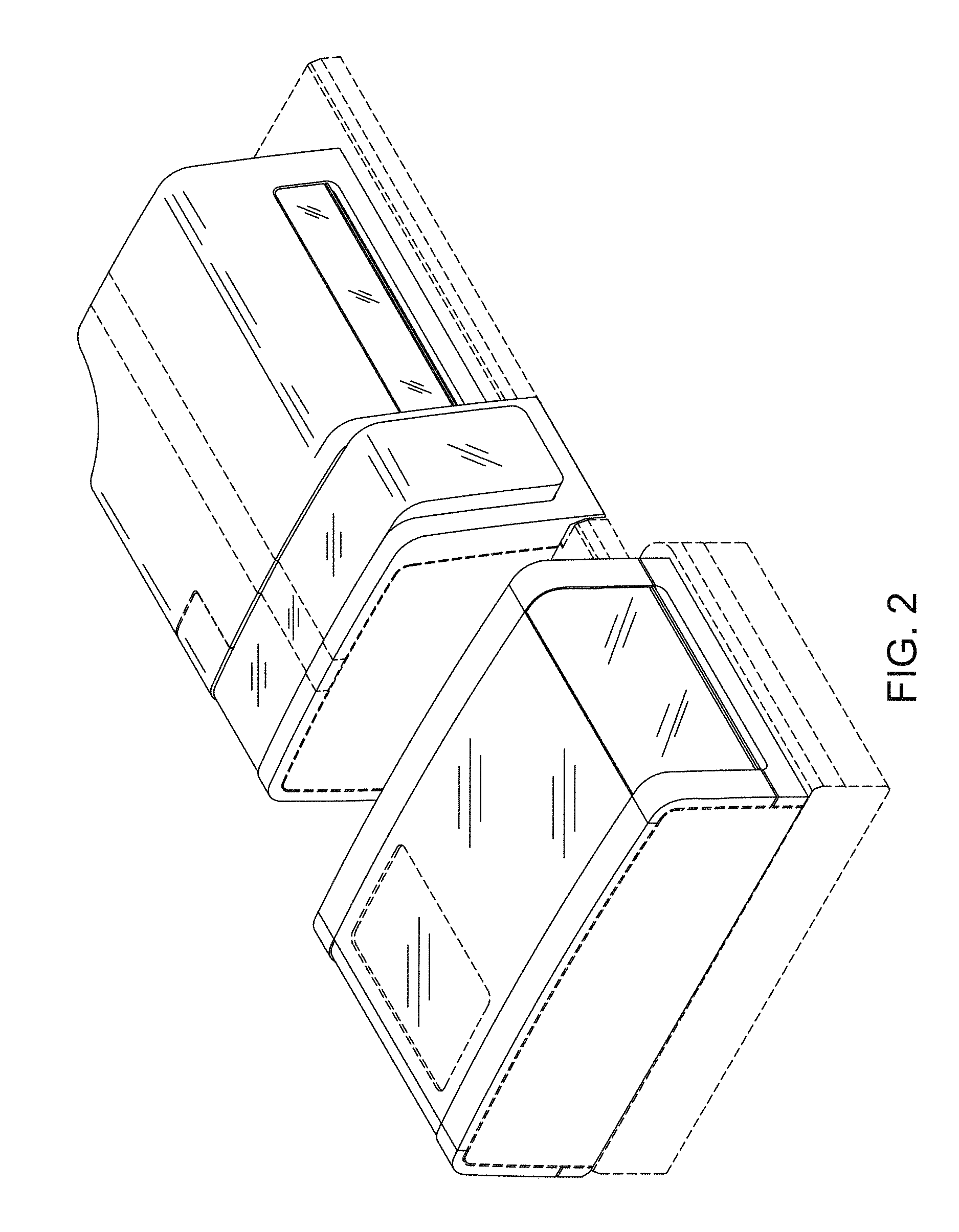
FIG. 2 is a rear perspective view of a system including multiple instrument modules and arrangement thereof;
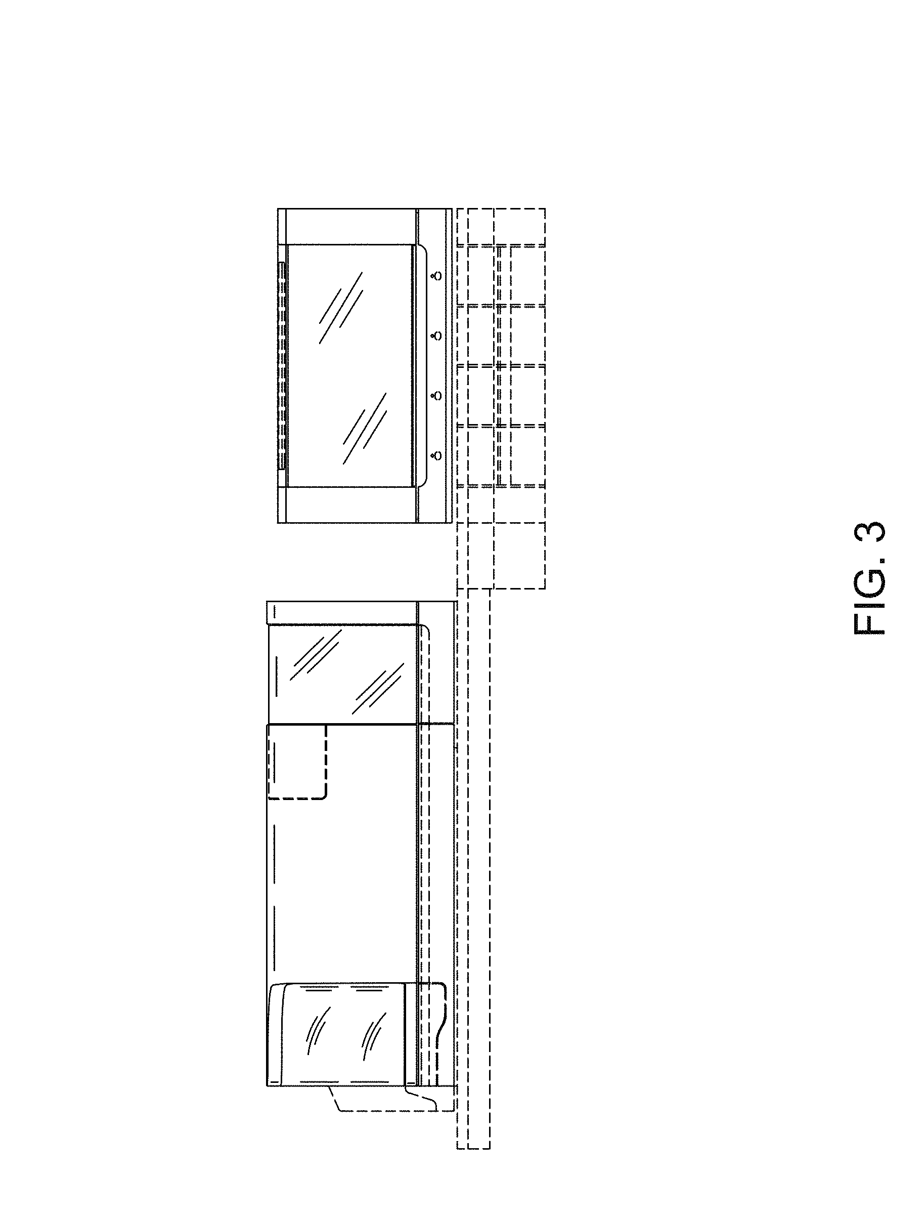
FIG. 3 is a front elevational view of a system including multiple instrument modules and arrangement thereof;
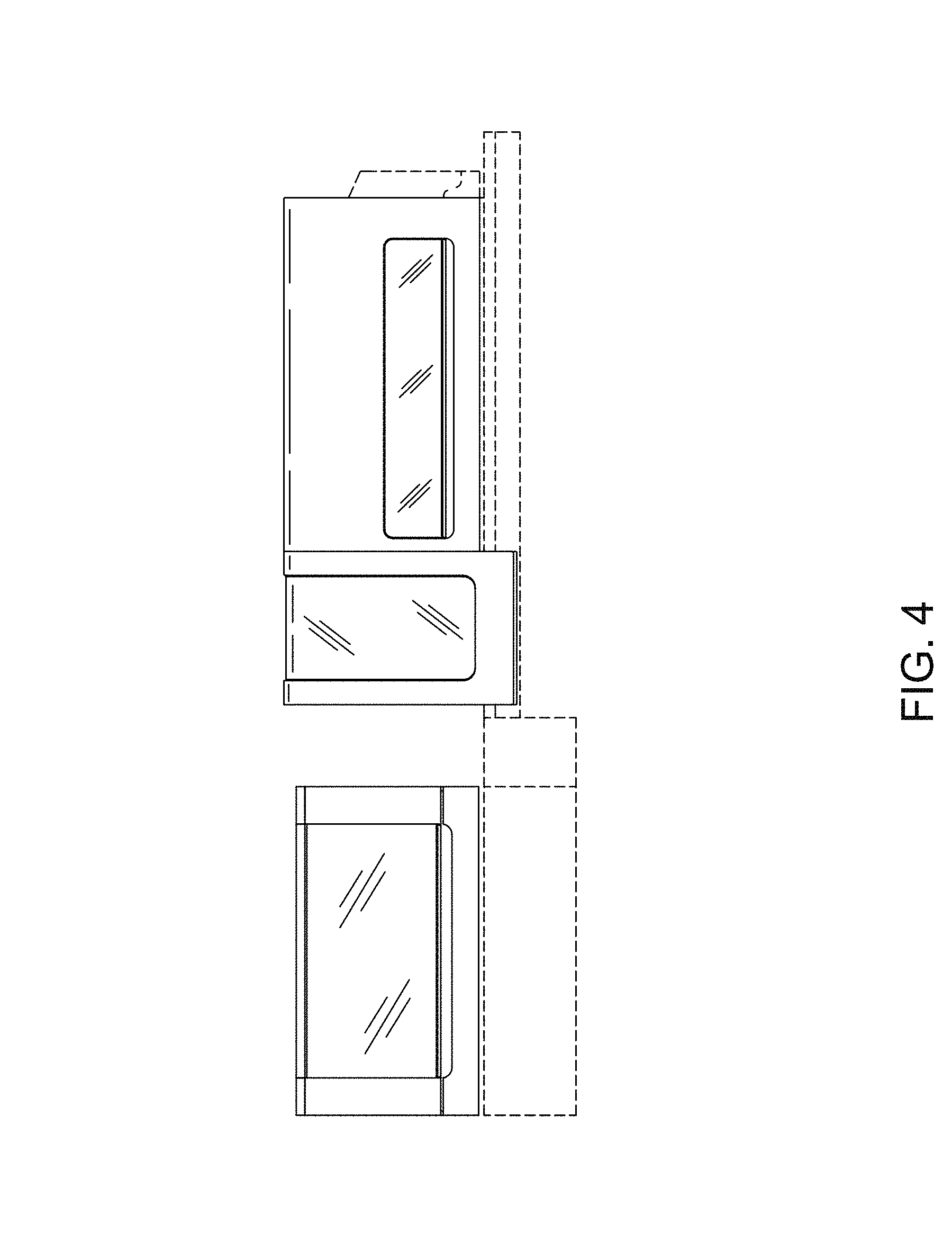
FIG. 4 is a rear elevational view of a system including multiple instrument modules and arrangement thereof;
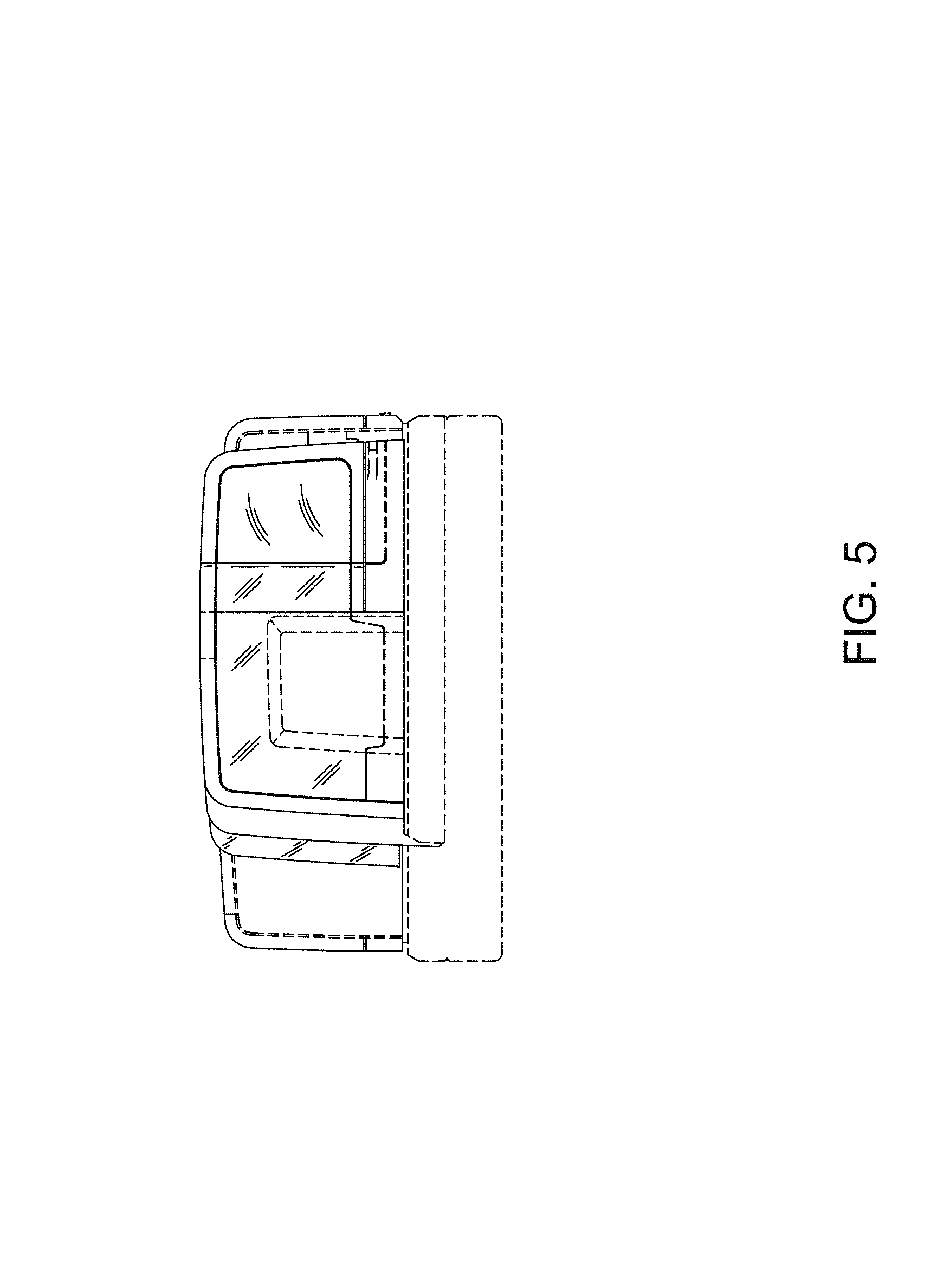
FIG. 5 is a left side elevational view of a system including multiple instrument modules and arrangement thereof;
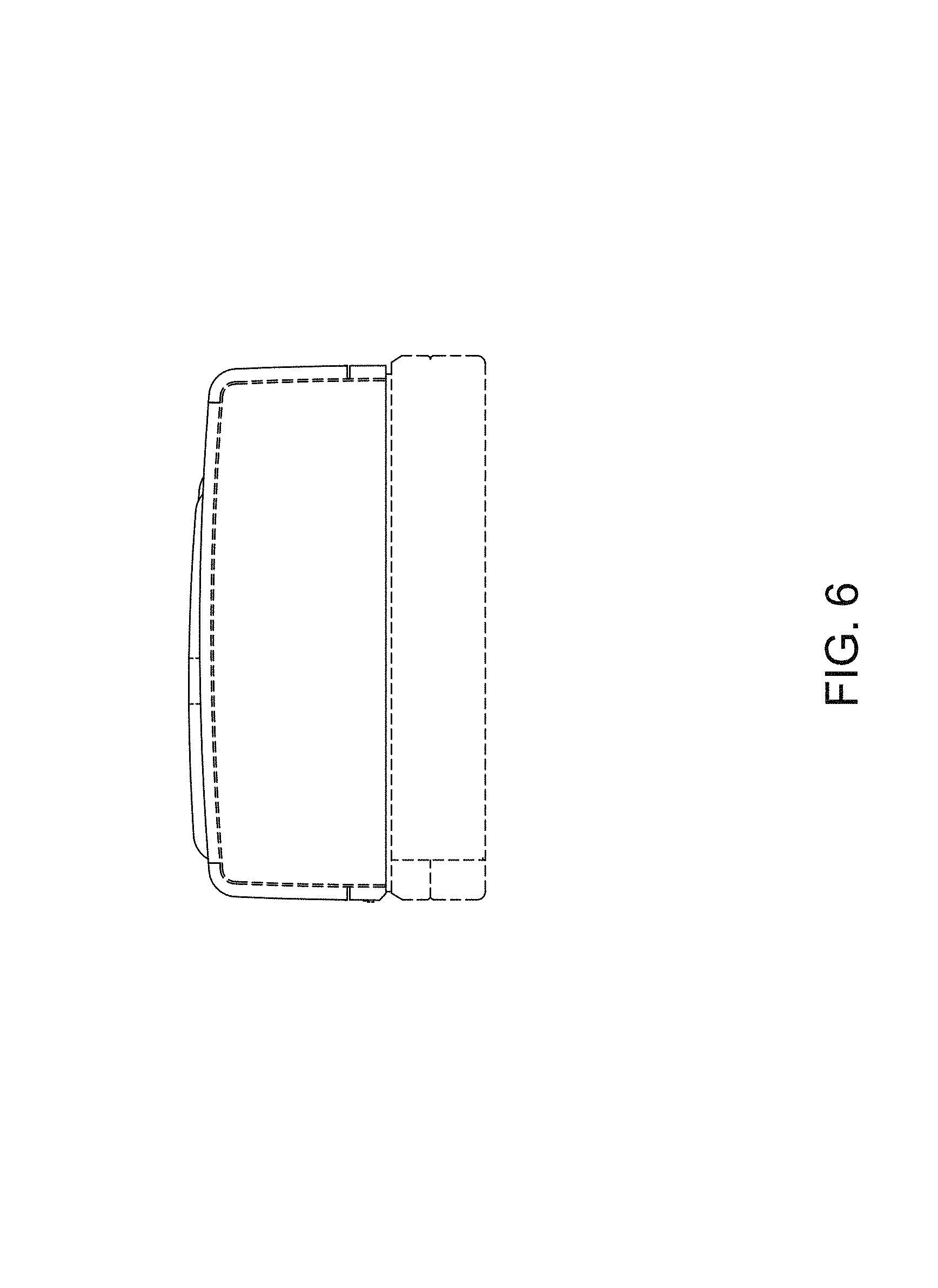
FIG. 6 is a right side elevational view of a system including multiple instrument modules and arrangement thereof;
FIG. 7 is a top view of a system including multiple instrument modules and arrangement thereof;
FIG. 8 is a bottom view of a system including multiple instrument modules and arrangement thereof;
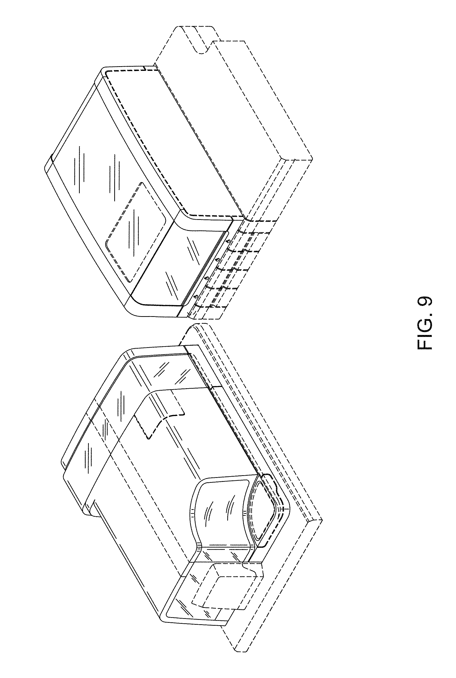
FIG. 9 is a front perspective view of a system including multiple instrument modules and arrangement thereof in accordance with a second embodiment;
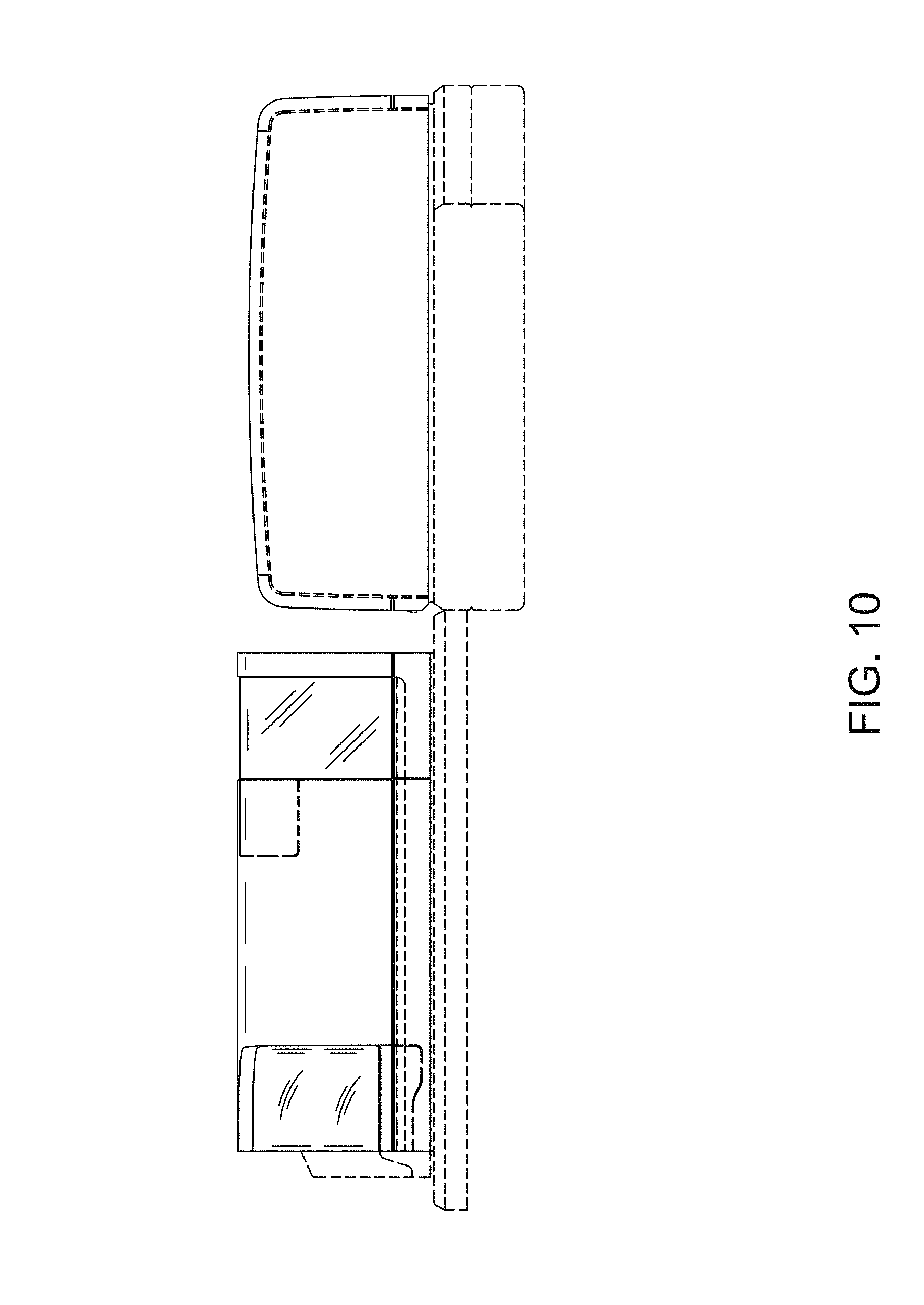
FIG. 10 is a front elevational view of a system including multiple instrument modules and arrangement thereof;
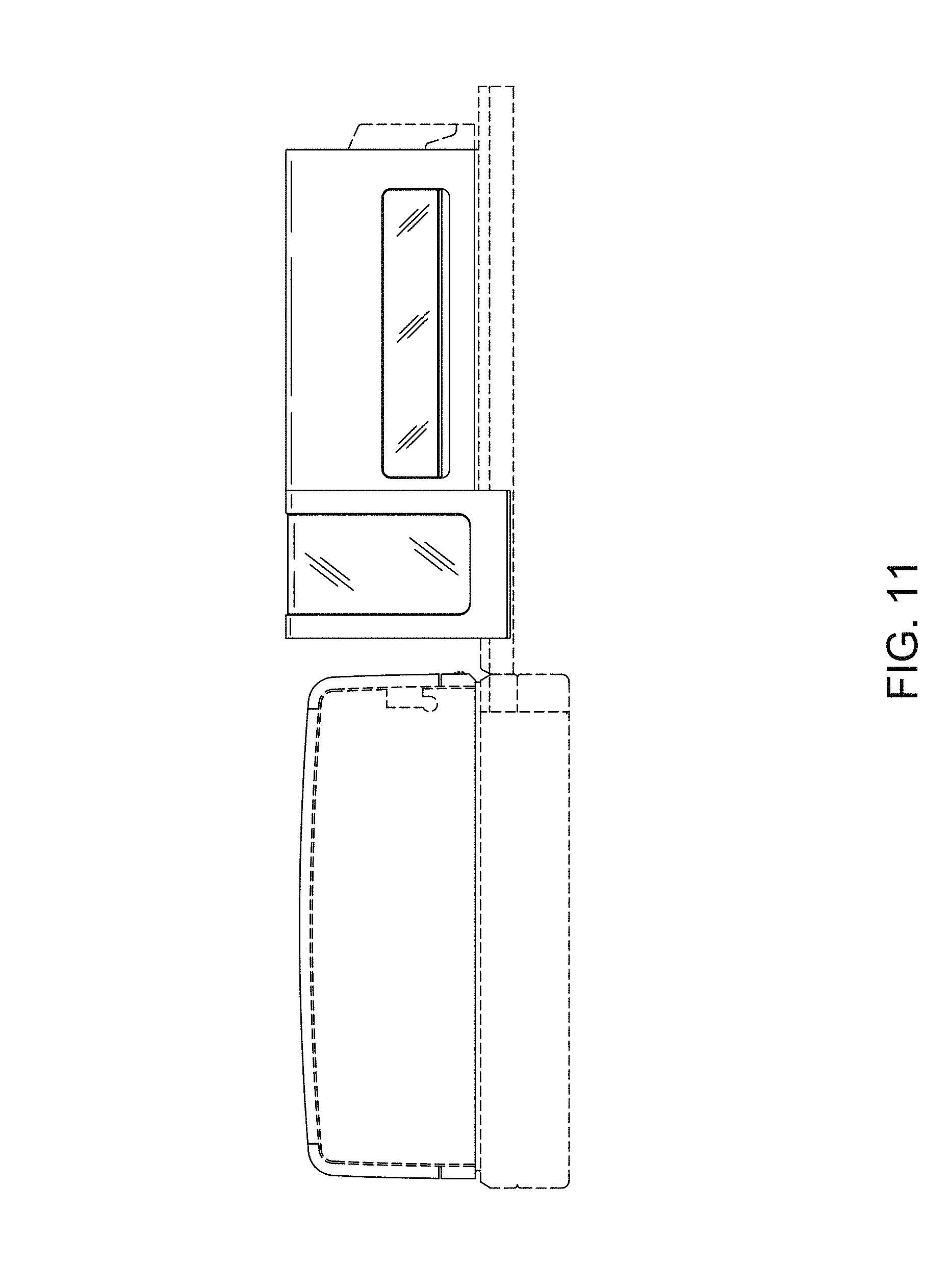
FIG. 11 a rear elevational view of a system including multiple instrument modules and arrangement thereof;
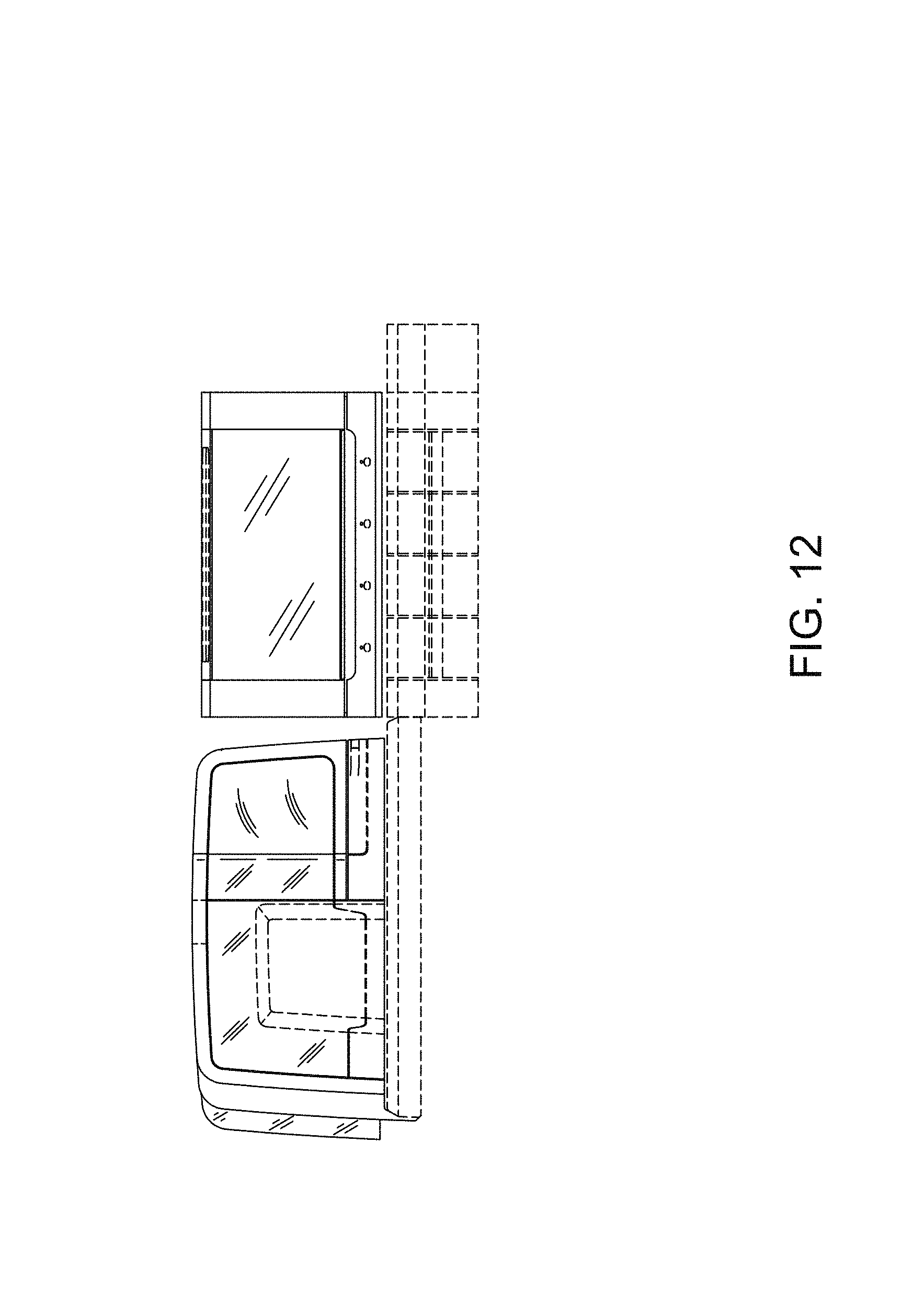
FIG. 12 is a left side elevational view of a system including multiple instrument modules and arrangement thereof;
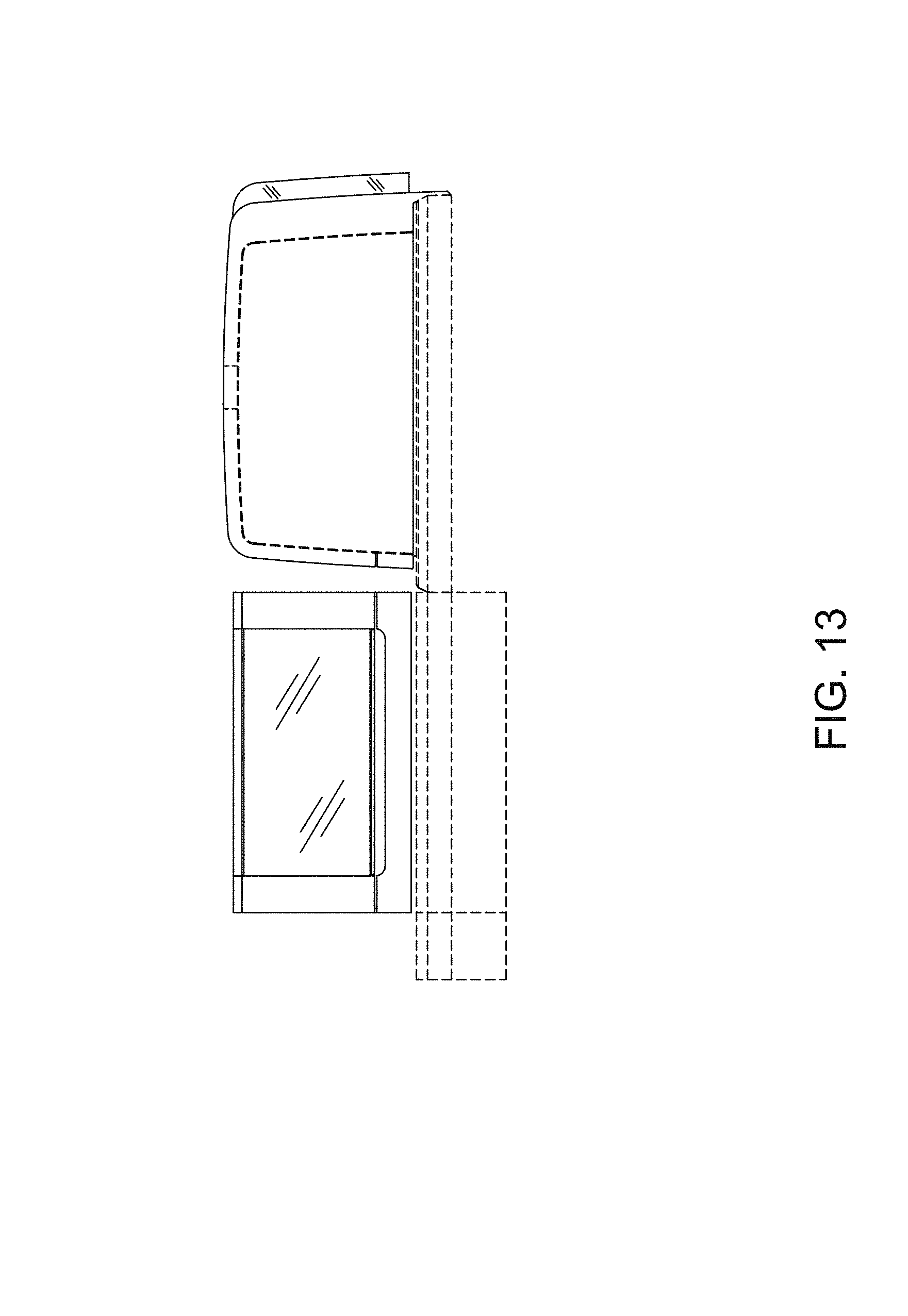
FIG. 13 is a right side elevational view of a system including multiple instrument modules and arrangement thereof;
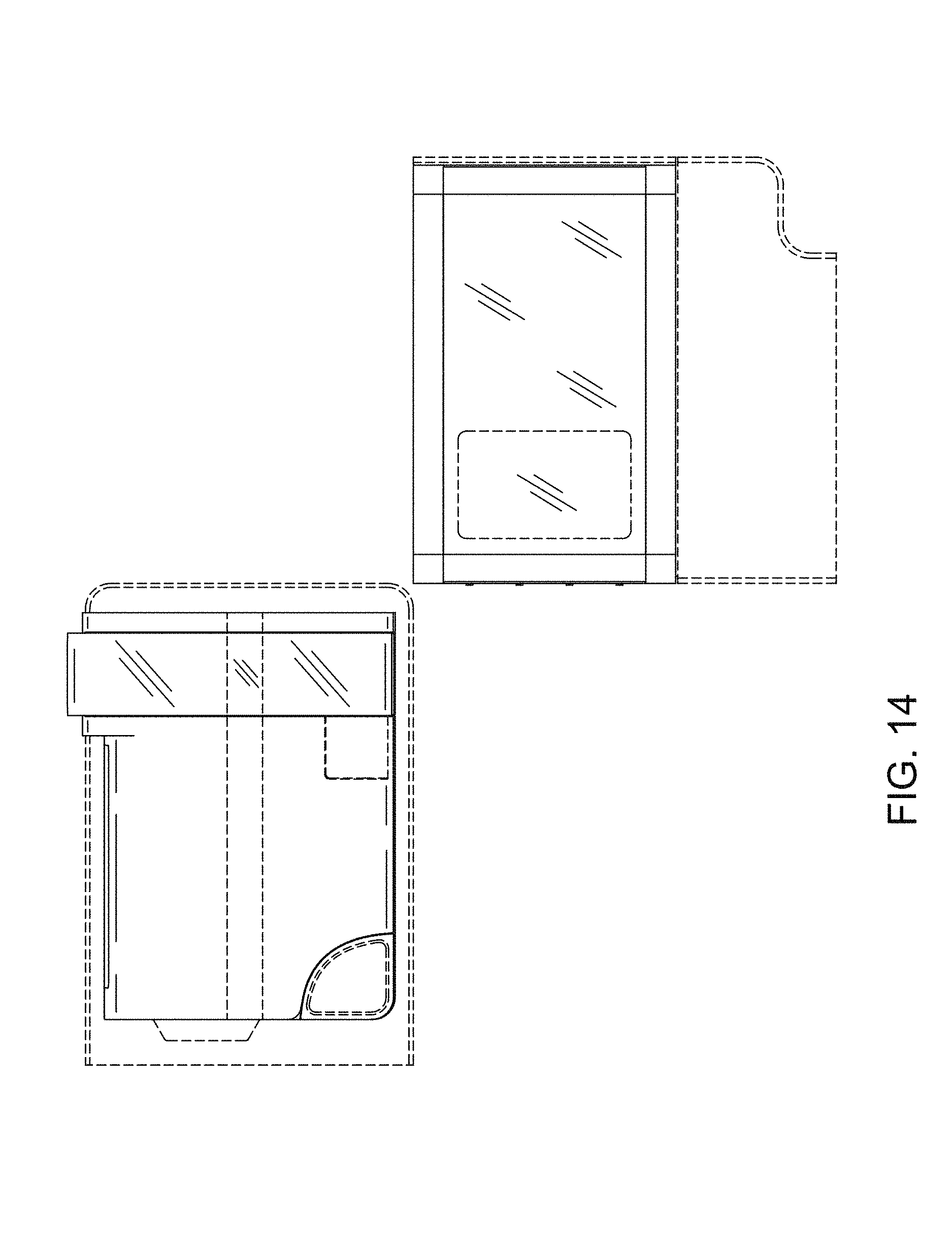
FIG. 14 is a top view of a system including multiple instrument modules and arrangement thereof; and,
FIG. 15 is a bottom view of a system including multiple instrument modules and arrangement thereof.
The broken lines shown in the figures represent portions of the system including multiple instrument modules and arrangement thereof that form no part of the claimed design.
* * * * *
D00000
D00001
D00002
D00003
D00004
D00005
D00006
D00007
D00008
D00009
D00010
D00011
D00012
D00013
D00014
D00015

XML
uspto.report is an independent third-party trademark research tool that is not affiliated, endorsed, or sponsored by the United States Patent and Trademark Office (USPTO) or any other governmental organization. The information provided by uspto.report is based on publicly available data at the time of writing and is intended for informational purposes only.
While we strive to provide accurate and up-to-date information, we do not guarantee the accuracy, completeness, reliability, or suitability of the information displayed on this site. The use of this site is at your own risk. Any reliance you place on such information is therefore strictly at your own risk.
All official trademark data, including owner information, should be verified by visiting the official USPTO website at www.uspto.gov. This site is not intended to replace professional legal advice and should not be used as a substitute for consulting with a legal professional who is knowledgeable about trademark law.