Receptacle
Knight A
U.S. patent number D857,883 [Application Number D/670,399] was granted by the patent office on 2019-08-27 for receptacle. This patent grant is currently assigned to Gen-Probe Incorporated. The grantee listed for this patent is Gen-Probe Incorporated. Invention is credited to Byron J. Knight.


| United States Patent | D857,883 |
| Knight | August 27, 2019 |
Receptacle
Claims
CLAIM The ornamental design for a receptacle, as shown.
| Inventors: | Knight; Byron J. (San Diego, CA) | ||||||||||
|---|---|---|---|---|---|---|---|---|---|---|---|
| Applicant: |
|
||||||||||
| Assignee: | Gen-Probe Incorporated (San
Diego, CA) |
||||||||||
| Family ID: | 50628976 | ||||||||||
| Appl. No.: | D/670,399 | ||||||||||
| Filed: | November 15, 2018 |
Related U.S. Patent Documents
| Application Number | Filing Date | Patent Number | Issue Date | ||
|---|---|---|---|---|---|
| 16127837 | Sep 11, 2018 | ||||
| 14992663 | Jan 11, 2016 | 10159981 | |||
| 14210163 | Feb 2, 2016 | 9248449 | |||
| Current U.S. Class: | D24/121 |
| Current CPC Class: | B65D39/0017 20130101; B65D17/50 20130101; B65D39/0029 20130101; G01N35/0099 20130101; B65D1/34 20130101; G01N35/10 20130101; B01L3/502 20130101; B01L3/5085 20130101; B65D1/0207 20130101; G01N35/1002 20130101; B01L3/527 20130101; C12Q1/686 20130101; B01L3/5082 20130101; B01L3/523 20130101; B01L3/50825 20130101; B65B69/00 20130101; B01L3/50853 20130101; B65D1/36 20130101; G01N35/026 20130101; G01N35/1079 20130101; B01L3/50855 20130101; B01L2200/142 20130101; B01L2200/0689 20130101; B65D2539/003 20130101; B01L2200/026 20130101; B01L2200/16 20130101; Y10T436/11 20150115; B01L2300/046 20130101; B01L2300/048 20130101; B01L2300/047 20130101; B01L2300/0829 20130101; B01L2300/0838 20130101; B01L2200/02 20130101; G01N30/6091 20130101; B01L2200/141 20130101; G01N2035/00287 20130101; B01L2300/044 20130101; B01L2300/0858 20130101; B01L2400/0406 20130101; B01L2300/0851 20130101; B01L2300/042 20130101; B01L2200/0668 20130101; B01L2300/12 20130101; B01L2300/0609 20130101; B01L2300/0832 20130101; B01L2200/025 20130101 |
| Current International Class: | 2402 |
| Field of Search: | ;D24/121,123,224,226 ;604/317-325 |
References Cited [Referenced By]
U.S. Patent Documents
| 3653528 | April 1972 | Wimmer |
| 4338936 | July 1982 | Nelson |
| 5119560 | June 1992 | Noble |
| 5588949 | December 1996 | Taylor |
| 5673790 | October 1997 | Schramm |
| 5785925 | July 1998 | U'Ren |
| 5846489 | December 1998 | Bienhaus et al. |
| 5863791 | January 1999 | Baldszun et al. |
| 5897008 | April 1999 | Hansen |
| D439673 | March 2001 | Brophy |
| 6216340 | April 2001 | Fassbind et al. |
| 6224573 | May 2001 | Yeager |
| 6312886 | November 2001 | Lee et al. |
| 6403037 | June 2002 | Chang et al. |
| 6455325 | September 2002 | Tajima |
| D511214 | November 2005 | Sasano et al. |
| D583058 | December 2008 | Short |
| D583481 | December 2008 | Yamamoto |
| 7550291 | June 2009 | Belz et al. |
| 7691332 | April 2010 | Kacian et al. |
| 7951336 | May 2011 | Tajima |
| 8460620 | June 2013 | Bartfeld et al. |
| D687567 | August 2013 | Jungheim |
| D709624 | July 2014 | Baum |
| D723181 | February 2015 | Kawamura |
| 9381320 | July 2016 | Vincent |
| D762873 | August 2016 | Baum |
| D805636 | December 2017 | Pike |
| D833030 | November 2018 | Sasano |
| 2001/0049134 | December 2001 | Lee et al. |
| 2002/0168299 | November 2002 | Chang et al. |
| 2003/0162285 | August 2003 | Tajima |
| 2005/0123457 | June 2005 | Tajima et al. |
| 2006/0014272 | January 2006 | Tajima et al. |
| 2006/0205064 | September 2006 | Tajima |
| 2008/0072690 | March 2008 | Kacian et al. |
| 2008/0268529 | October 2008 | Furusato et al. |
| 2010/0224632 | September 2010 | Aneas |
| 2010/0264155 | October 2010 | Harder et al. |
| 2013/0318915 | December 2013 | Iskarous et al. |
| 101443123 | May 2009 | CN | |||
| 0 488 769 | Jun 1992 | EP | |||
| 1 508 527 | Feb 2005 | EP | |||
| 2 030 687 | Mar 2009 | EP | |||
| 2004-294428 | Oct 2004 | JP | |||
| 2005-003425 | Jan 2005 | JP | |||
| 2012/074738 | Jun 2012 | WO | |||
| 2012/173919 | Dec 2012 | WO | |||
Other References
|
PCT International Search Report and Written Opinion dated Oct. 15, 2014 issued in International Application No. PCT/US2014/026789. cited by applicant. |
Primary Examiner: Muller; David G
Attorney, Agent or Firm: Rothwell, Figg, Ernst & Manbeck, P.C. Cappellari; Charles B.
Description
FIG. 1 is a side elevational view of the receptacle showing the design with a middle, annular flange having parallel top and bottom surfaces (the design is symmetrical about a center, longitudinal axis thereof, and thus, front, rear, left, and right side elevational views are identical);
FIG. 2 shows a side cross-sectional view thereof along the line 2-2 in FIG. 1;
FIG. 3 shows a top view thereof;
FIG. 4 shows a top perspective view thereof;
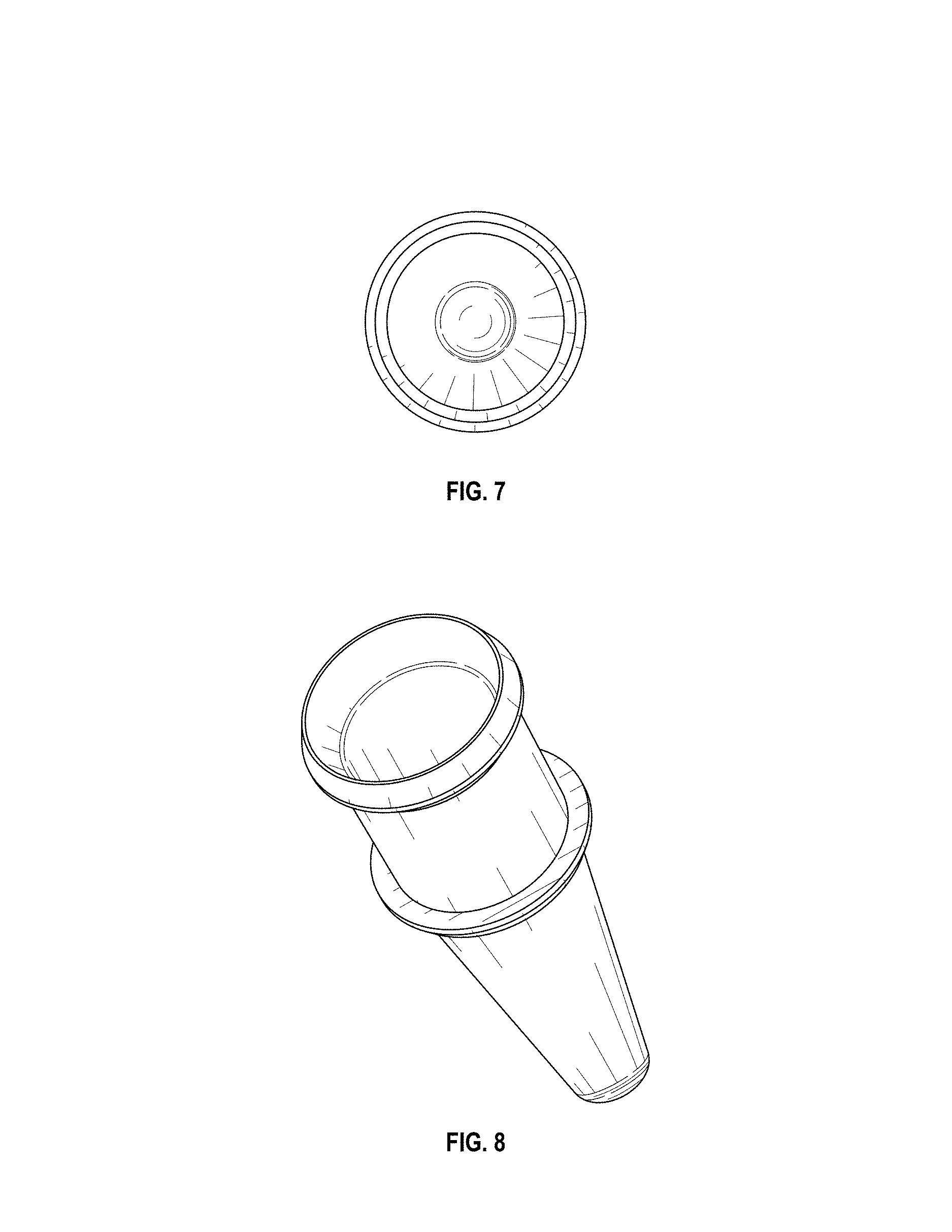
FIG. 5 is a side elevational view of the receptacle showing the design with a middle, annular flange having a bottom surface that is sloped relative to the top surface;
FIG. 6 shows a side cross-sectional view thereof along the line 6-6 in FIG. 5;
FIG. 7 shows a top view of the receptacle of FIG. 5; and,
FIG. 8 shows a top perspective view of the receptacle of FIG. 5.
* * * * *
D00000
D00001
D00002
D00003
D00004
XML
uspto.report is an independent third-party trademark research tool that is not affiliated, endorsed, or sponsored by the United States Patent and Trademark Office (USPTO) or any other governmental organization. The information provided by uspto.report is based on publicly available data at the time of writing and is intended for informational purposes only.
While we strive to provide accurate and up-to-date information, we do not guarantee the accuracy, completeness, reliability, or suitability of the information displayed on this site. The use of this site is at your own risk. Any reliance you place on such information is therefore strictly at your own risk.
All official trademark data, including owner information, should be verified by visiting the official USPTO website at www.uspto.gov. This site is not intended to replace professional legal advice and should not be used as a substitute for consulting with a legal professional who is knowledgeable about trademark law.