Cart
Sherman , et al. A
U.S. patent number D856,622 [Application Number D/621,026] was granted by the patent office on 2019-08-13 for cart. This patent grant is currently assigned to ZIBRA, LLC. The grantee listed for this patent is ZIBRA, LLC. Invention is credited to William Lane Ball, Brent Mitchell Beggs, Michael Milton Sherman.


| United States Patent | D856,622 |
| Sherman , et al. | August 13, 2019 |
Cart
Claims
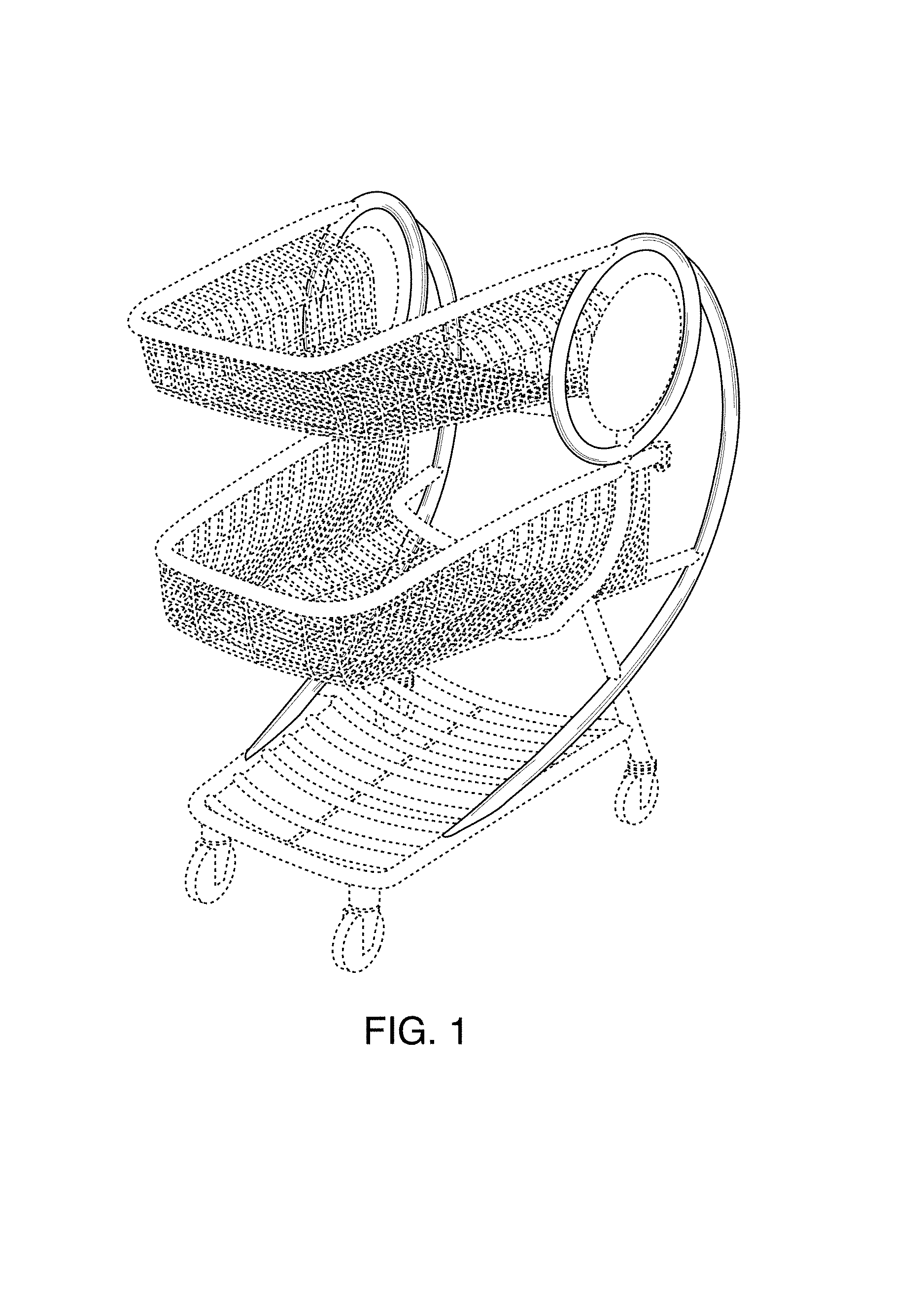
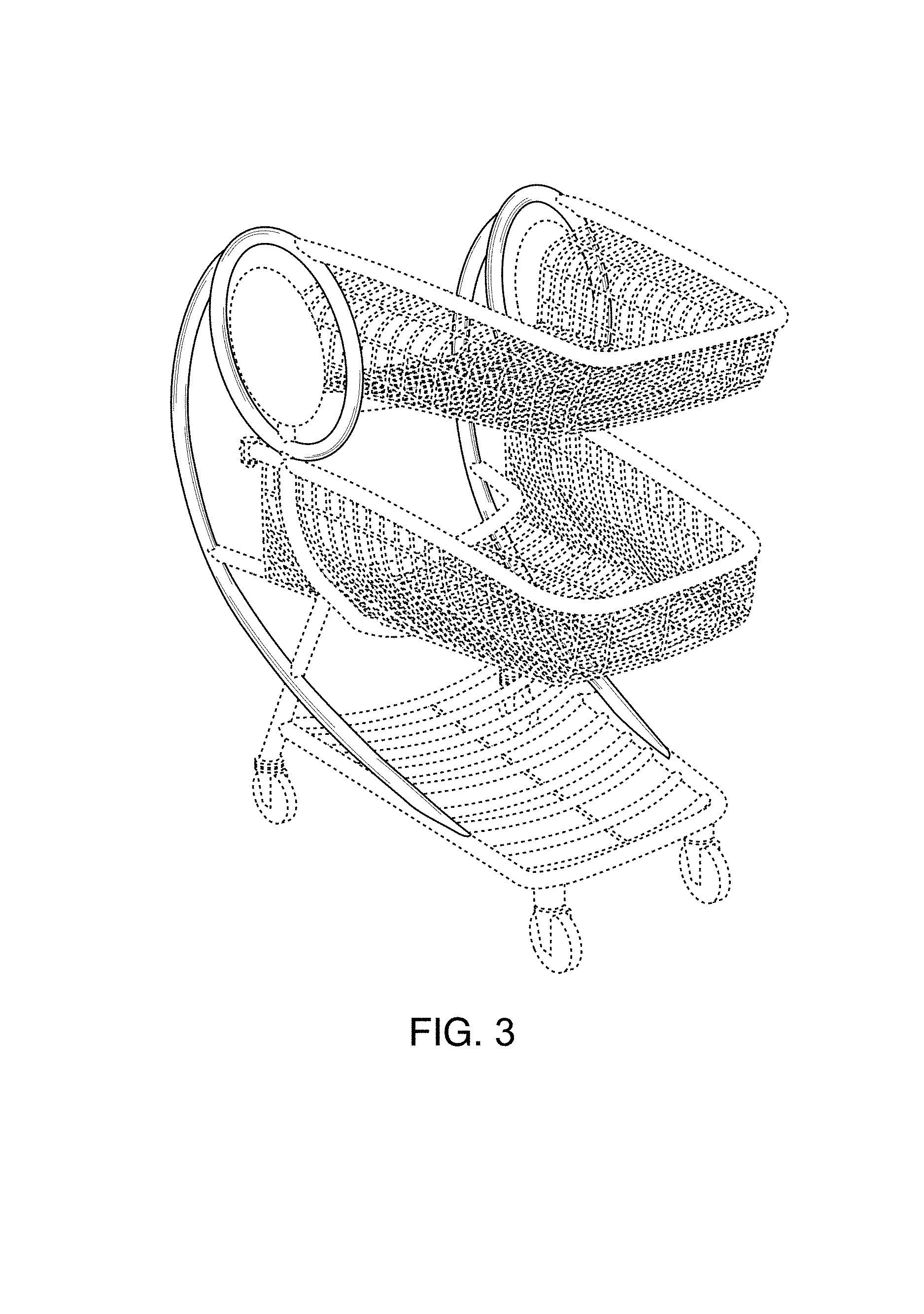
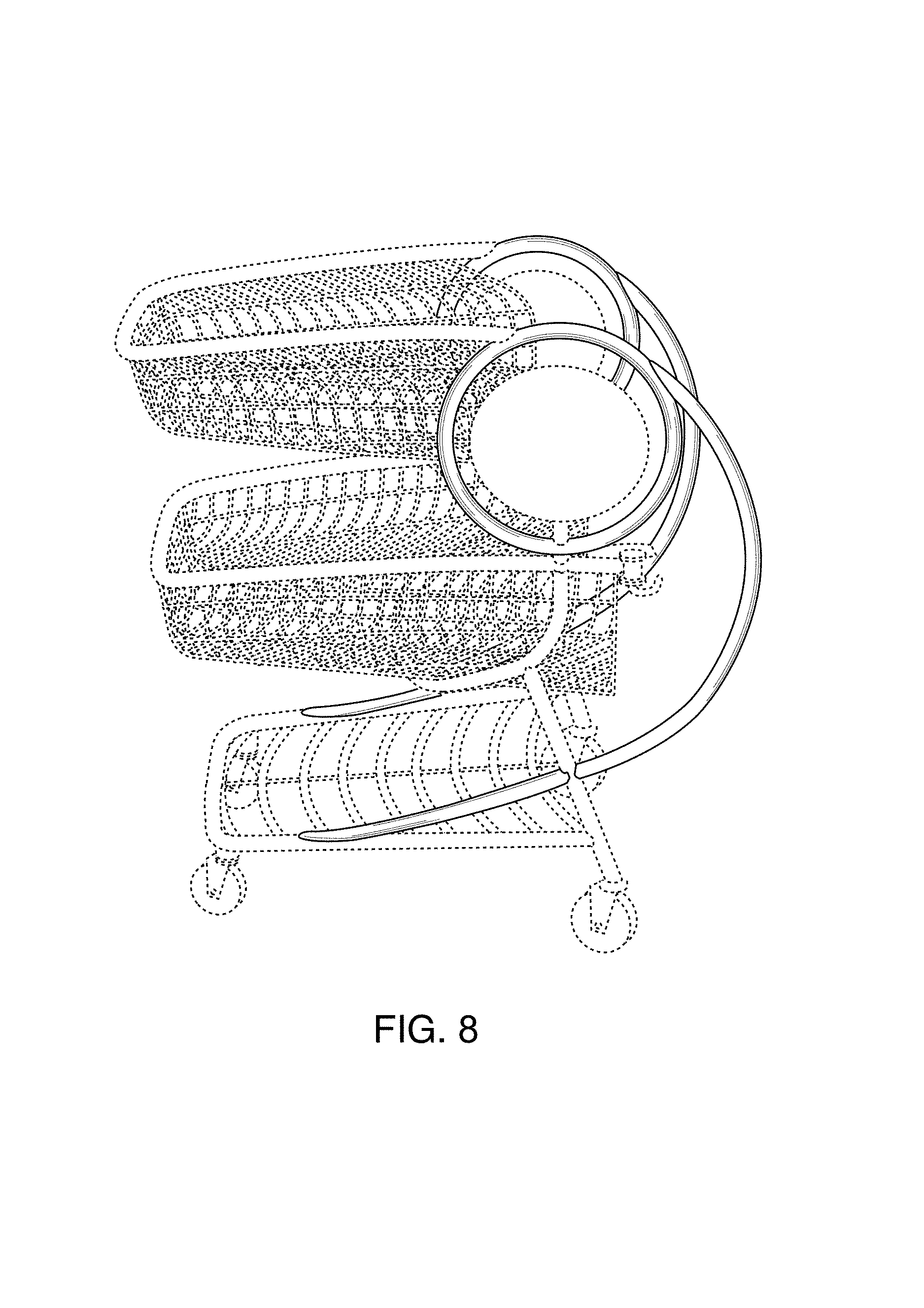
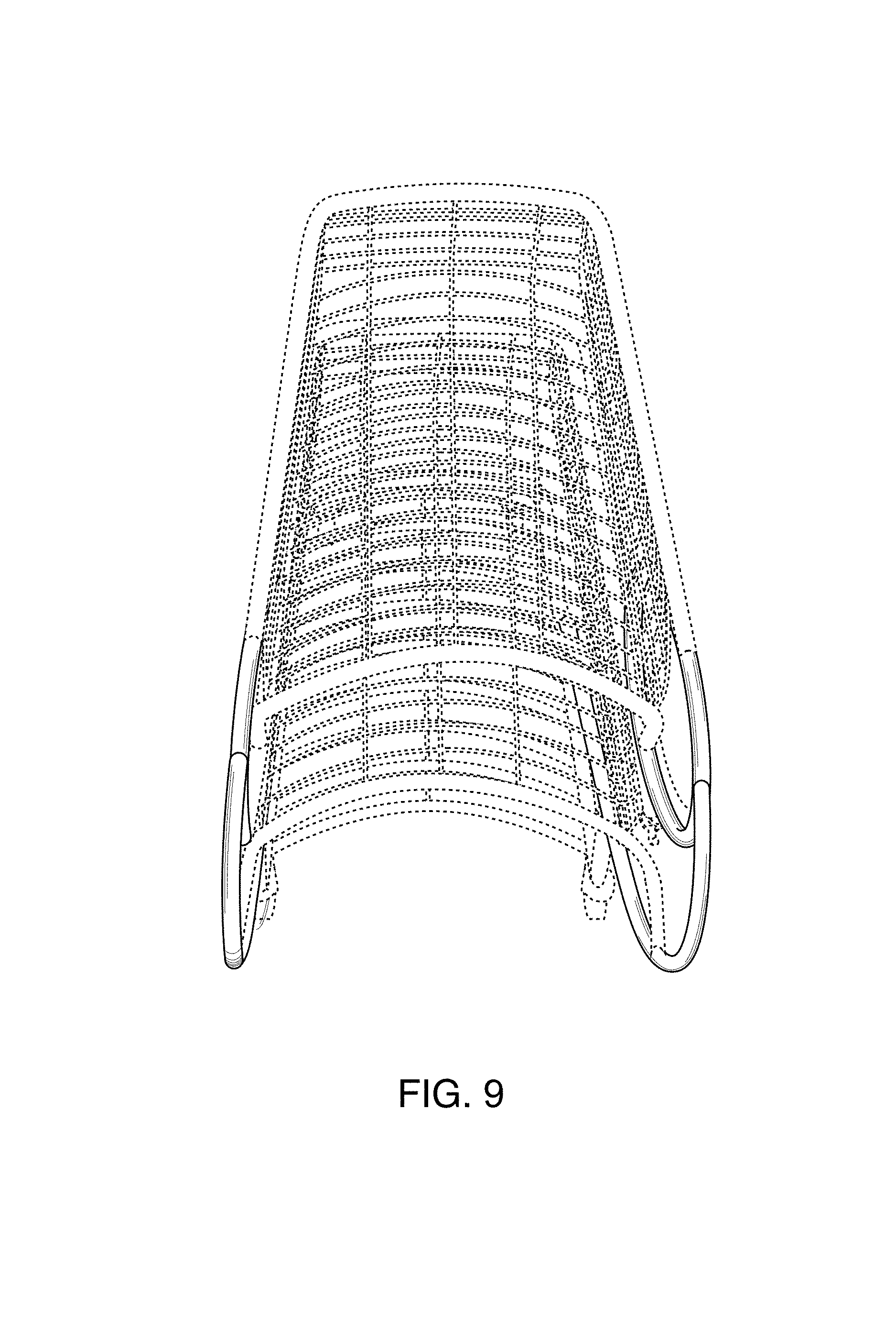
CLAIM The ornamental design for a cart, as shown and described.
| Inventors: | Sherman; Michael Milton (Mooresville, NC), Ball; William Lane (Statesville, NC), Beggs; Brent Mitchell (North Richland Hills, TX) | ||||||||||
|---|---|---|---|---|---|---|---|---|---|---|---|
| Applicant: |
|
||||||||||
| Assignee: | ZIBRA, LLC (Mooresville,
NC) |
||||||||||
| Appl. No.: | D/621,026 | ||||||||||
| Filed: | October 3, 2017 |
Related U.S. Patent Documents
| Application Number | Filing Date | Patent Number | Issue Date | ||
|---|---|---|---|---|---|
| 29550895 | Jan 7, 2016 | D800408 | |||
| Current U.S. Class: | D34/27 |
| Current International Class: | 1202 |
| Field of Search: | ;D34/12-26,27 |
References Cited [Referenced By]
U.S. Patent Documents
| D633269 | February 2011 | Walter |
| D749286 | February 2016 | Sherman |
| D790147 | June 2017 | Sherman |
| D802867 | November 2017 | Sherman |
| D802868 | November 2017 | Sherman |
| D802869 | November 2017 | Sherman |
| D802870 | November 2017 | Sherman |
| 2016/0257329 | September 2016 | Sherman |
Attorney, Agent or Firm: Tillman; Chad D Tillman Wright, PLLC
Description
FIG. 1 is a perspective view of a front left corner of a cart showing our new design.
FIG. 2 is a perspective view of the front of the cart of FIG. 1 following rotation in a counterclockwise direction of the cart from the view of FIG. 1.
FIG. 3 is a perspective view of the front right corner of the cart of FIG. 1 following continued rotation of the cart from the view of FIG. 2.
FIG. 4 is a perspective view of the right side of the cart of FIG. 1 following continued rotation of the cart from the view of FIG. 3.
FIG. 5 is a perspective view of the back right corner of the cart of FIG. 1 following continued rotation of the cart from the view of FIG. 4.
FIG. 6 is a perspective view of the back of the cart of FIG. 1 following continued rotation of the cart from the view of FIG. 5.
FIG. 7 is a perspective view of the back left corner of the cart of FIG. 1 following continued rotation of the cart from the view of FIG. 6.
FIG. 8 is a perspective view of the left side of the cart of FIG. 1 following continued rotation of the cart from the view of FIG. 7; and,
FIG. 9 is a perspective view of the top of the cart of FIG. 1.
The broken lines in the figures are included for the purpose of illustrating portions of the cart and form no part of the claimed design.
* * * * *
D00000
D00001
D00002
D00003
D00004
D00005
D00006
D00007
D00008
D00009
XML
uspto.report is an independent third-party trademark research tool that is not affiliated, endorsed, or sponsored by the United States Patent and Trademark Office (USPTO) or any other governmental organization. The information provided by uspto.report is based on publicly available data at the time of writing and is intended for informational purposes only.
While we strive to provide accurate and up-to-date information, we do not guarantee the accuracy, completeness, reliability, or suitability of the information displayed on this site. The use of this site is at your own risk. Any reliance you place on such information is therefore strictly at your own risk.
All official trademark data, including owner information, should be verified by visiting the official USPTO website at www.uspto.gov. This site is not intended to replace professional legal advice and should not be used as a substitute for consulting with a legal professional who is knowledgeable about trademark law.