Eyeglass frame
Stipancik , et al.
U.S. patent number D855,691 [Application Number D/629,792] was granted by the patent office on 2019-08-06 for eyeglass frame. This patent grant is currently assigned to North Inc.. The grantee listed for this patent is Thalmic Labs Inc.. Invention is credited to Joshua Moore, Marie Stipancik.


View All Diagrams
| United States Patent | D855,691 |
| Stipancik , et al. | August 6, 2019 |
Eyeglass frame
Claims
CLAIM The ornamental design for an eyeglass frame, as shown and described.
| Inventors: | Stipancik; Marie (Waterloo, CA), Moore; Joshua (Elora, CA) | ||||||||||
|---|---|---|---|---|---|---|---|---|---|---|---|
| Applicant: |
|
||||||||||
| Assignee: | North Inc. (Kitchener, Ontario,
CA) |
||||||||||
| Appl. No.: | D/629,792 | ||||||||||
| Filed: | December 15, 2017 |
Related U.S. Patent Documents
| Application Number | Filing Date | Patent Number | Issue Date | ||
|---|---|---|---|---|---|
| 29581390 | Oct 18, 2016 | ||||
| Current U.S. Class: | D16/334 |
| Current International Class: | 1606 |
| Field of Search: | ;D16/101,300-342,900 ;D29/109-110 ;D21/483,659-661 ;D14/372 ;351/41,44,45-48,51-52,62,158,92,103-123,140-153,63,59 ;2/13,15,426-432,447-449,441,434-437 |
References Cited [Referenced By]
U.S. Patent Documents
| D422617 | April 2000 | Simioni |
| 7607775 | October 2009 | Hermanson et al. |
| D628616 | December 2010 | Yuan |
| D633939 | March 2011 | Puentes |
| D634771 | March 2011 | Fuchs |
| D640314 | June 2011 | Yang |
| D649177 | November 2011 | Cho |
| D664183 | July 2012 | Stepan et al. |
| D665838 | August 2012 | Kim et al. |
| D667482 | September 2012 | Healy |
| D669522 | October 2012 | Klinar |
| D669523 | October 2012 | Wakata |
| D671590 | November 2012 | Klinar |
| D682343 | May 2013 | Waters |
| D685019 | June 2013 | Li |
| D687087 | July 2013 | Iurilli |
| D690761 | October 2013 | He et al. |
| D692941 | November 2013 | Klinar |
| D695333 | December 2013 | Farnam |
| D701555 | March 2014 | Markovitz |
| D704248 | May 2014 | DiChiara |
| D719568 | December 2014 | Heinrich |
| D719570 | December 2014 | Heinrich |
| D723093 | February 2015 | Li |
| D724647 | March 2015 | Rohrbach |
| D738373 | September 2015 | Davies |
| D747759 | January 2016 | Ho |
| D758476 | June 2016 | Ho |
| D760313 | June 2016 | Ho |
| D763344 | August 2016 | Roy et al. |
| D766895 | September 2016 | Choi |
| D768627 | October 2016 | Rochat |
| D771735 | November 2016 | Lee |
| D780828 | March 2017 | Bonaventura |
| D780829 | March 2017 | Bonaventura |
| 2006/0132705 | June 2006 | Li |
Assistant Examiner: Paul; Sanjeev
Attorney, Agent or Firm: Cozen O'Connor
Description
FIG. 1 is a top isometric view of an eyeglass frame showing an embodiment of our new design comprising eyeglass frame arms.
FIG. 2 is a bottom isometric view thereof.
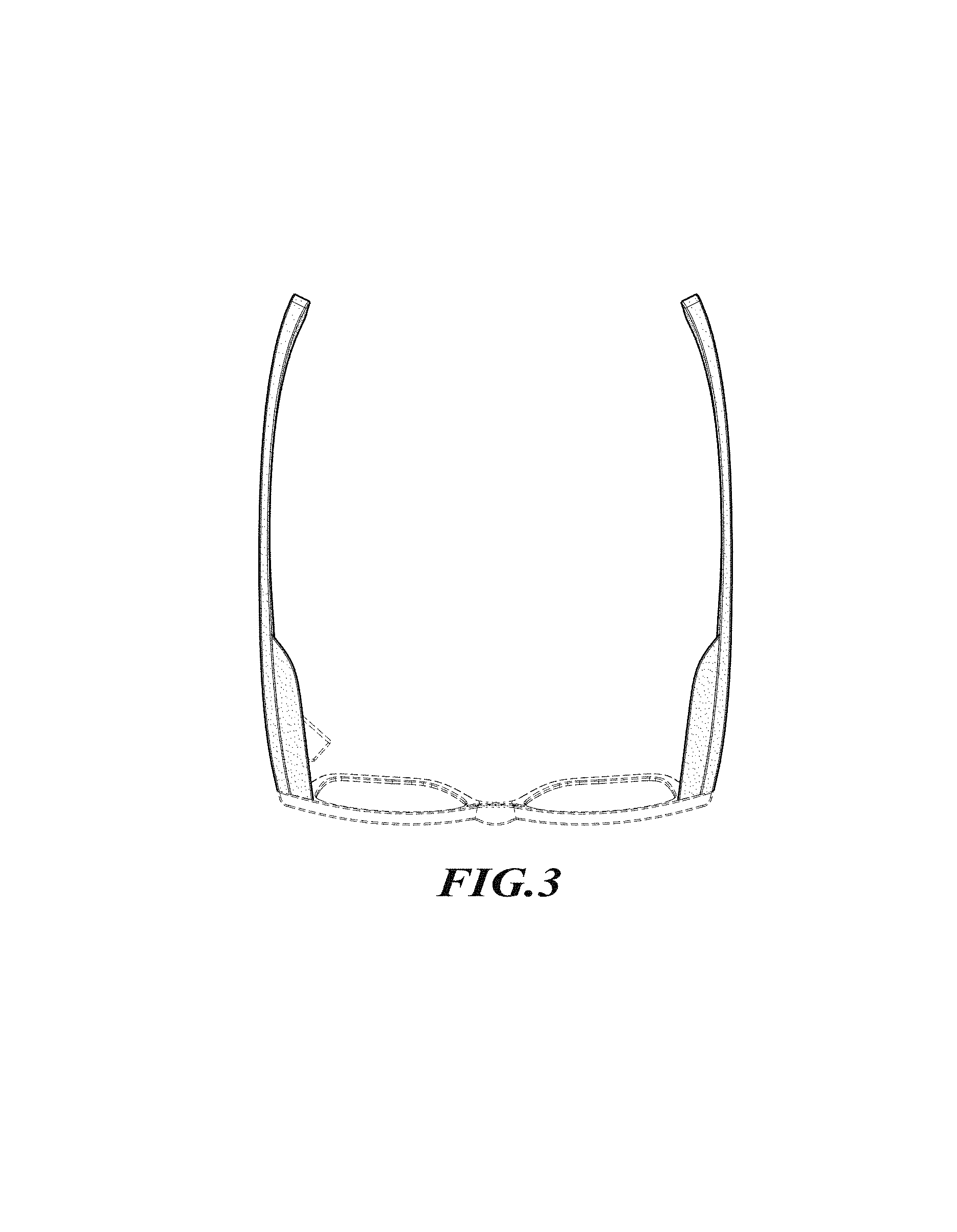
FIG. 3 is a top plan view thereof.
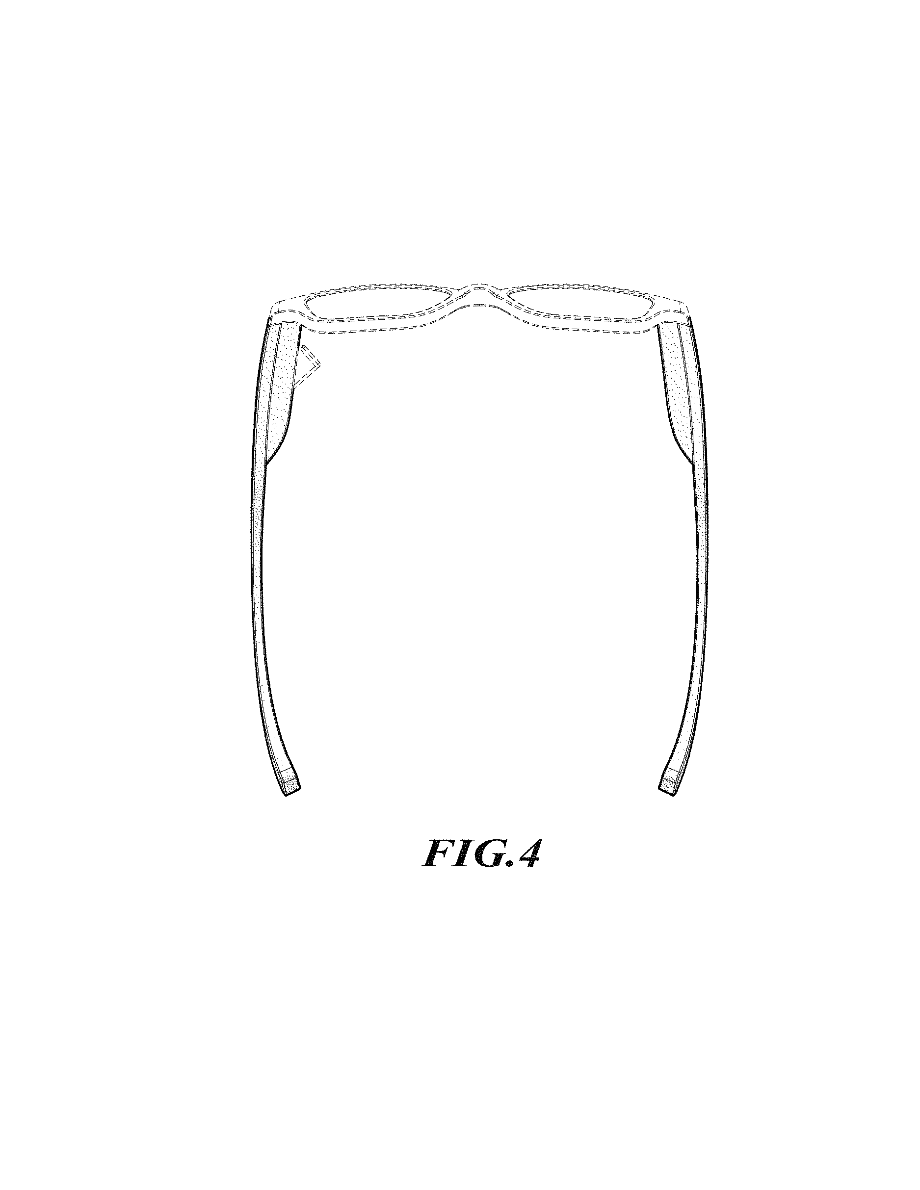
FIG. 4 is a bottom plan view thereof.
FIG. 5 is a left side elevational view thereof.
FIG. 6 is a right side elevational view thereof.
FIG. 7 is a front elevational view thereof.
FIG. 8 is a rear elevational view thereof.
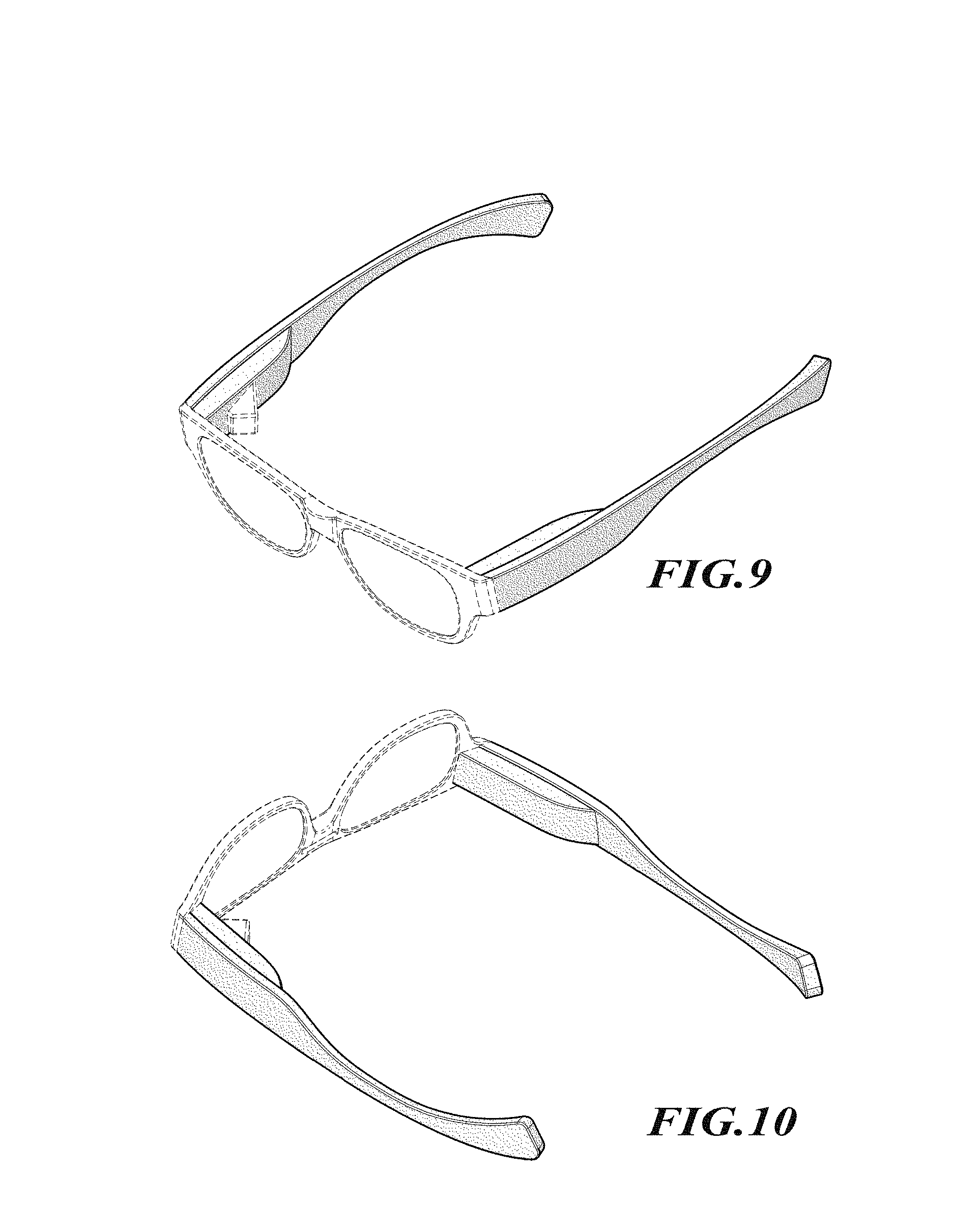
FIG. 9 is a top isometric view of the eyeglass frame according to the embodiment of FIGS. 1-8 but with different environmental structure to illustrate the versatility of the new design.
FIG. 10 is a bottom isometric view thereof.
FIG. 11 is a top plan view thereof.
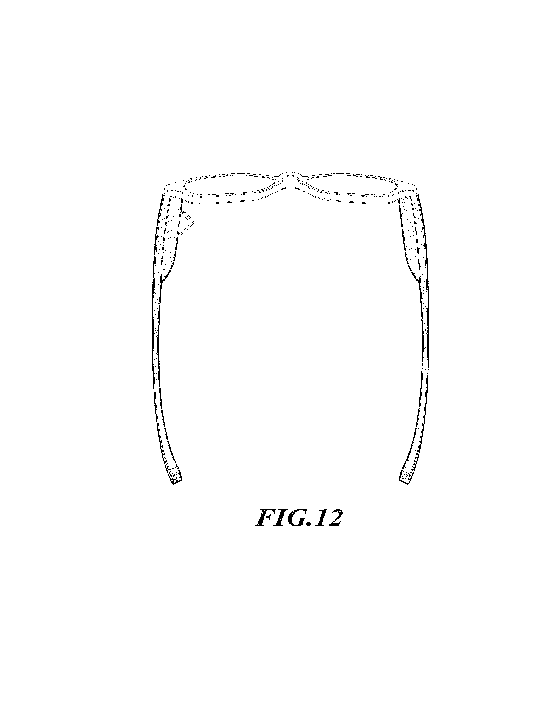
FIG. 12 is a bottom plan view thereof.
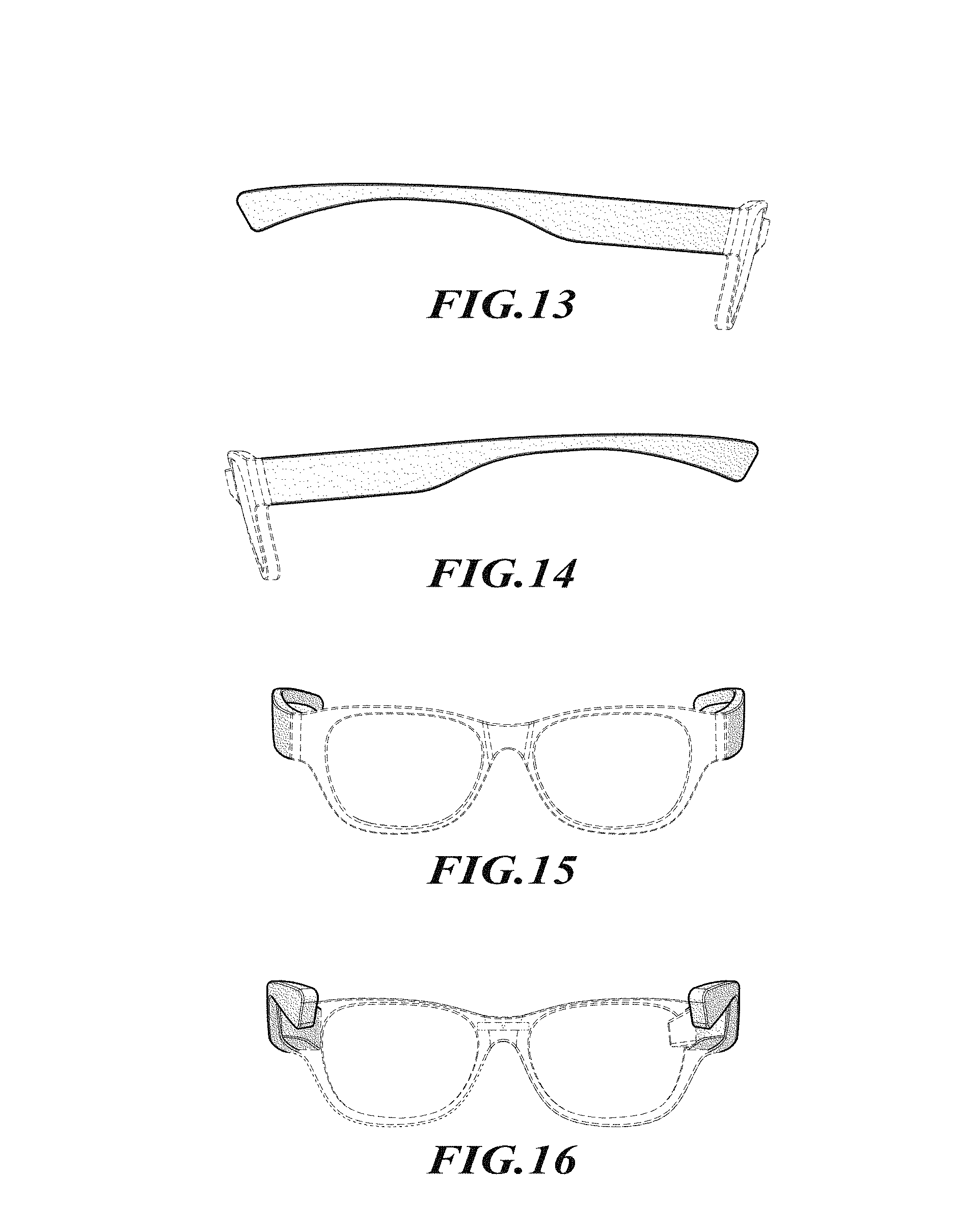
FIG. 13 is a left side elevational view thereof.
FIG. 14 is a right side elevational view thereof.
FIG. 15 is a front elevational view thereof.
FIG. 16 is a rear elevational view thereof.
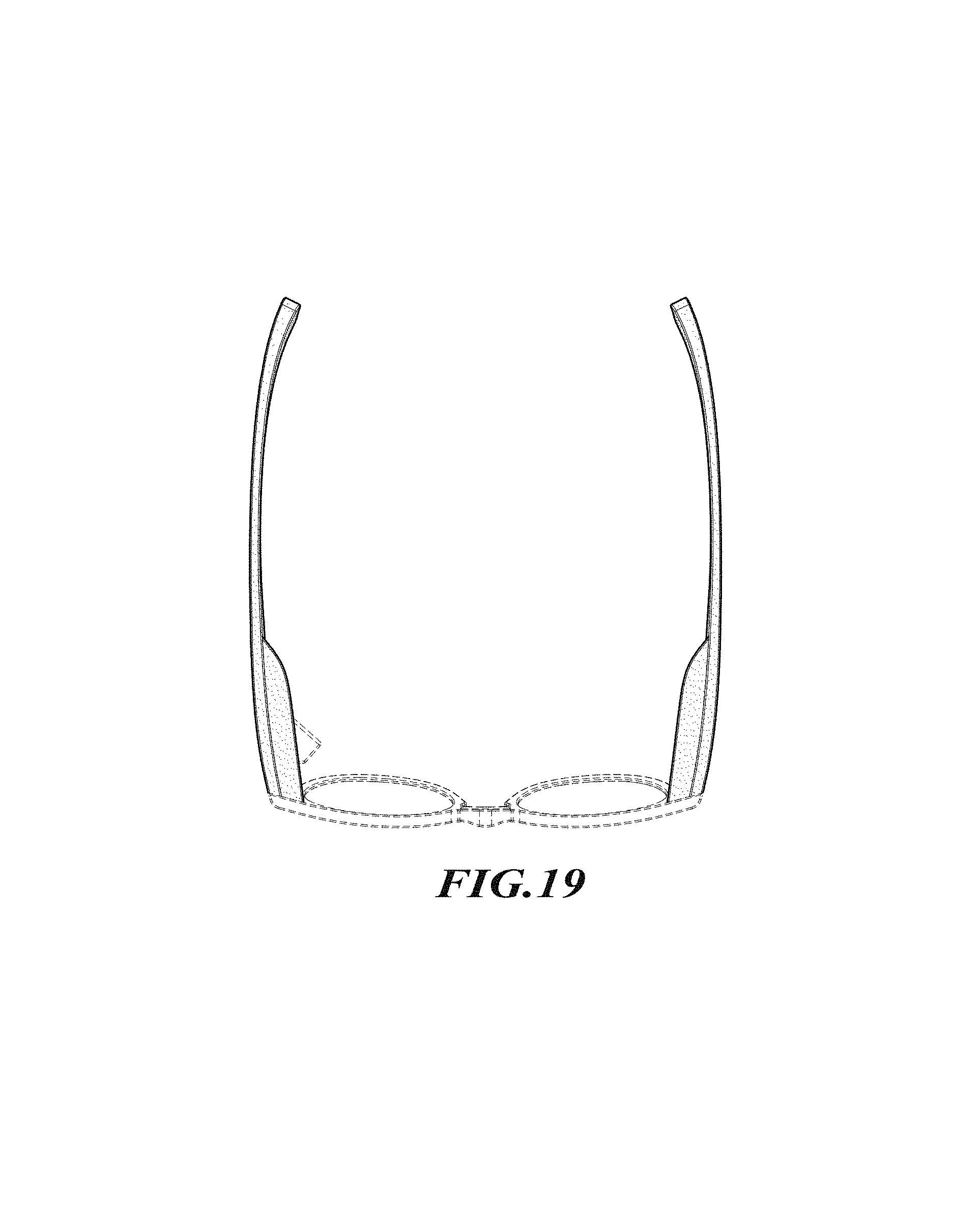
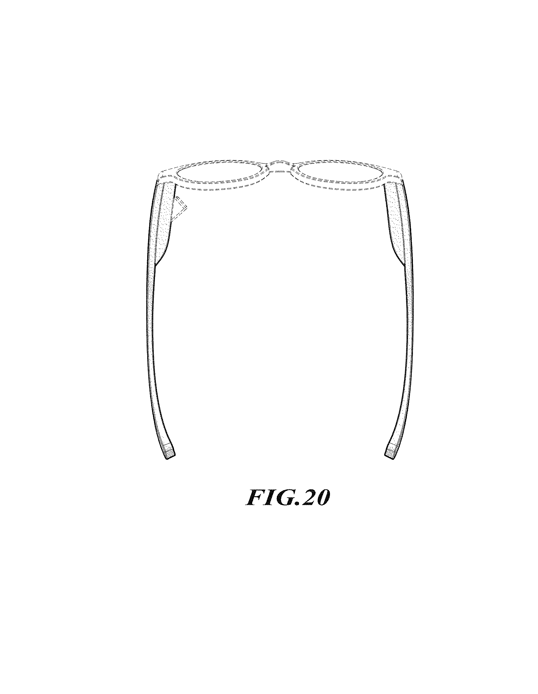
FIG. 17 is a top isometric view of the eyeglass frame according to the embodiment of FIGS. 1-8 and FIGS. 9-17 but with different environmental structure to further illustrate the versatility of the new design.
FIG. 18 is a bottom isometric view thereof.
FIG. 19 is a top plan view thereof.
FIG. 20 is a bottom plan view thereof.
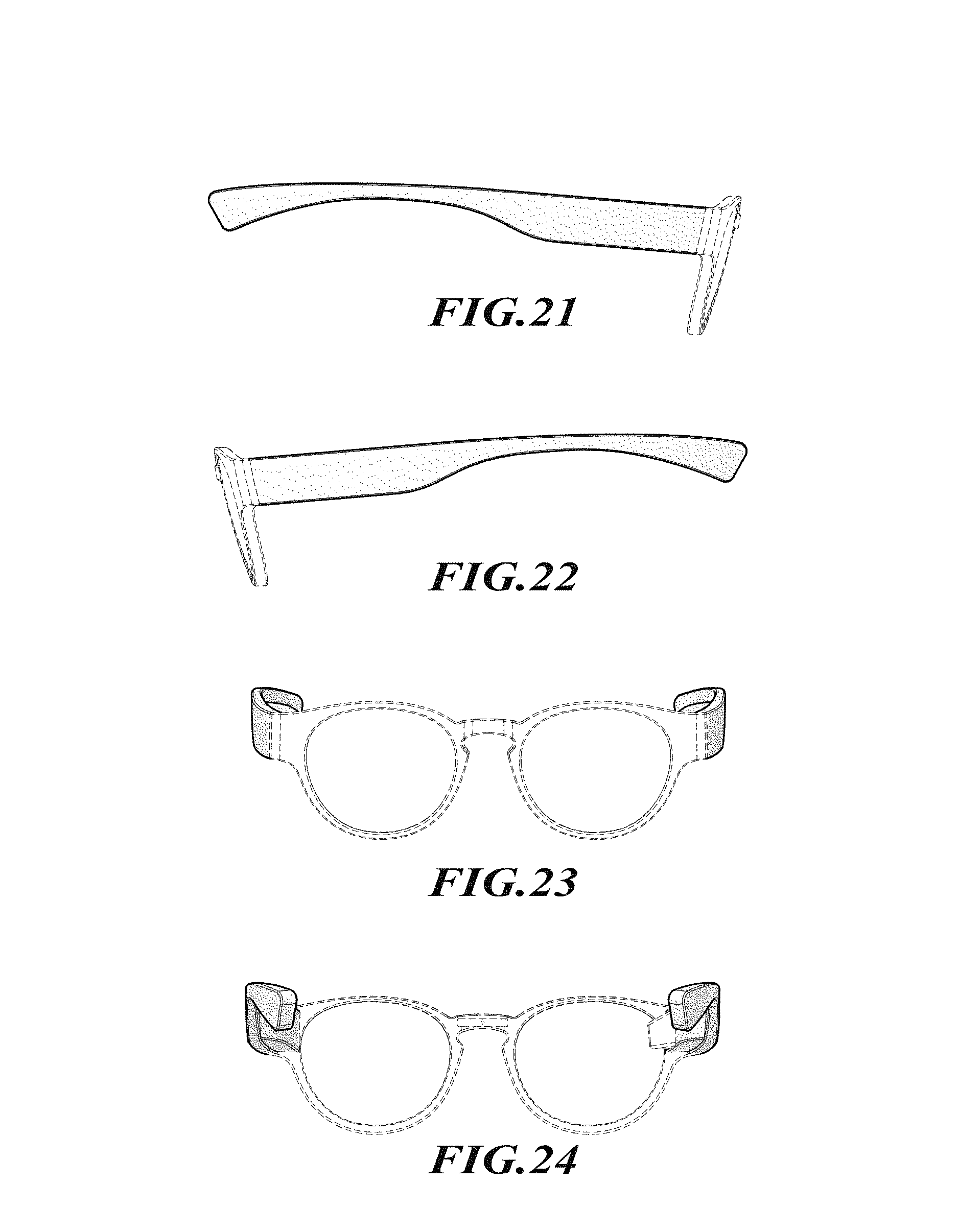
FIG. 21 is a left side elevational view thereof.
FIG. 22 is a right side elevational view thereof.
FIG. 23 is a front elevational view thereof; and,
FIG. 24 is a rear elevational view thereof.
Stippling and tangency lines in the drawings represent the three-dimensional contours of the design, and are not intended to indicate surface decoration. The broken lines in the drawings are included for the purpose of illustrating unclaimed portions of the eyeglass frame that form no part of the claimed design.
* * * * *
D00000
D00001
D00002
D00003
D00004
D00005
D00006
D00007
D00008
D00009
D00010
D00011
D00012
XML
uspto.report is an independent third-party trademark research tool that is not affiliated, endorsed, or sponsored by the United States Patent and Trademark Office (USPTO) or any other governmental organization. The information provided by uspto.report is based on publicly available data at the time of writing and is intended for informational purposes only.
While we strive to provide accurate and up-to-date information, we do not guarantee the accuracy, completeness, reliability, or suitability of the information displayed on this site. The use of this site is at your own risk. Any reliance you place on such information is therefore strictly at your own risk.
All official trademark data, including owner information, should be verified by visiting the official USPTO website at www.uspto.gov. This site is not intended to replace professional legal advice and should not be used as a substitute for consulting with a legal professional who is knowledgeable about trademark law.