Patient table
Doerrfuss , et al.
U.S. patent number D855,189 [Application Number D/595,288] was granted by the patent office on 2019-07-30 for patient table. This patent grant is currently assigned to Siemens Healthcare GmbH. The grantee listed for this patent is Siemens Healthcare GmbH. Invention is credited to Bruno Doerrfuss, Florian Hilbig, Daniel Lerch, Selma Osmanlic, Lei Pan, Carsten Thierfelder.


| United States Patent | D855,189 |
| Doerrfuss , et al. | July 30, 2019 |
Patient table
Claims
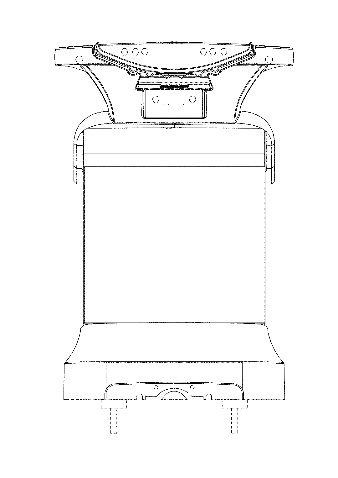
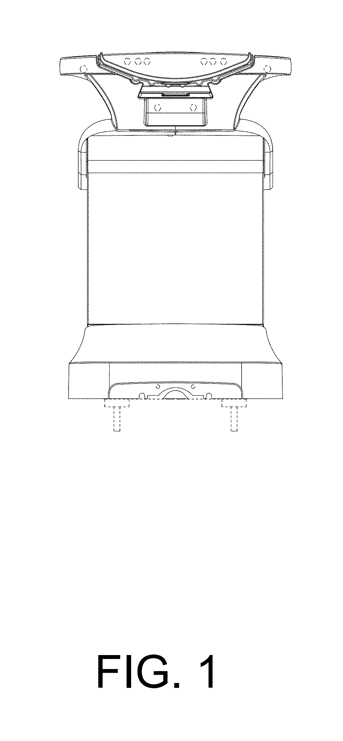
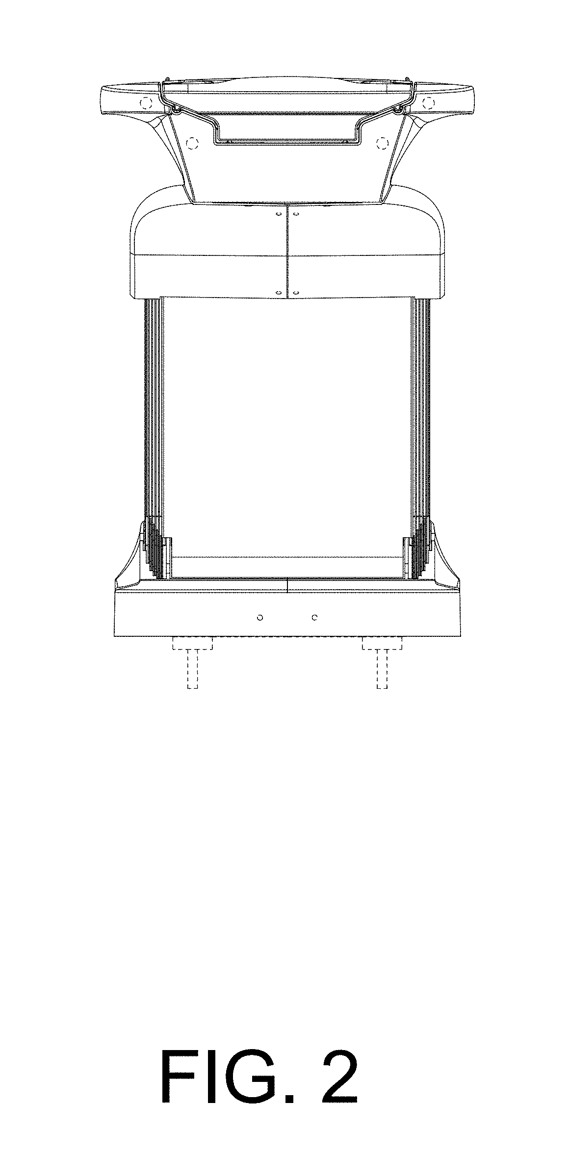
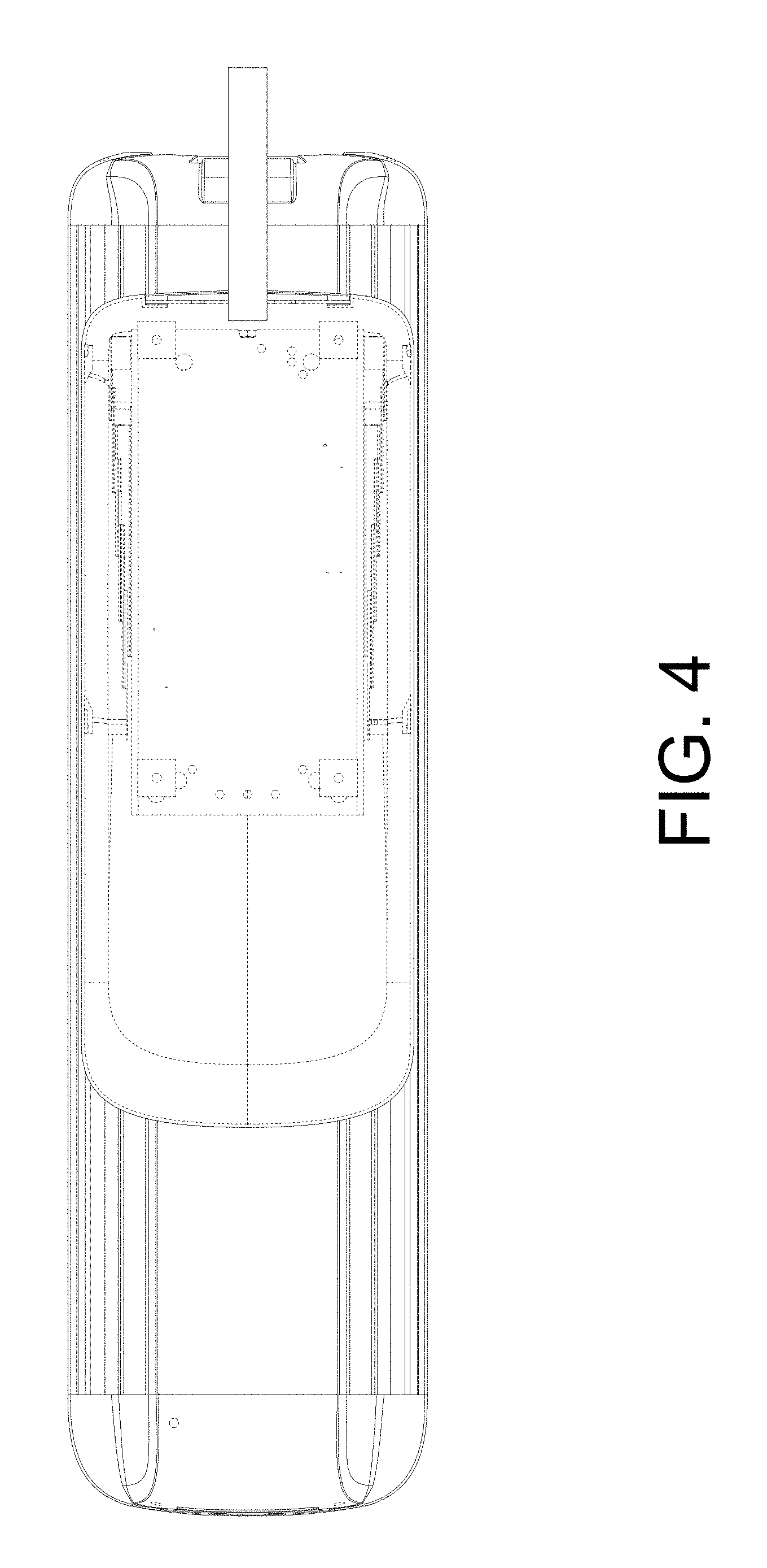
CLAIM The ornamental design for a patient table, as shown and described.
| Inventors: | Doerrfuss; Bruno (Neunkirchen, DE), Hilbig; Florian (Munich, DE), Lerch; Daniel (Weilersbach, DE), Osmanlic; Selma (Forchheim, DE), Pan; Lei (Shanghai, CN), Thierfelder; Carsten (Pinzberg, DE) | ||||||||||
|---|---|---|---|---|---|---|---|---|---|---|---|
| Applicant: |
|
||||||||||
| Assignee: | Siemens Healthcare GmbH
(Erlangen, DE) |
||||||||||
| Appl. No.: | D/595,288 | ||||||||||
| Filed: | February 27, 2017 |
Foreign Application Priority Data
| Aug 30, 2016 [EM] | 001452148 | |||
| Current U.S. Class: | D24/183 |
| Current International Class: | 2402 |
| Field of Search: | ;D24/159,183,184,185,186,187 |
References Cited [Referenced By]
U.S. Patent Documents
| 3281141 | October 1966 | Smiley |
| 3452977 | July 1969 | Ryman |
| D221910 | September 1971 | Brendgord |
| 3868103 | February 1975 | Pageot |
| 3982741 | September 1976 | Mitchell |
| 4195829 | April 1980 | Reser |
| D260172 | August 1981 | Kyle |
| D324103 | February 1992 | Masuda et al. |
| D344802 | March 1994 | Kuck |
| 5528782 | June 1996 | Pfeuffer |
| 6038718 | March 2000 | Pennington |
| D453968 | February 2002 | Zachrisson |
| D462445 | September 2002 | Barde |
| 6754923 | June 2004 | Borders |
| D518894 | April 2006 | Kirn |
| D527459 | August 2006 | Gireesh |
| D552389 | October 2007 | Papiernik |
| D553246 | October 2007 | Banryu |
| 7761941 | July 2010 | Loser |
| D630330 | January 2011 | Baba |
| D681208 | April 2013 | Ninomiya et al. |
| D701605 | March 2014 | Ohmukai |
| D726319 | April 2015 | Sul |
| D727509 | April 2015 | Tan |
| D731068 | June 2015 | Moon et al. |
| D735864 | August 2015 | Doerre |
| D736390 | August 2015 | Kim |
| D736934 | August 2015 | Kim |
| D743555 | November 2015 | Hasebe |
| 9233042 | January 2016 | Freude |
| D748804 | February 2016 | Eenboom et al. |
| D774195 | December 2016 | Ramos |
| D820459 | June 2018 | Eenboom |
| D829913 | October 2018 | Kitayama |
| 2004/0148703 | August 2004 | Doering |
| 2005/0125896 | June 2005 | Cavalier et al. |
| 2007/0107122 | May 2007 | Georgi |
| 2009/0144902 | June 2009 | Baumann |
| 2011/0296613 | December 2011 | Farmbauer |
| 2016/0174914 | June 2016 | Lerch et al. |
| 2016/0287461 | October 2016 | Naughton |
Other References
|
Siemens Somatom Force designaffairs. [online] Published Oct. 23, 2015. Retrieved Jun. 5, 2018 from URL:https://www.designaffairs.com/siemens-somatom-force/. cited by applicant . Siemens Healthineers introduces new platform for computed tomography at ECR 2017. [online] Published Mar. 3, 2017. Retrieved Jun. 5, 2018 from URL: https://www.news-medical.net/news/20170303/ Siemens-Heal th i neers-i ntrod uces-new-platform-for -computed-tomography-at-EC R-2017 .aspx. cited by applicant. |
Primary Examiner: Simmons; Ian
Assistant Examiner: Lawrence; Samantha Q
Attorney, Agent or Firm: Schiff Hardin LLP
Description
FIG. 1 is a front elevational view of a patient table showing our new design;
FIG. 2 is a back elevational view thereof;
FIG. 3 is a top plan view thereof;
FIG. 4 is a bottom plan view thereof;
FIG. 5 is a side elevational view of the right side thereof;
FIG. 6 is a side elevational view of the left side thereof; and
FIG. 7 is a perspective view taken generally from the top, front, right-hand side thereof; and,
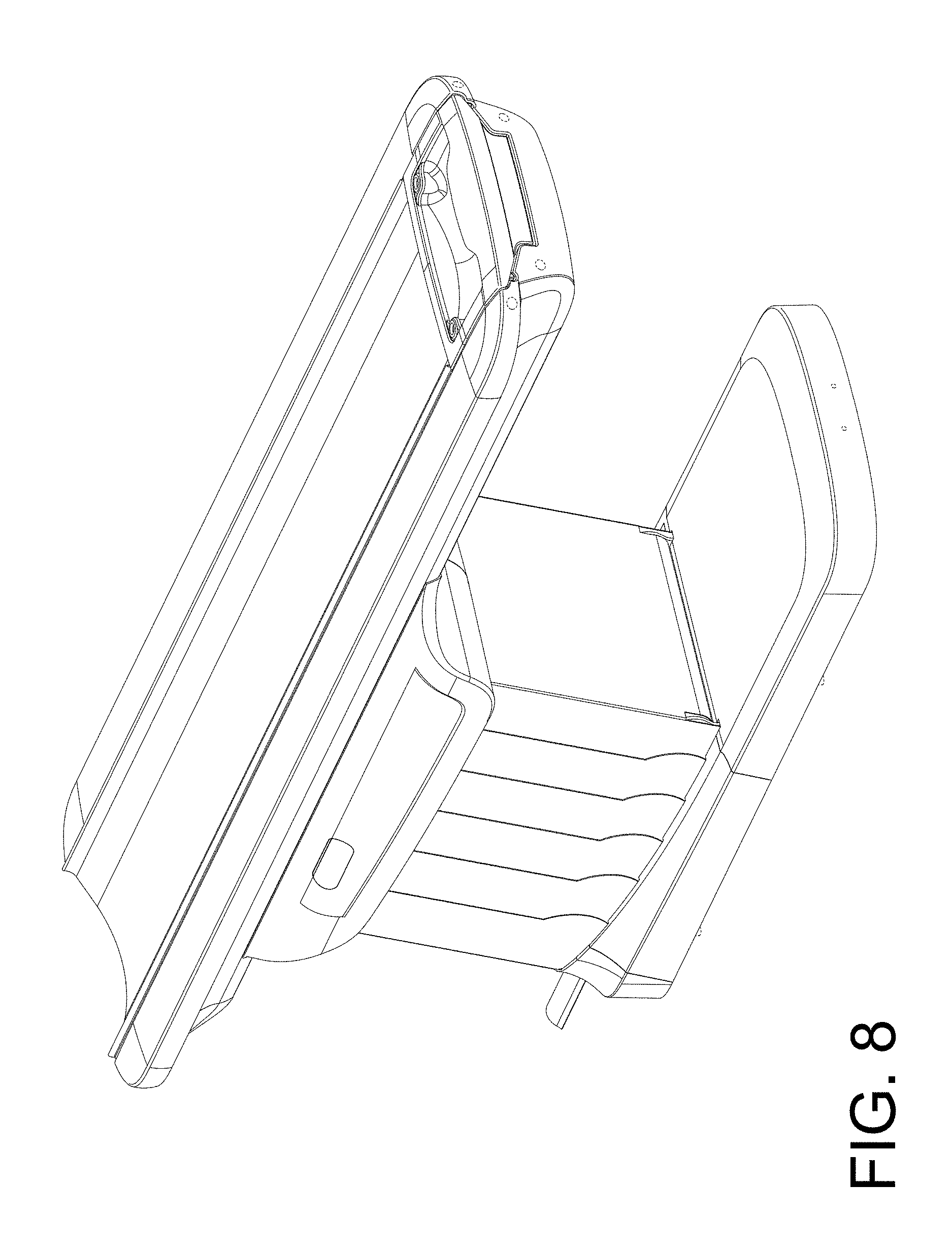
FIG. 8 is a perspective view taken generally from the top, back, right-hand side thereof.
The broken lines are included for the purpose of illustrating portions of the patient table that form no part of the claimed design.
* * * * *
References
D00000
D00001
D00002
D00003
D00004
D00005
D00006
D00007
D00008
XML
uspto.report is an independent third-party trademark research tool that is not affiliated, endorsed, or sponsored by the United States Patent and Trademark Office (USPTO) or any other governmental organization. The information provided by uspto.report is based on publicly available data at the time of writing and is intended for informational purposes only.
While we strive to provide accurate and up-to-date information, we do not guarantee the accuracy, completeness, reliability, or suitability of the information displayed on this site. The use of this site is at your own risk. Any reliance you place on such information is therefore strictly at your own risk.
All official trademark data, including owner information, should be verified by visiting the official USPTO website at www.uspto.gov. This site is not intended to replace professional legal advice and should not be used as a substitute for consulting with a legal professional who is knowledgeable about trademark law.