Networking device
Wild July 16, 2
U.S. patent number D853,996 [Application Number D/577,146] was granted by the patent office on 2019-07-16 for networking device. This patent grant is currently assigned to Tridonic GMBH & Co., KG. The grantee listed for this patent is TRIDONIC GMBH & CO. KG. Invention is credited to Emanuel Wild.


| United States Patent | D853,996 |
| Wild | July 16, 2019 |
Networking device
Claims
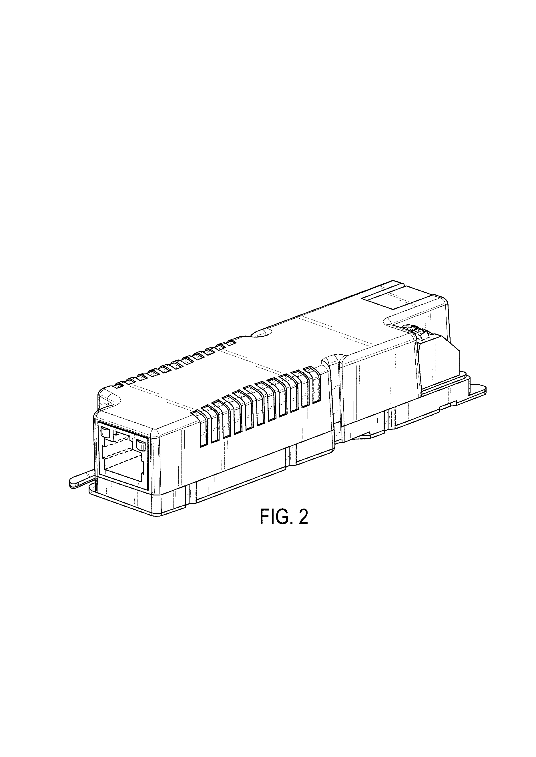
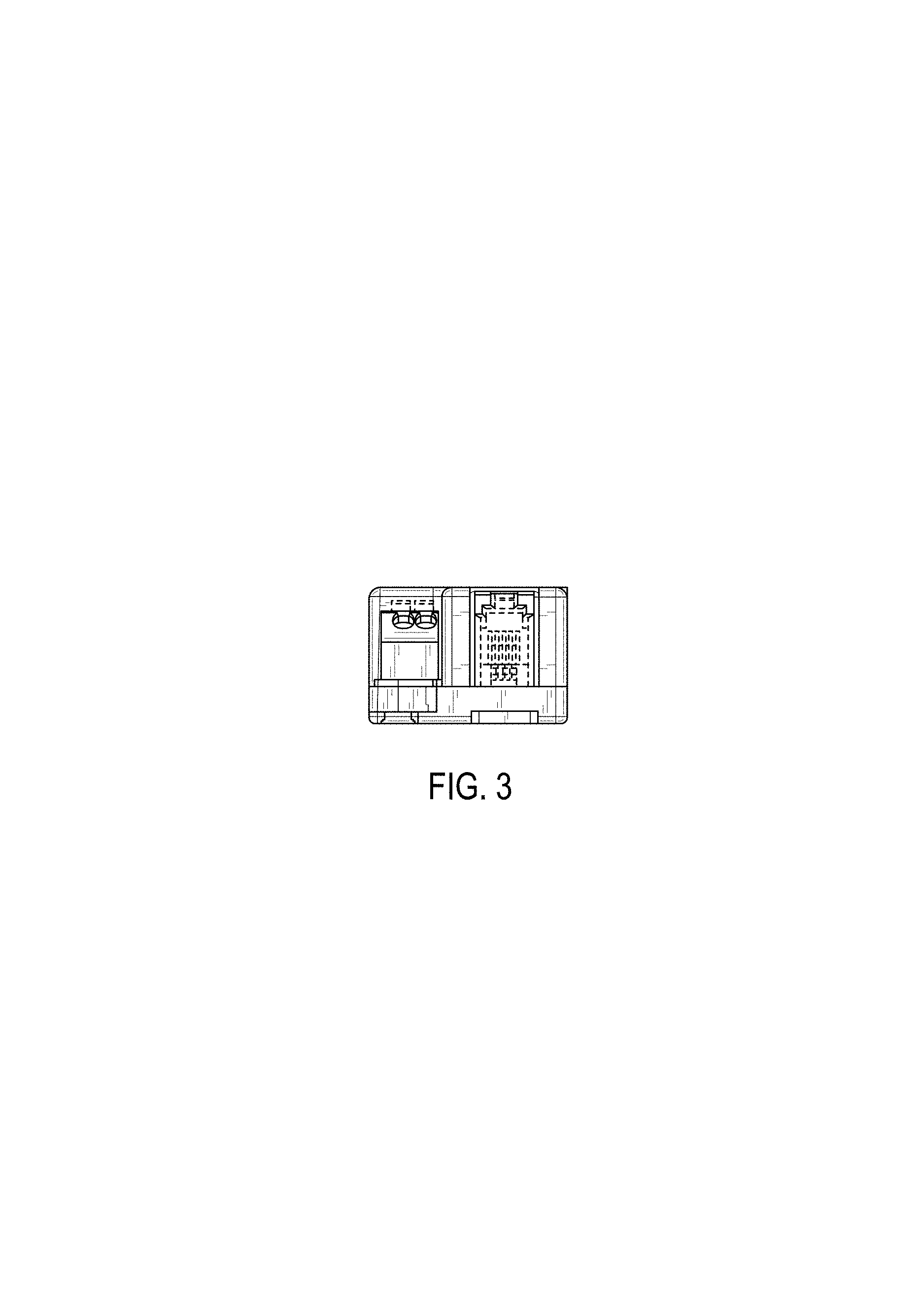
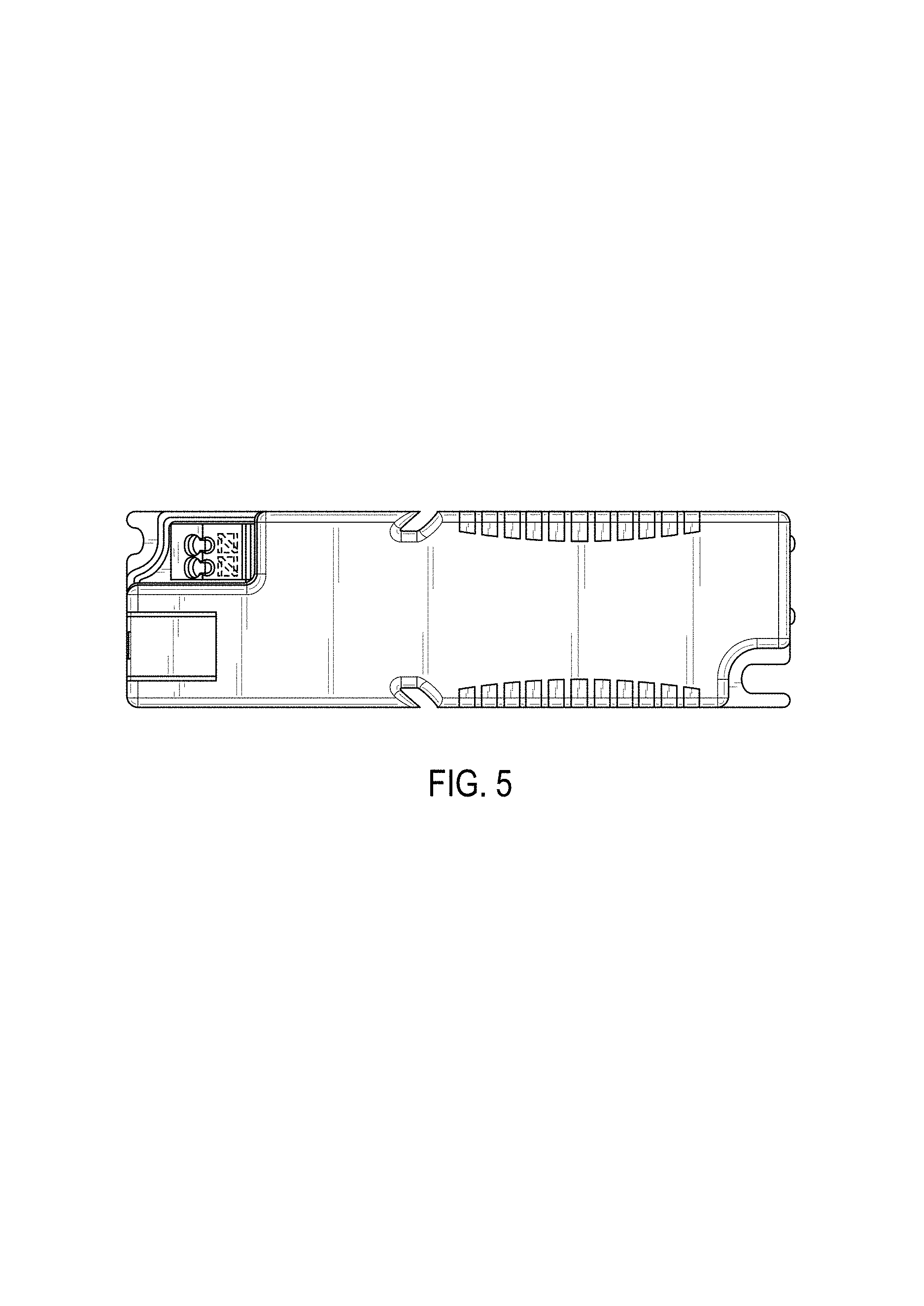
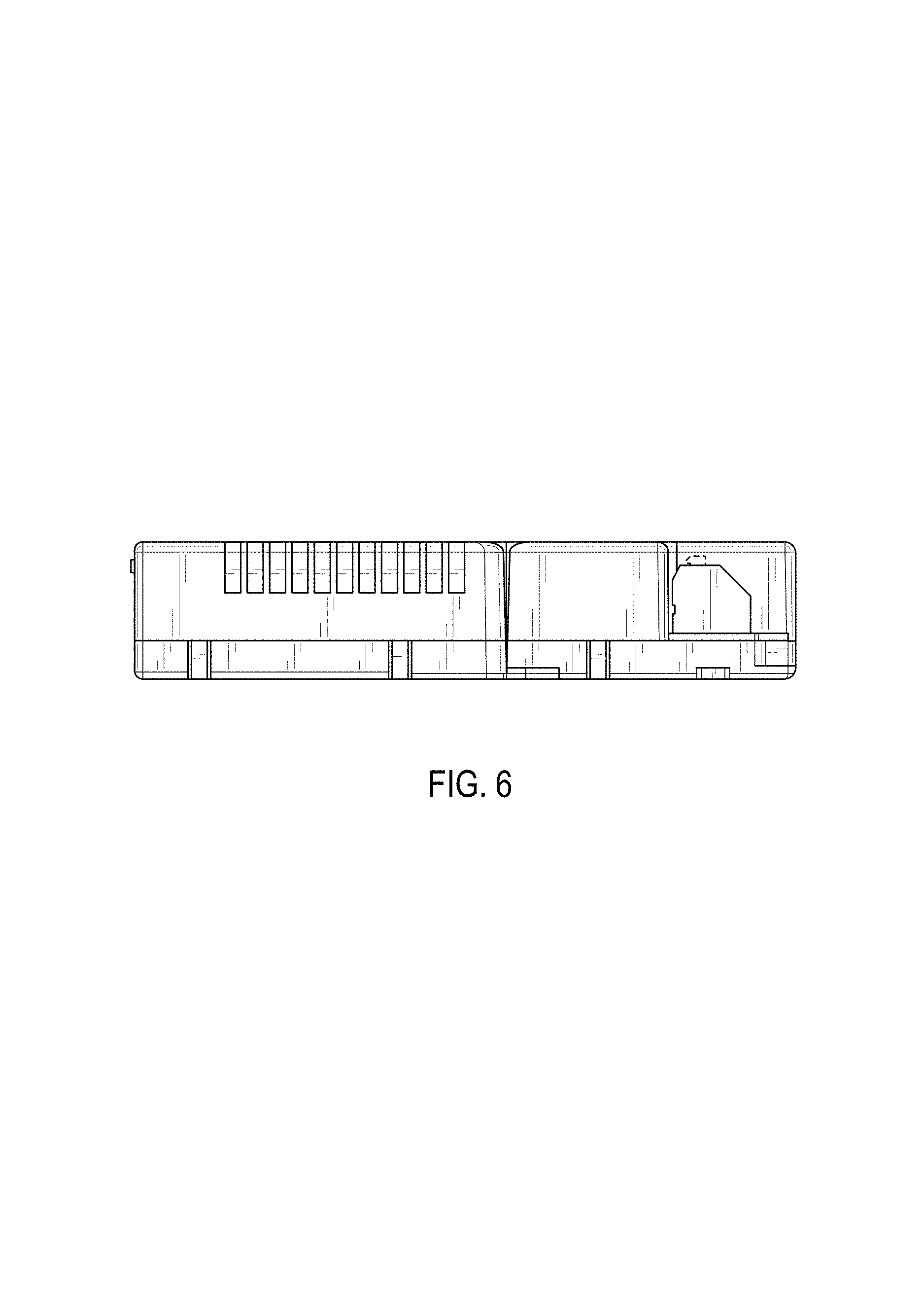
CLAIM The ornamental design for a networking device, as shown and described.
| Inventors: | Wild; Emanuel (Lustenau, AT) | ||||||||||
|---|---|---|---|---|---|---|---|---|---|---|---|
| Applicant: |
|
||||||||||
| Assignee: | Tridonic GMBH & Co., KG
(Dornbirn, AT) |
||||||||||
| Appl. No.: | D/577,146 | ||||||||||
| Filed: | September 9, 2016 |
Foreign Application Priority Data
| Mar 11, 2016 [EM] | 003 024 181 | |||
| Current U.S. Class: | D14/240 |
| Current International Class: | 1403 |
| Field of Search: | ;D14/242,240,355,357,358,125,140-140.9,155,137,139,243,239,433,314,496,188,348,351,356 |
References Cited [Referenced By]
U.S. Patent Documents
| D281493 | November 1985 | Prager |
| D304929 | December 1989 | Bench |
| D346378 | April 1994 | Smylie |
| D355196 | February 1995 | Nakamura |
| D356291 | March 1995 | Kawamura |
| D356994 | April 1995 | Tamaki |
| D361310 | August 1995 | Kawamura |
| D362839 | October 1995 | Tamaki |
| D374430 | October 1996 | Loh |
| D604241 | November 2009 | Haberle |
| D660828 | May 2012 | Petsch |
| D738869 | September 2015 | Groener |
| D764408 | August 2016 | Spiegel |
| D1545098 | Mar 2016 | JP | |||
Other References
|
LampShopOnline. <URL: https://www.lampshoponline.com/tridonic-pca-2x26-32-42-tc-eco.html.> visited Nov. 7, 2017. Tridonic high frequency dimmable ballast. cited by examiner. |
Primary Examiner: Hattan; Susan Bennett
Assistant Examiner: McVey; Lauren D
Attorney, Agent or Firm: Scully, Scott, Murphy & Presser, P.C.
Description
FIG. 1 is a rear perspective view of a networking device showing my new design;
FIG. 2 is a front perspective view thereof;
FIG. 3 is a front elevation view thereof;
FIG. 4 is a rear elevation view thereof;
FIG. 5 is a top plan view thereof;
FIG. 6 is a side elevation view thereof; and,
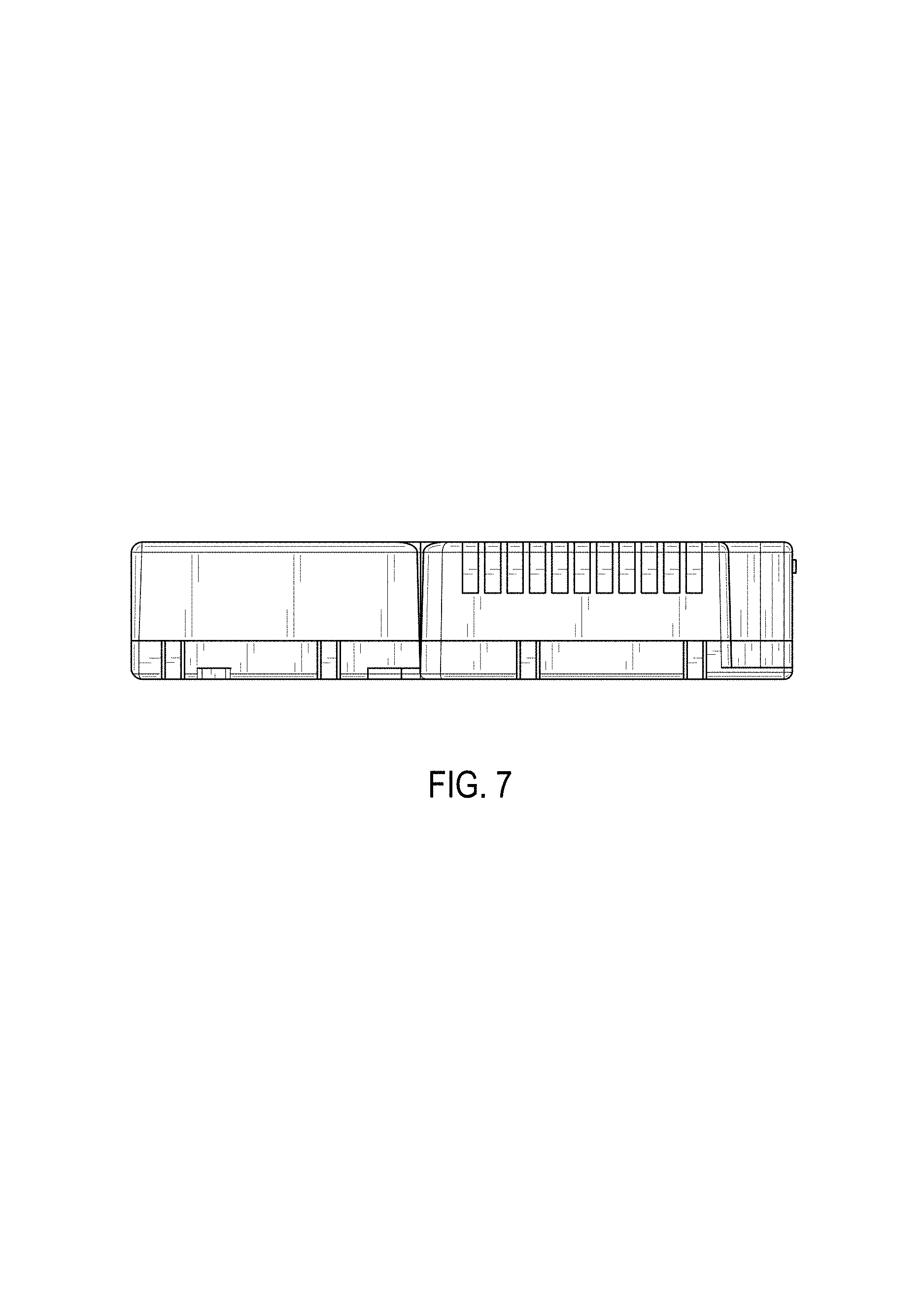
FIG. 7 is an opposite side view thereof.
The wire frame lines shown throughout the views are intended to indicate surface contour.
The broken lines are included for the purpose of illustrating portions of the article that form no part of the claimed design.
The bottom side of the article forms no part of the claimed design.
* * * * *
References
D00000
D00001
D00002
D00003
D00004
D00005
D00006
D00007
XML
uspto.report is an independent third-party trademark research tool that is not affiliated, endorsed, or sponsored by the United States Patent and Trademark Office (USPTO) or any other governmental organization. The information provided by uspto.report is based on publicly available data at the time of writing and is intended for informational purposes only.
While we strive to provide accurate and up-to-date information, we do not guarantee the accuracy, completeness, reliability, or suitability of the information displayed on this site. The use of this site is at your own risk. Any reliance you place on such information is therefore strictly at your own risk.
All official trademark data, including owner information, should be verified by visiting the official USPTO website at www.uspto.gov. This site is not intended to replace professional legal advice and should not be used as a substitute for consulting with a legal professional who is knowledgeable about trademark law.