Rod holder
Lawrence
U.S. patent number D852,538 [Application Number D/561,422] was granted by the patent office on 2019-07-02 for rod holder. The grantee listed for this patent is Reel Rack, LLC. Invention is credited to David Lawrence.


| United States Patent | D852,538 |
| Lawrence | July 2, 2019 |
Rod holder
Claims
CLAIM The ornamental design for a rod holder, as shown and described.
| Inventors: | Lawrence; David (Fort Pierce, FL) | ||||||||||
|---|---|---|---|---|---|---|---|---|---|---|---|
| Applicant: |
|
||||||||||
| Appl. No.: | D/561,422 | ||||||||||
| Filed: | April 15, 2016 |
| Current U.S. Class: | D6/552 |
| Current International Class: | 0808 |
| Field of Search: | ;D6/552,553,567,572 ;D8/380 ;D22/147,148,109 ;D25/68 ;43/21,21.2 ;211/13.1,60.1,64,70.2,70.6,70.8,65,68,69,69.8,89,94 ;248/512,520,538,316.7 |
References Cited [Referenced By]
U.S. Patent Documents
| 3298531 | January 1967 | Wilcke |
| D272787 | February 1984 | Rumbaugh |
| 4461385 | July 1984 | Clouser |
| 4583647 | April 1986 | Schinzing |
| 4871074 | October 1989 | Bryson |
| D310302 | September 1990 | Southard |
| D335233 | May 1993 | Long |
| D340608 | October 1993 | Hubbard |
| D440803 | April 2001 | McCormick |
| 6360902 | March 2002 | Searles |
| D478738 | August 2003 | Workman |
| D530960 | October 2006 | Osiecki |
| D573827 | July 2008 | Taggart |
| D597775 | August 2009 | Taggart |
| D597776 | August 2009 | Taggart |
| D685501 | July 2013 | Schildmeyer |
| D699477 | February 2014 | Allen |
| D702886 | April 2014 | Bohman |
| 2004/0140280 | July 2004 | Cleveland |
| 2005/0133473 | June 2005 | Lesperance |
| 2005/0194331 | September 2005 | Chang |
| 2007/0210021 | September 2007 | Whitehead |
| 2011/0204109 | August 2011 | Knutson |
| 2015/0216301 | August 2015 | Yates |
| 2015/0359210 | December 2015 | Rossi |
| 2018/0014642 | January 2018 | Quinto |
Assistant Examiner: Johnston; Nathan M
Attorney, Agent or Firm: Thomas; Stephen C.
Description
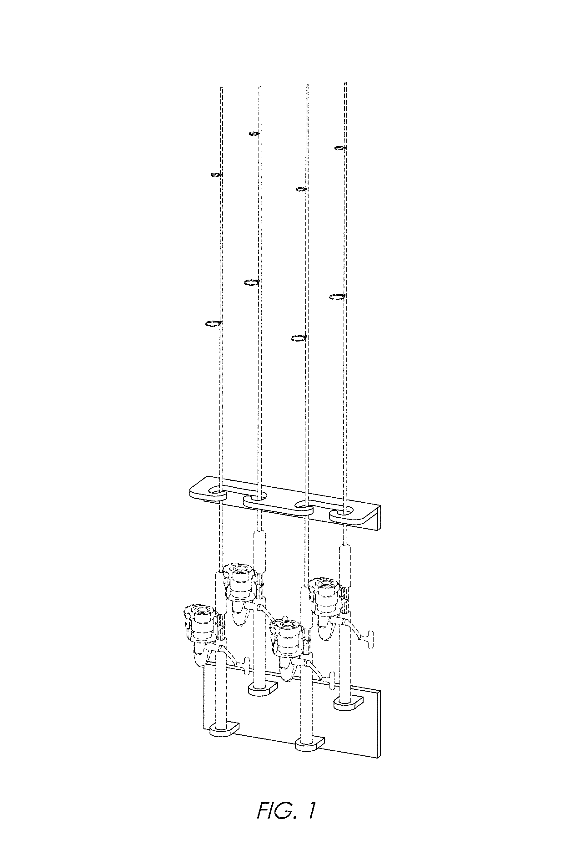
FIG. 1 is a front perspective view of the rod holder showing my new design.
FIG. 2 is a left side elevation view thereof.
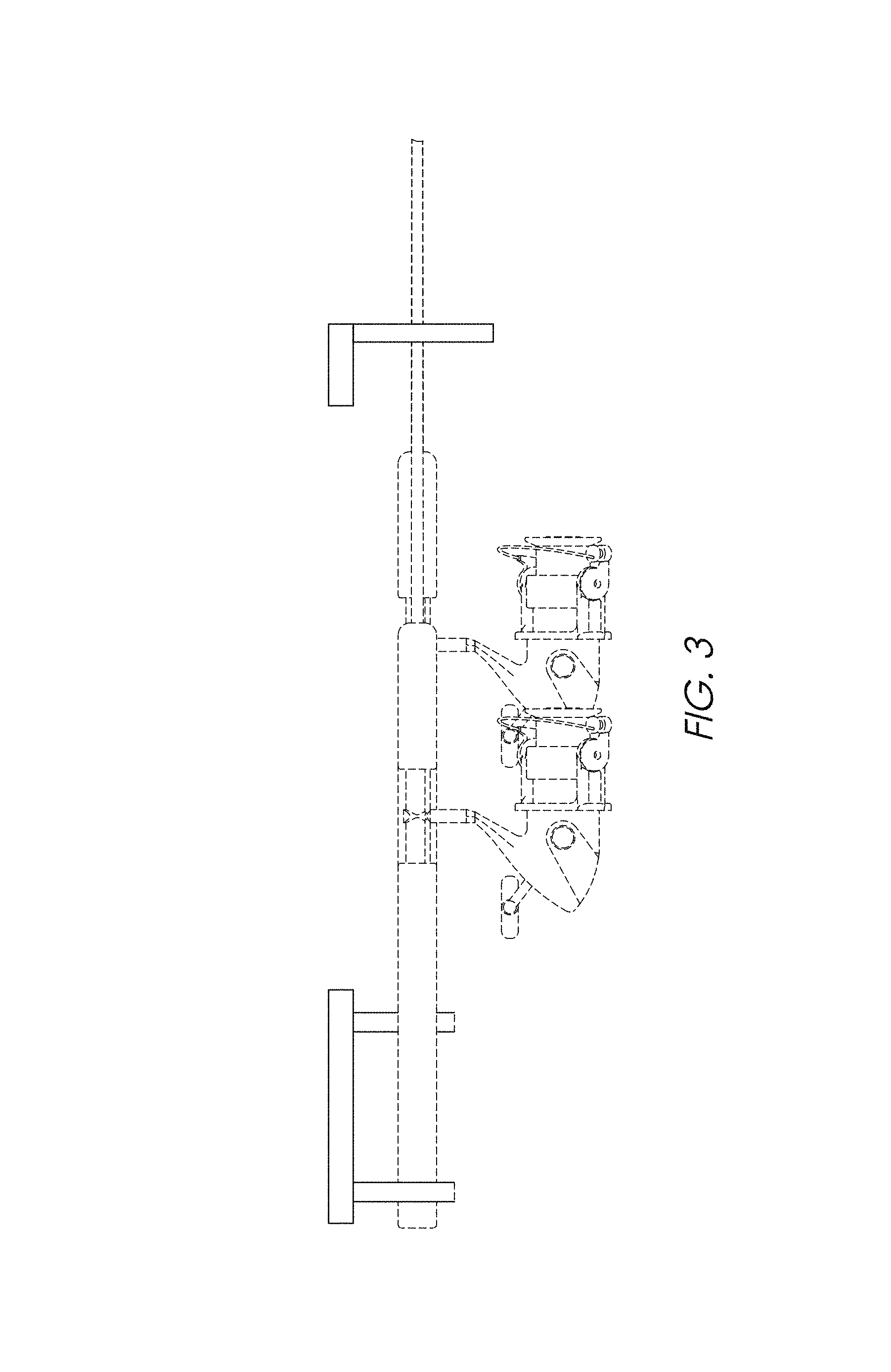
FIG. 3 is a left side elevation view of a second embodiment of FIG. 1.
FIG. 4 is a right side elevation view of the hooking member of the first and second embodiment shown separately for ease of illustration.
FIG. 5 is a top plan view thereof.
FIG. 6 is a front elevation view thereof.
FIG. 7 is a bottom plan view thereof.
FIG. 8 is a cross-sectional view thereof along line 8-8 indicated in FIG. 7.
FIG. 9 is a top plan view of the base of the rod holder of the first and second embodiment shown separately for ease of illustration.
FIG. 10 is a cross-sectional view of FIG. 9 of the first embodiment along line 10, 11 indicated in FIG. 9.
FIG. 11 is a cross-sectional view of FIG. 9 of the second embodiment along line 10, 11 indicated in FIG. 9.
FIG. 12 is a right side elevation view of the base of the rod holder of the first and second embodiment shown separately for ease of illustration.
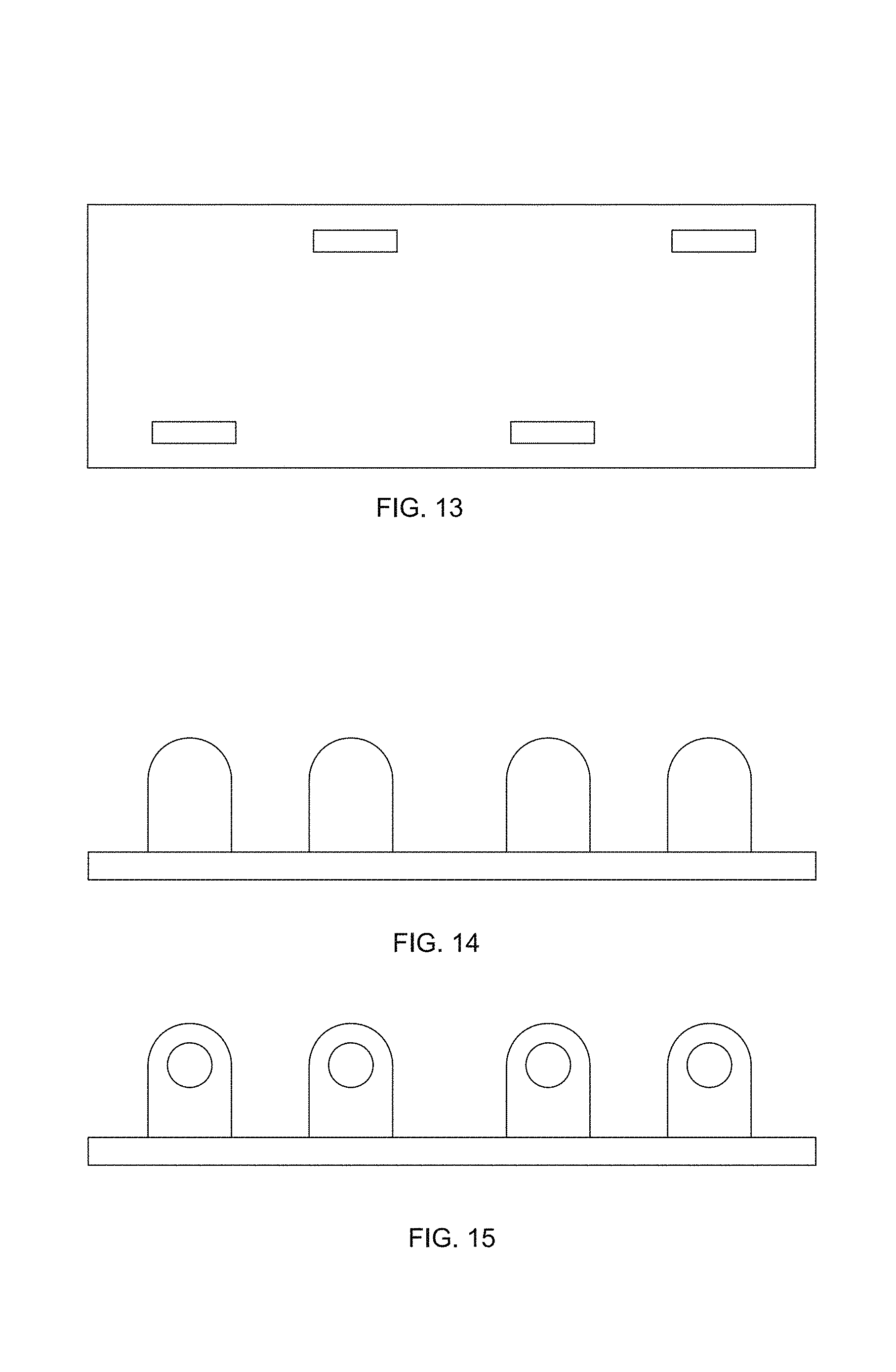
FIG. 13 is a front elevation view thereof.
FIG. 14 is a bottom plan view of first embodiment of FIG. 9; and,
FIG. 15 is a bottom plan view of second embodiment of FIG. 9.
The broken line showing of parts of the drawings is included for the purpose of illustrating use and environment and forms no part of the claimed design.
* * * * *
D00000
D00001
D00002
D00003
D00004
D00005
D00006
XML
uspto.report is an independent third-party trademark research tool that is not affiliated, endorsed, or sponsored by the United States Patent and Trademark Office (USPTO) or any other governmental organization. The information provided by uspto.report is based on publicly available data at the time of writing and is intended for informational purposes only.
While we strive to provide accurate and up-to-date information, we do not guarantee the accuracy, completeness, reliability, or suitability of the information displayed on this site. The use of this site is at your own risk. Any reliance you place on such information is therefore strictly at your own risk.
All official trademark data, including owner information, should be verified by visiting the official USPTO website at www.uspto.gov. This site is not intended to replace professional legal advice and should not be used as a substitute for consulting with a legal professional who is knowledgeable about trademark law.