Autoinjector with removable cap
Boyaval , et al.
U.S. patent number D851,754 [Application Number D/636,560] was granted by the patent office on 2019-06-18 for autoinjector with removable cap. This patent grant is currently assigned to AMGEN INC.. The grantee listed for this patent is AMGEN INC.. Invention is credited to Margaux Frances Boyaval, Sigrid Moeslinger, Masamichi Udagawa.


View All Diagrams
| United States Patent | D851,754 |
| Boyaval , et al. | June 18, 2019 |
Autoinjector with removable cap
Claims
CLAIM The ornamental design for an autoinjector with removable cap, as shown and described.
| Inventors: | Boyaval; Margaux Frances (Newbury Park, CA), Moeslinger; Sigrid (New York, NY), Udagawa; Masamichi (New York, NY) | ||||||||||
|---|---|---|---|---|---|---|---|---|---|---|---|
| Applicant: |
|
||||||||||
| Assignee: | AMGEN INC. (Thousand Oaks,
CA) |
||||||||||
| Appl. No.: | D/636,560 | ||||||||||
| Filed: | February 9, 2018 |
Related U.S. Patent Documents
| Application Number | Filing Date | Patent Number | Issue Date | ||
|---|---|---|---|---|---|
| 29561893 | Apr 20, 2016 | D814022 | |||
| Current U.S. Class: | D24/113 |
| Current International Class: | 2402 |
| Field of Search: | ;D24/112-114,133,186,127-131 ;606/181,185 ;604/264,272,115,232,187,158,164.08,192,263,163,181,184,198,227 ;600/101,139,143 ;128/200.24,207.14,207.15 ;D19/115-123,177,193 |
References Cited [Referenced By]
U.S. Patent Documents
| D321472 | November 1991 | Evans et al. |
| D443641 | June 2001 | Mader |
| D497806 | November 2004 | Nichols |
| D545895 | July 2007 | Okutani |
| D612486 | March 2010 | Van der Stappen |
| D622374 | August 2010 | Julian et al. |
| D626994 | November 2010 | Gerules |
| D627061 | November 2010 | Van der Stappen |
| D628690 | December 2010 | Galbraith |
| D629509 | December 2010 | Julian et al. |
| D696774 | December 2013 | Guarraia |
| D697205 | January 2014 | Schneider et al. |
| D708317 | July 2014 | Schneider |
| D714932 | October 2014 | Hall |
| D721802 | January 2015 | Ohashi |
| D728782 | May 2015 | Dubuc et al. |
| D757255 | May 2016 | Wohlfahrt et al. |
| D758569 | June 2016 | Wohlfahrt |
| D758570 | June 2016 | Wohlfahrt |
| D765240 | August 2016 | Hauck |
| D766425 | September 2016 | Hauck |
| D770610 | November 2016 | Saussaye |
| D773648 | December 2016 | Wohlfahrt et al. |
| D774641 | December 2016 | Miggels et al. |
| D775279 | December 2016 | Shen |
| D780909 | March 2017 | Burkett et al. |
| D794777 | August 2017 | Daniel |
| D814022 | March 2018 | Boyaval |
| D819198 | May 2018 | Boyaval |
| D819200 | May 2018 | Stonecipher |
| 2004/0068283 | April 2004 | Fukuzawa |
| 2013/0060231 | March 2013 | Adlon |
| 2014/0221936 | August 2014 | Edhouse |
| 2014/0330216 | November 2014 | Weaver |
| 2014/0343507 | November 2014 | Karlsson |
| 2014/0364812 | December 2014 | Lumme |
| 2014/0371684 | December 2014 | Holmqvist |
| 2015/0335829 | November 2015 | Giambattista |
| 2016/0263325 | September 2016 | Huthmacher et al. |
Assistant Examiner: Johnston; Nathan M
Attorney, Agent or Firm: Marshall, Gerstein & Borun LLP
Description
FIG. 1 is a perspective view showing a new design for an autoinjector with a removable cap having a cylindrical side profile, showing the removable cap disposed on the autoinjector;
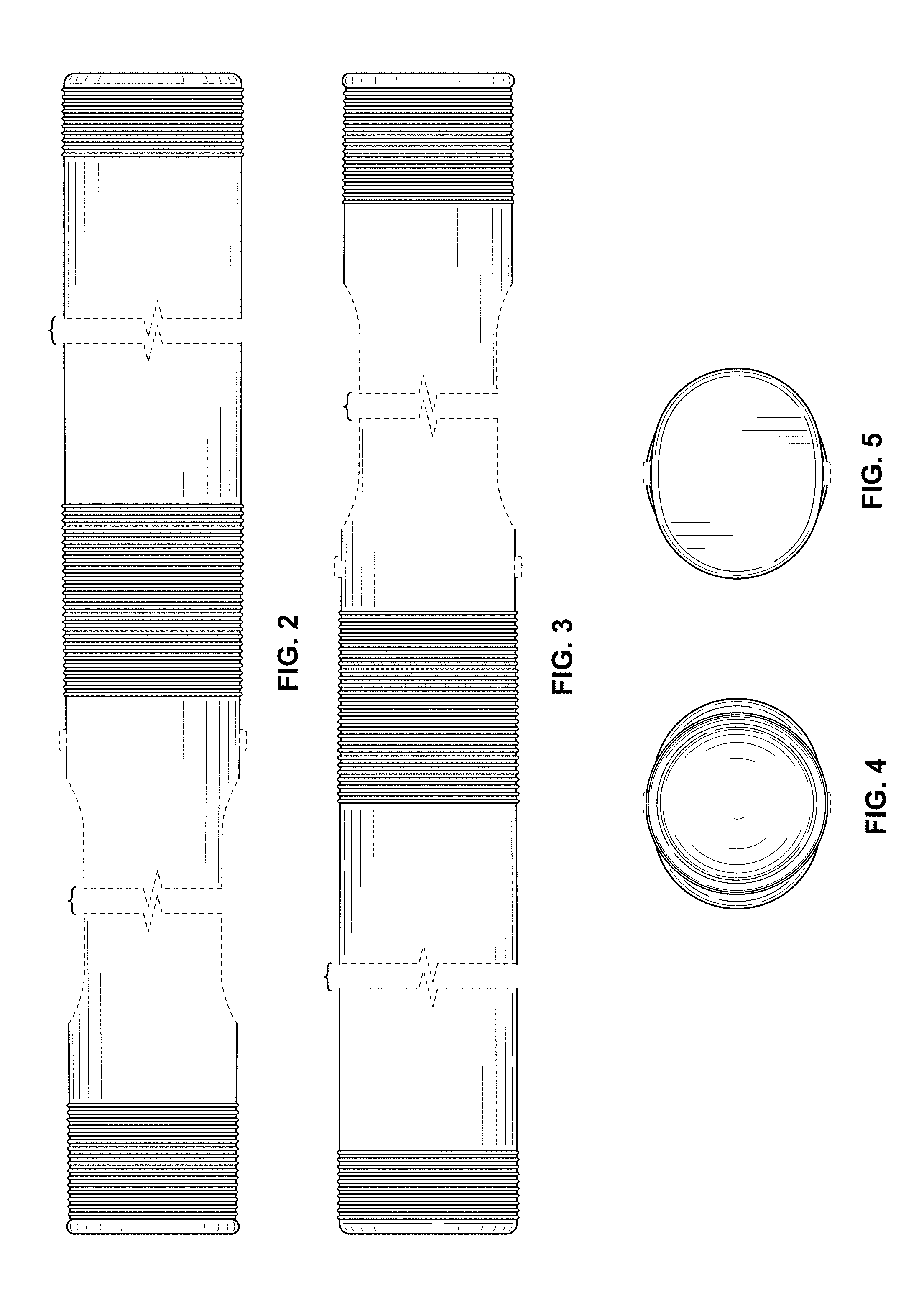
FIG. 2 is a front elevation view thereof;
FIG. 3 is a rear elevation view thereof;
FIG. 4 is a left-side elevation view thereof;
FIG. 5 is a right-side elevation view thereof;
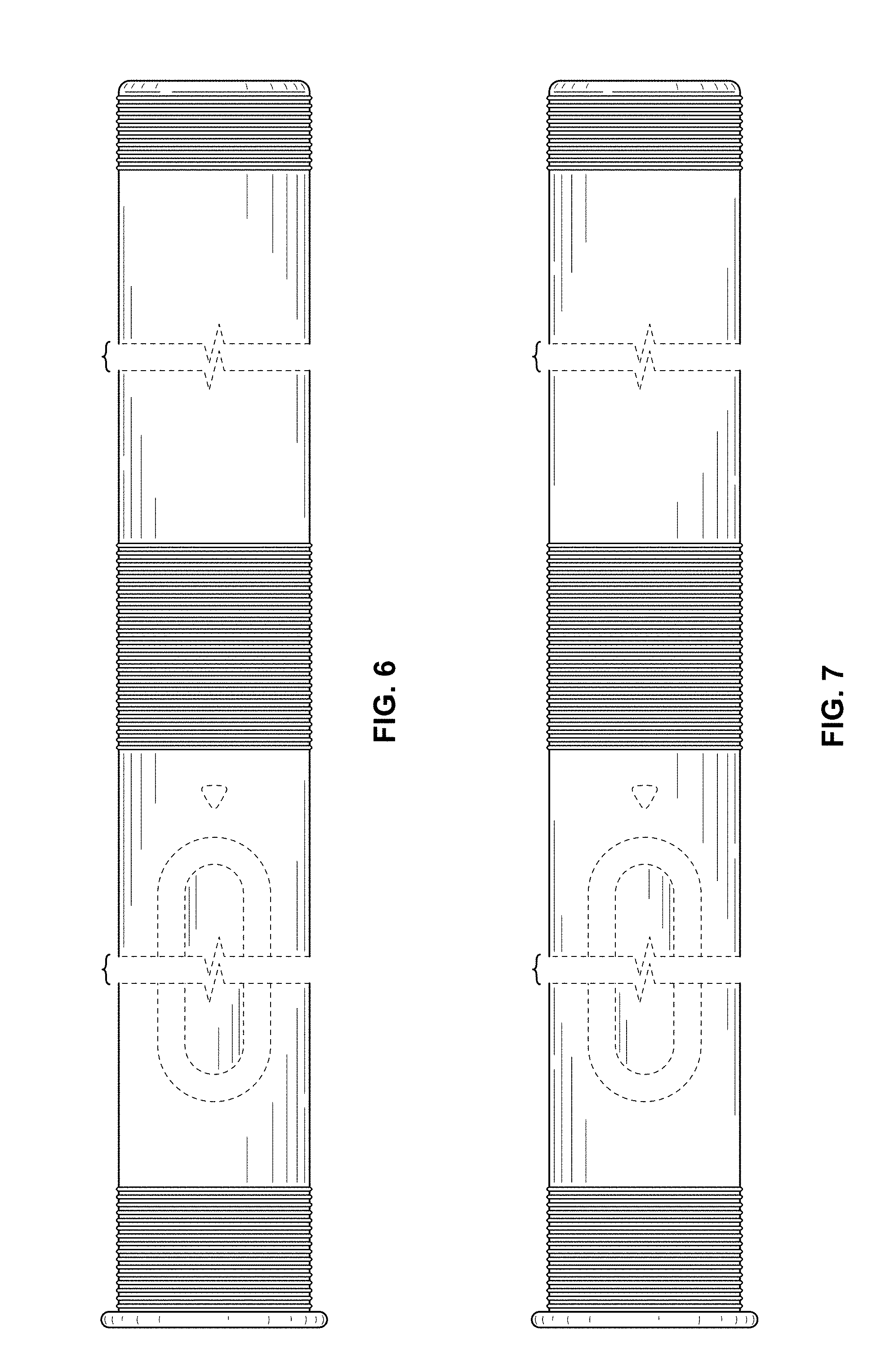
FIG. 6 is a top plan view thereof;
FIG. 7 is a bottom plan view thereof;
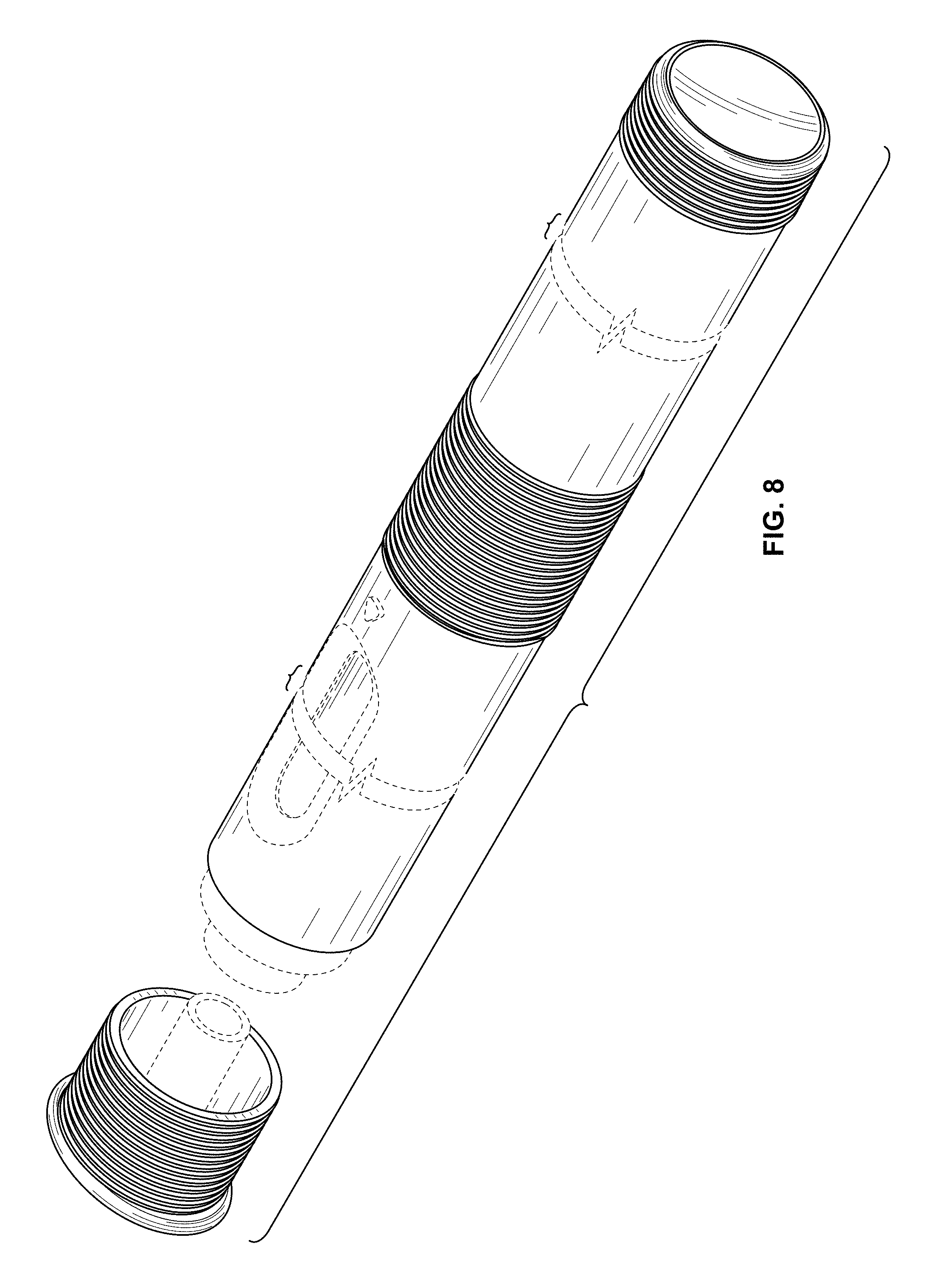
FIG. 8 is a perspective view showing the autoinjector with removable cap of FIGS. 1-7 with the removable cap removed;
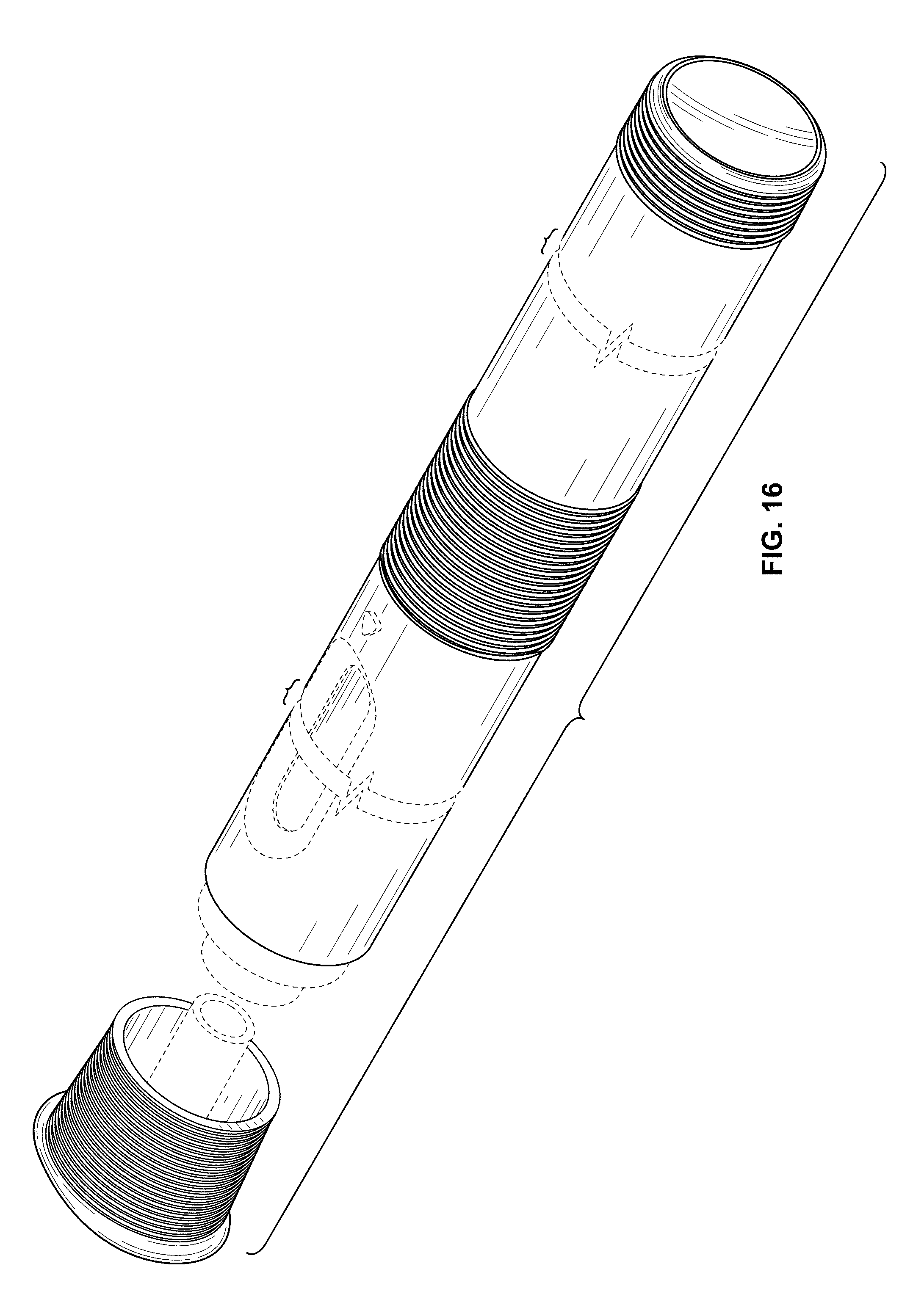
FIG. 9 is a perspective view showing an alternative new design for an autoinjector with a removable cap having a triangular shaped side profile, showing the removable cap disposed on the autoinjector;
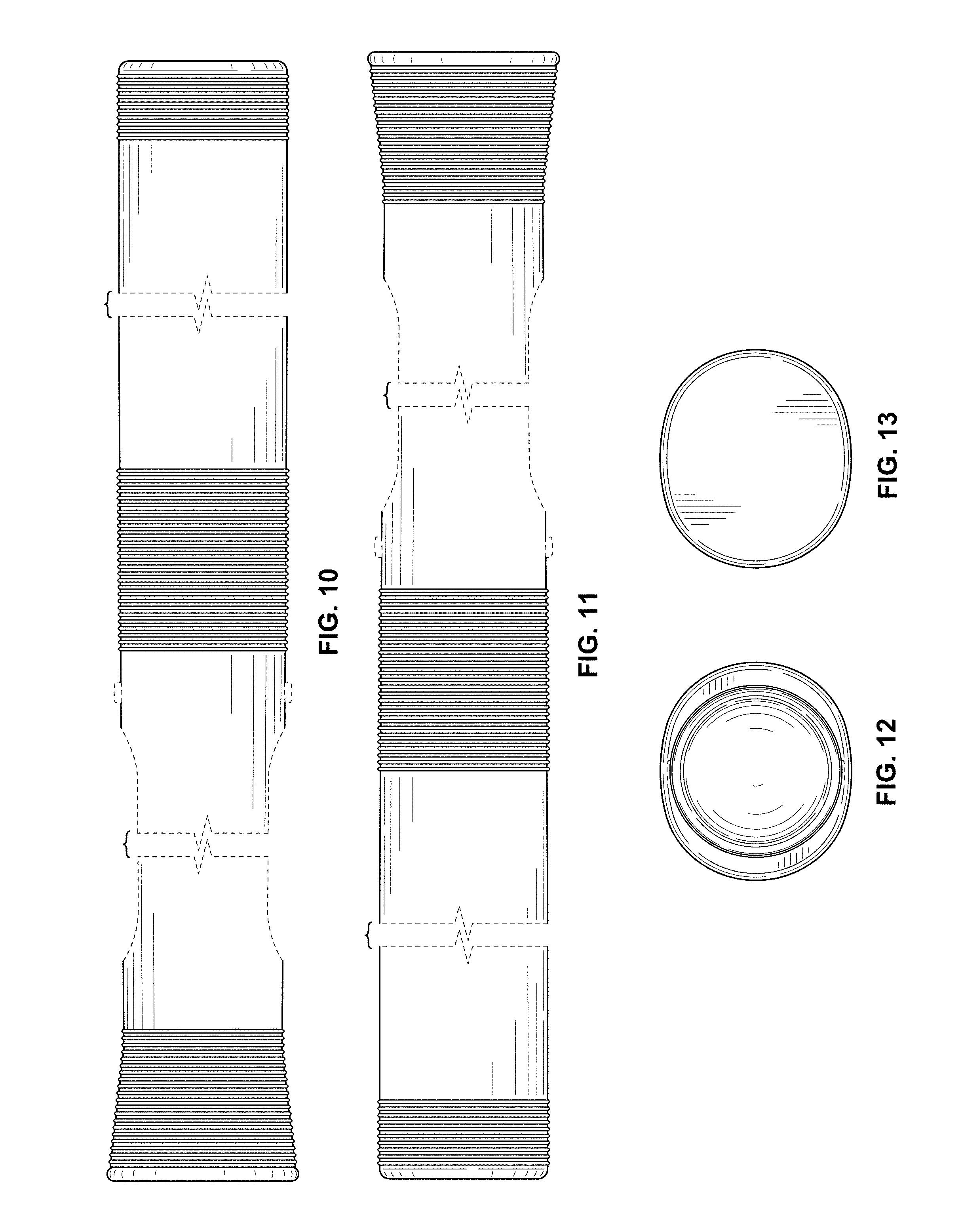
FIG. 10 is a front elevation view thereof;
FIG. 11 is a rear elevation view thereof;
FIG. 12 is a left-side elevation view thereof;
FIG. 13 is a right-side elevation view thereof;
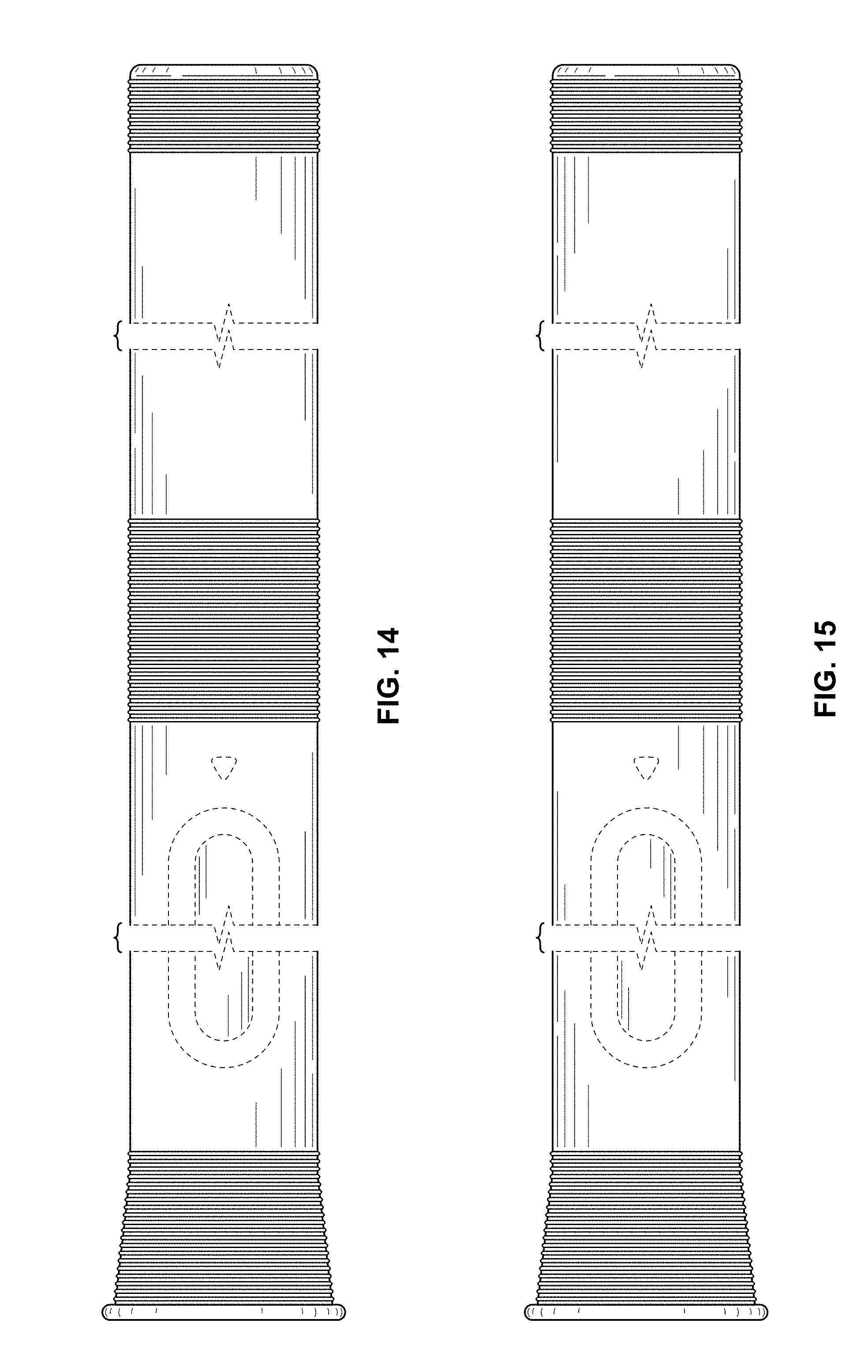
FIG. 14 is a top plan view thereof;
FIG. 15 is a bottom plan view thereof;
FIG. 16 is a perspective view showing the autoinjector with removable cap of FIGS. 9-15 with the removable cap removed;
FIG. 17 is a perspective view showing an alternative new design for an autoinjector with a removable cap having a flared side profile, showing the removable cap disposed on the autoinjector;
FIG. 18 is a front elevation view thereof;
FIG. 19 is a rear elevation view thereof;
FIG. 20 is a left-side elevation view thereof;
FIG. 21 is a right-side elevation view thereof;
FIG. 22 is a top plan view thereof;
FIG. 23 is a bottom plan view thereof; and,
FIG. 24 is a perspective view showing the autoinjector with removable cap of FIGS. 17-23 with the removable cap removed.
The dashed lines showing portions of the autoinjector drug delivery device are included for the purpose of illustrating environment and form no part of the claimed design.
The autoinjector with removable cap is shown with a symbolic break in its length. The appearance of any portion of the article between the break lines forms no part of the claimed design.
* * * * *
D00000
D00001
D00002
D00003
D00004
D00005
D00006
D00007
D00008
D00009
D00010
D00011
D00012

XML
uspto.report is an independent third-party trademark research tool that is not affiliated, endorsed, or sponsored by the United States Patent and Trademark Office (USPTO) or any other governmental organization. The information provided by uspto.report is based on publicly available data at the time of writing and is intended for informational purposes only.
While we strive to provide accurate and up-to-date information, we do not guarantee the accuracy, completeness, reliability, or suitability of the information displayed on this site. The use of this site is at your own risk. Any reliance you place on such information is therefore strictly at your own risk.
All official trademark data, including owner information, should be verified by visiting the official USPTO website at www.uspto.gov. This site is not intended to replace professional legal advice and should not be used as a substitute for consulting with a legal professional who is knowledgeable about trademark law.