False bottom tube with cap and plug
Jackson , et al.
U.S. patent number D850,647 [Application Number D/574,966] was granted by the patent office on 2019-06-04 for false bottom tube with cap and plug. This patent grant is currently assigned to DNA GENOTEK INC.. The grantee listed for this patent is DNA Genotek Inc.. Invention is credited to Lawrence Dickson, Rafal Michal Iwasiow, Adele Jackson, Jonathan David Liberty, Kenneth Oscar Olson.


View All Diagrams
| United States Patent | D850,647 |
| Jackson , et al. | June 4, 2019 |
False bottom tube with cap and plug
Claims
CLAIM The ornamental design for a false bottom tube with cap and plug, as shown and described.
| Inventors: | Jackson; Adele (Stittsville, CA), Iwasiow; Rafal Michal (Ottawa, CA), Liberty; Jonathan David (Toronto, CA), Dickson; Lawrence (Almonte, CA), Olson; Kenneth Oscar (Ottawa, CA) | ||||||||||
|---|---|---|---|---|---|---|---|---|---|---|---|
| Applicant: |
|
||||||||||
| Assignee: | DNA GENOTEK INC.
(CA) |
||||||||||
| Appl. No.: | D/574,966 | ||||||||||
| Filed: | August 19, 2016 |
| Current U.S. Class: | D24/224 |
| Current International Class: | 2402 |
| Field of Search: | ;D24/107,121,133,216,222-230,233 ;D9/523,547,549,550,724,732 |
References Cited [Referenced By]
U.S. Patent Documents
| D244555 | May 1977 | Wiedmann |
| D252612 | August 1979 | Mull |
| D255092 | May 1980 | Wong |
| D344804 | March 1994 | Muniz |
| D432245 | October 2000 | Stevens |
| D457247 | May 2002 | Iheme |
| 6893612 | May 2005 | Kacian |
| D529817 | October 2006 | Francavilla |
| D627081 | November 2010 | Giraud |
| D640797 | June 2011 | Wilkinson |
| D743571 | November 2015 | Jackson |
| 2012/0048827 | March 2012 | Levin |
| 2017/0072393 | March 2017 | Jackson |
Other References
|
DNA Genotek's Blog. [online] Published on Oct. 17, 2011. Retrieved Jul. 5, 2018 from URL: http://blog.dnagenotek.com/topic/dna-identification. cited by examiner . PD-BR-017. [online] Published on Dec. 9, 2017. Retrieved Jun. 21, 2018 from URL: https://www.dnagenotek.com/ROW/pdf/PD-BR-017.pdf. cited by examiner . May 29, 2017 CA Office Action, Canadian Appl. No. 172754, 3 pages (Canadian Design No. 172754, foreign counterpart to U.S. Appl. No. 29/574,966). cited by applicant . Mar. 17, 2017 IN Office Action, Indian Appl. No. 290773, 2 pages (Indian Design Reg. No. 290773, foreign counterpart to U.S. Appl. No. 29/574,966). cited by applicant . Mar. 17, 2017 IN Office Action, Mar. 17, 2017, Indian Appl. No. 290774, 2 pages (Indian Design Reg. No. 290774, foreign counterpart to U.S. Appl. No. 29/574,966). cited by applicant . Jun. 6, 2017 JP Office Action with English translation (JP Design No. 1584718, foreign counterpart to U.S. Appl. No. 29/574,966). cited by applicant . Jun. 6, 2017 Office Action, JP Design No. 1584911 (issued); (substantive portions of Jun. 6. 2017 office actions for each of JP Design Nos. 15814718, 1584911 and 1584912 are the same; for English translation of substantive portion of JP Design No. 1584911, see English translation of Jun. 6, 2017 office action for JP Design No. 15814718). cited by applicant . Jun. 6, 2017 Office Action, JP Design No. 1584912 (issued); (substantive portions of Jun. 6, 2017 office actions for each of JP Design Nos. 15814718, 1584911 and 1584912 are the same; for English translation of substantive portion of JP Design No. 1584911 see English translation of Jun. 6, 2017 office action for JP Design No. 15814718). cited by applicant. |
Primary Examiner: Koenig; Vy N
Attorney, Agent or Firm: Cook Alex Ltd.
Description
FIG. 1 is a front view of the false bottom tube with cap and plug illustrating a first embodiment of the present design, with the back view being identical;
FIG. 2 is a top view of the false bottom tube with cap and plug illustrating the present design as shown in FIG. 1;
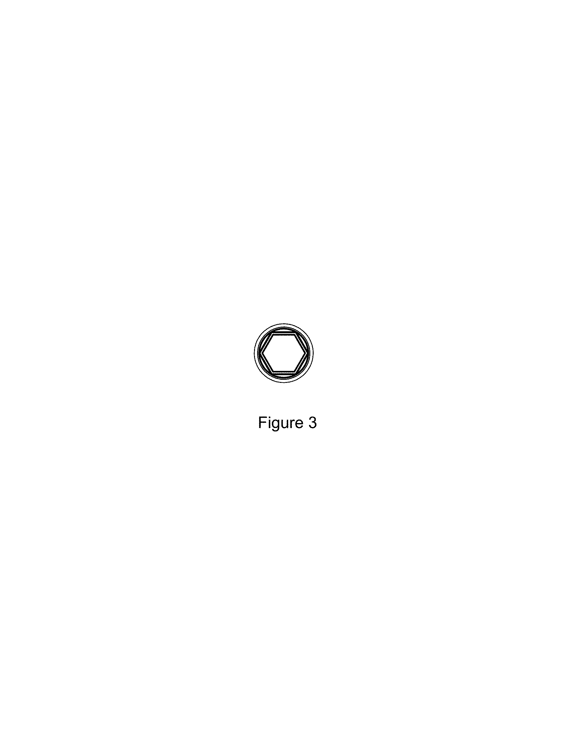
FIG. 3 is a bottom view of the false bottom tube with cap and plug illustrating the present design as shown in FIG. 1;
FIG. 4 is a left side view of the false bottom tube with cap and plug illustrating the present design as shown in FIG. 1;
FIG. 5 is a cross-sectional view through line A-A of the false bottom tube with cap and plug as shown in FIG. 4;
FIG. 6 is a right side view of the false bottom tube with cap and plug illustrating the present design as shown in FIG. 1;
FIG. 7 is a cross-sectional view through line B-B of the false bottom tube with cap and plug as shown in FIG. 6;
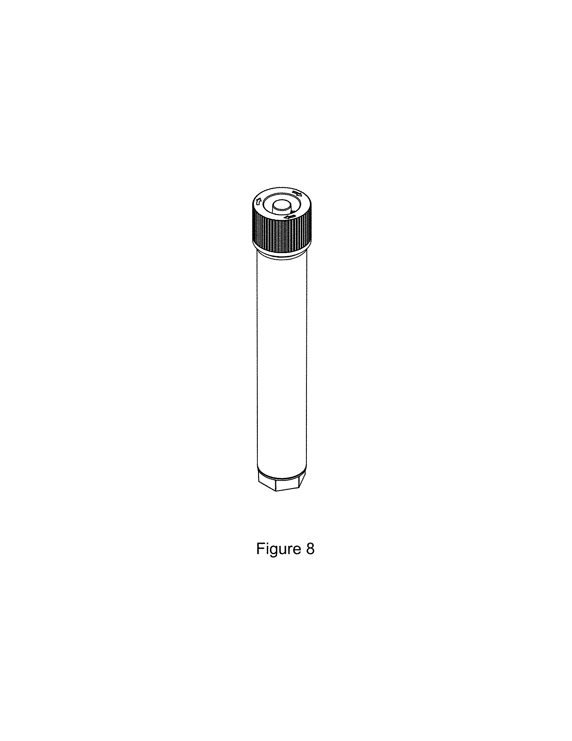
FIG. 8 is a perspective view of the false bottom tube with cap and plug illustrating the present design as shown in FIG. 1;
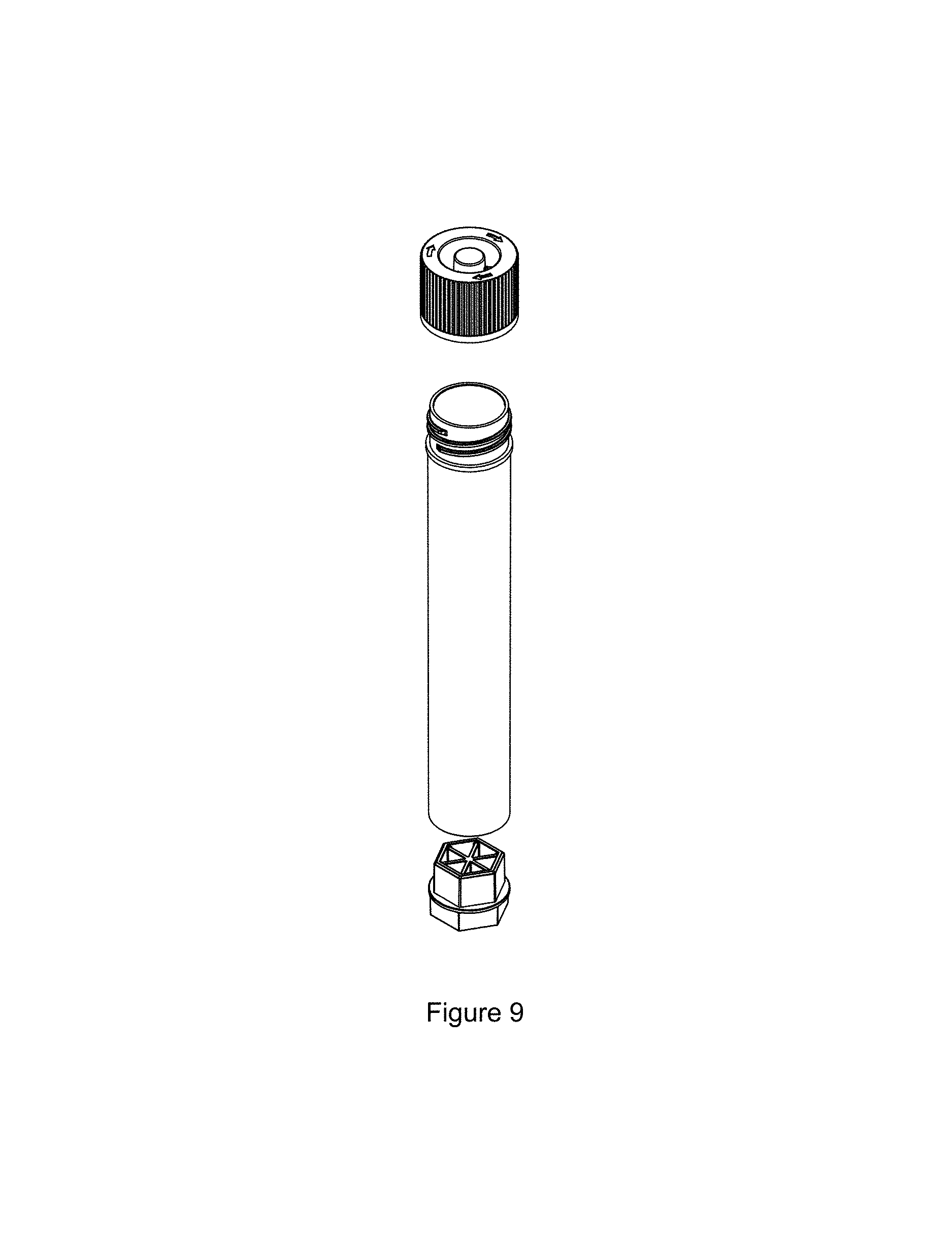
FIG. 9 is a perspective exploded view of the false bottom tube with cap and plug illustrating the present design as shown in FIG. 1;
FIG. 10 is a front view of the false bottom tube with cap and plug illustrating a second embodiment of the present design, with the back view being identical;
FIG. 11 is a top view of the false bottom tube with cap and plug as shown in FIG. 10;
FIG. 12 is a bottom view of the false bottom tube with cap and plug as shown in FIG. 10;
FIG. 13 is a left view of the false bottom tube with cap and plug as shown in FIG. 10;
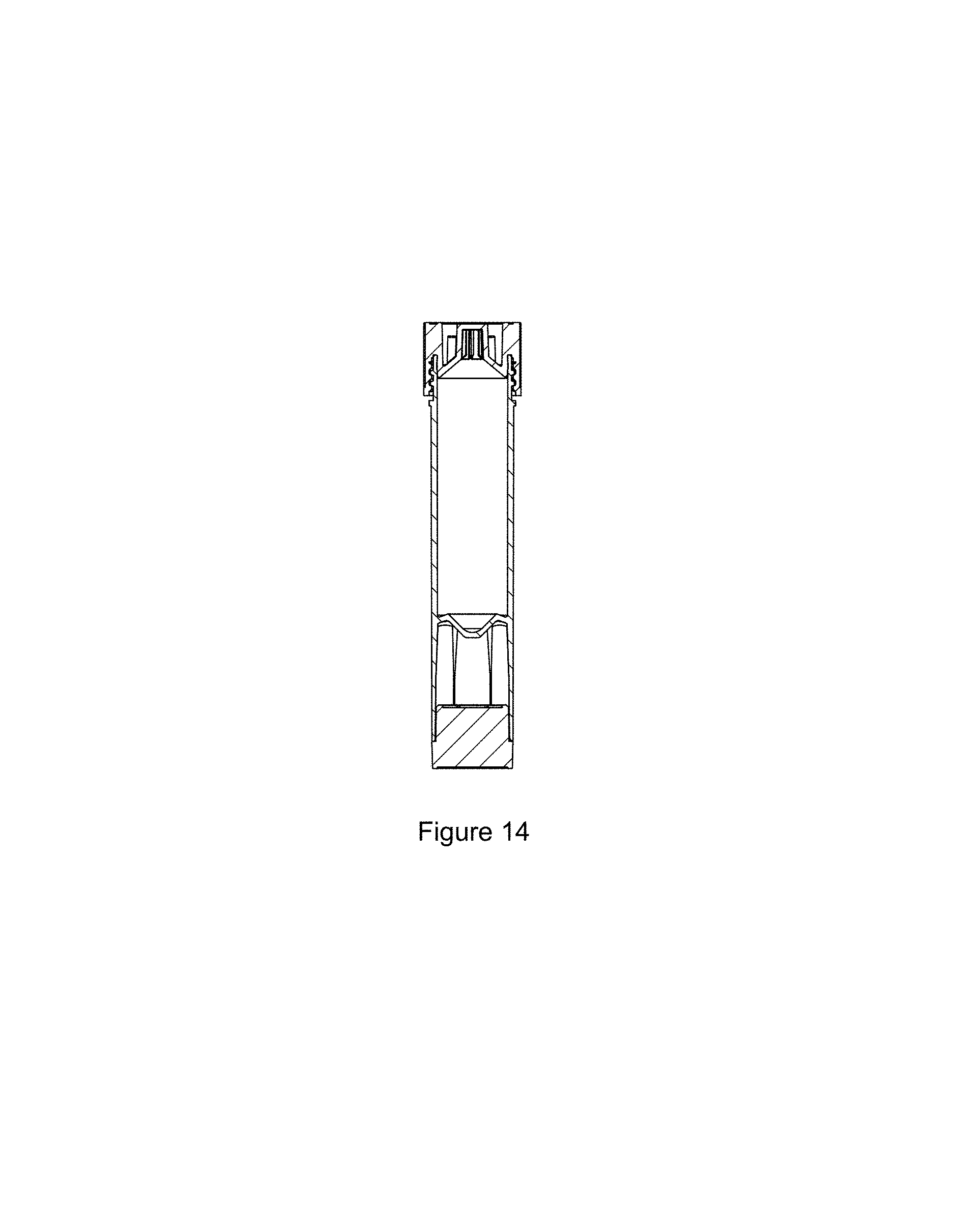
FIG. 14 is a cross-sectional view through line D-D of the false bottom tube with cap and plug as shown in FIG. 13;
FIG. 15 is a right side view of the false bottom tube with cap and plug illustrating the present design as shown in FIG. 10;
FIG. 16 is a cross-sectional view through line E-E of the false bottom tube with cap and plug as shown in FIG. 15;
FIG. 17 is a perspective view of the false bottom tube with cap and plug illustrating the present design as shown in FIG. 10; and,
FIG. 18 is a perspective exploded view of the false bottom tube with cap and plug illustrating the present design as shown in FIG. 10.
* * * * *
References
D00000
D00001
D00002
D00003
D00004
D00005
D00006
D00007
D00008
D00009
D00010
D00011
D00012

D00013

D00014
D00015

D00016

D00017

D00018

XML
uspto.report is an independent third-party trademark research tool that is not affiliated, endorsed, or sponsored by the United States Patent and Trademark Office (USPTO) or any other governmental organization. The information provided by uspto.report is based on publicly available data at the time of writing and is intended for informational purposes only.
While we strive to provide accurate and up-to-date information, we do not guarantee the accuracy, completeness, reliability, or suitability of the information displayed on this site. The use of this site is at your own risk. Any reliance you place on such information is therefore strictly at your own risk.
All official trademark data, including owner information, should be verified by visiting the official USPTO website at www.uspto.gov. This site is not intended to replace professional legal advice and should not be used as a substitute for consulting with a legal professional who is knowledgeable about trademark law.