Cassette with magnet
Malouf , et al.
U.S. patent number D849,740 [Application Number D/626,618] was granted by the patent office on 2019-05-28 for cassette with magnet. This patent grant is currently assigned to Cochlear Limited. The grantee listed for this patent is Cochlear Limited. Invention is credited to Matthew Cutts, Roger Leigh, Angela Lemmerz, Christopher Malouf.


View All Diagrams
| United States Patent | D849,740 |
| Malouf , et al. | May 28, 2019 |
Cassette with magnet
Claims
CLAIM The ornamental design for cassette with magnet, as shown and described.
| Inventors: | Malouf; Christopher (Ryde, AU), Lemmerz; Angela (Macquarie Park, AU), Cutts; Matthew (Kellyville, AU), Leigh; Roger (North Epping, AU) | ||||||||||
|---|---|---|---|---|---|---|---|---|---|---|---|
| Applicant: |
|
||||||||||
| Assignee: | Cochlear Limited (NSW,
AU) |
||||||||||
| Appl. No.: | D/626,618 | ||||||||||
| Filed: | November 17, 2017 |
| Current U.S. Class: | D14/299 |
| Current International Class: | 1499 |
| Field of Search: | ;D14/224-229 ;D16/244 ;D17/99 ;D6/681 ;248/125.1,166,185.1 ;381/355,359,361-363,365,366,369,375 ;379/428.01,428.04,431,433.03 ;D10/104.1 ;607/57 |
References Cited [Referenced By]
U.S. Patent Documents
| D105226 | July 1937 | Moore |
| 5105811 | April 1992 | Kuzma |
| 6648914 | November 2003 | Berrang |
| 7534127 | May 2009 | Parker |
| D629202 | December 2010 | Wai |
| D676955 | February 2013 | Orome |
| 8454668 | June 2013 | Asnes |
| 8489195 | July 2013 | Dalton |
| 8532783 | September 2013 | Zimmerling |
| 8771166 | July 2014 | Conn |
| 8950715 | February 2015 | Chiu |
| D760392 | June 2016 | Jurkiewicz |
| 10097934 | October 2018 | Meskens |
Attorney, Agent or Firm: Finnegan, Henderson, Farabow, Garrett & Dunner LLP
Description
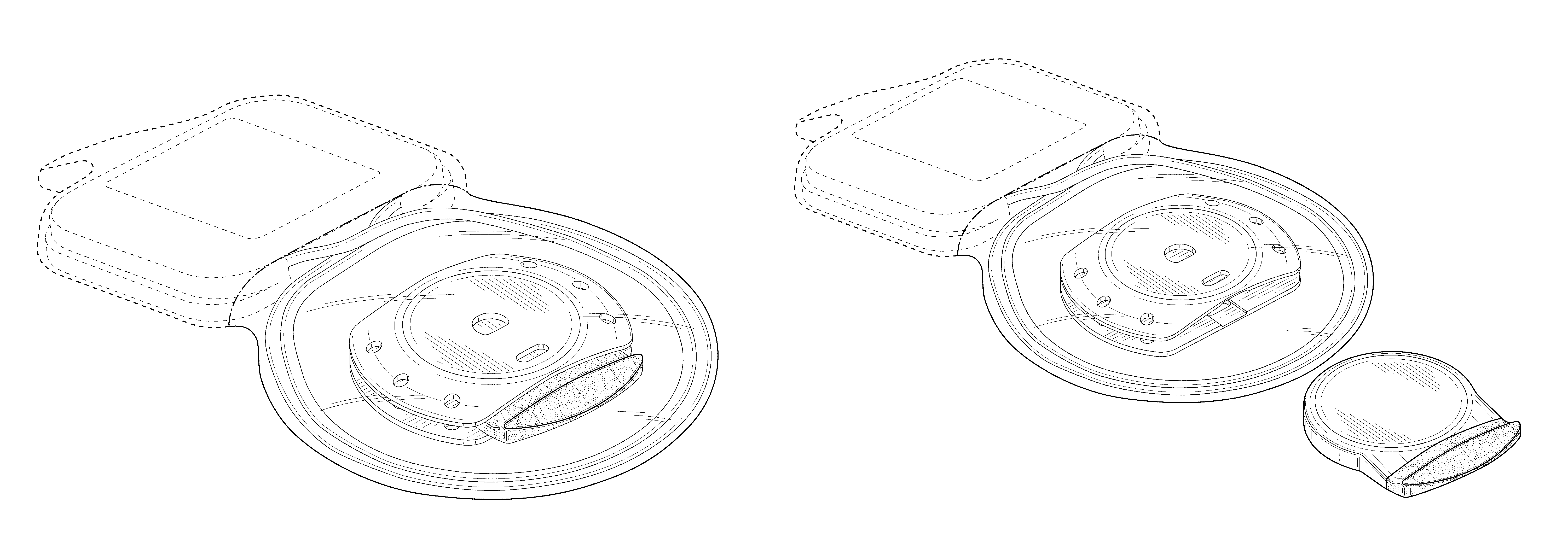
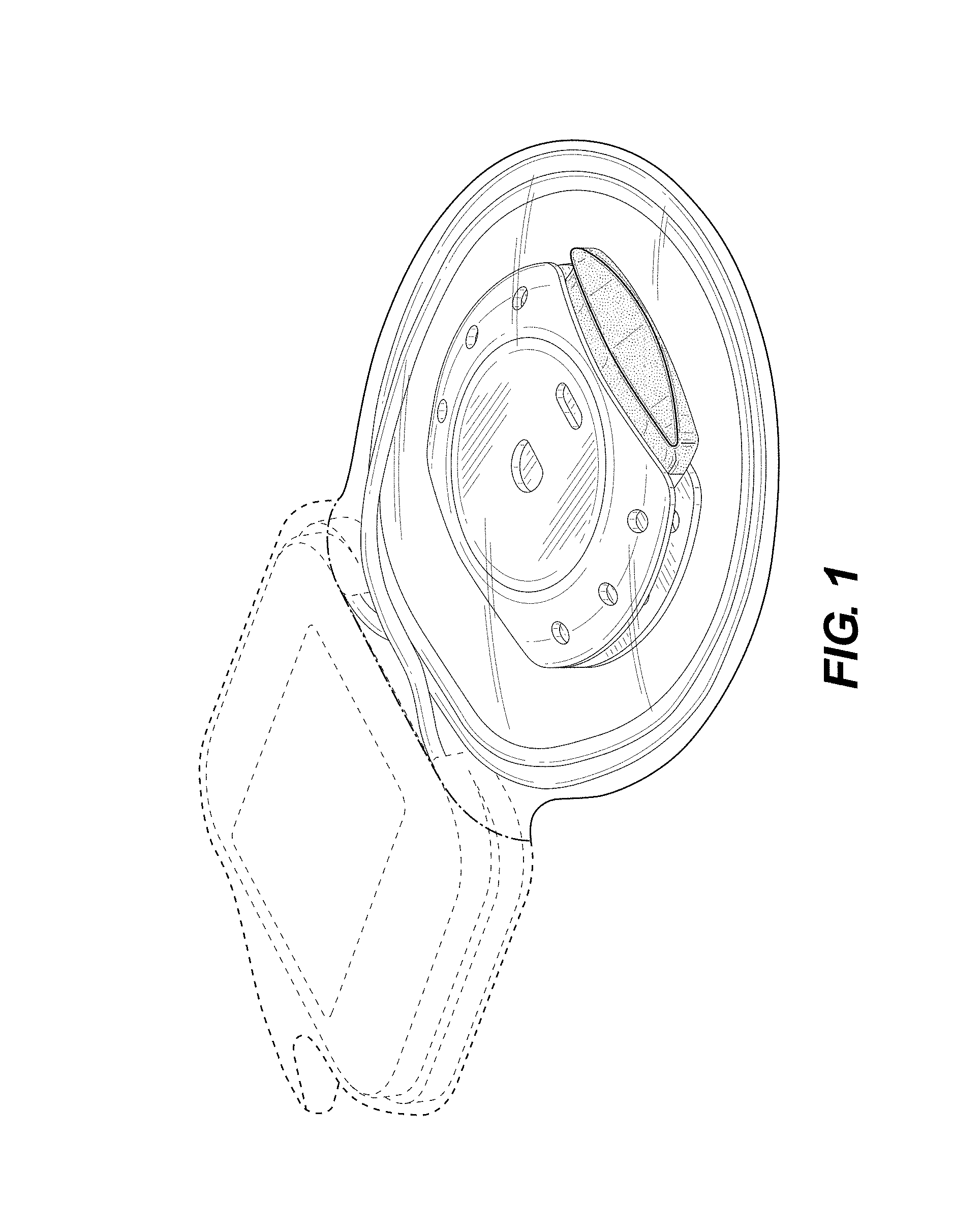
FIG. 1 is a top, front, right perspective view of a cassette with magnet showing our new design;
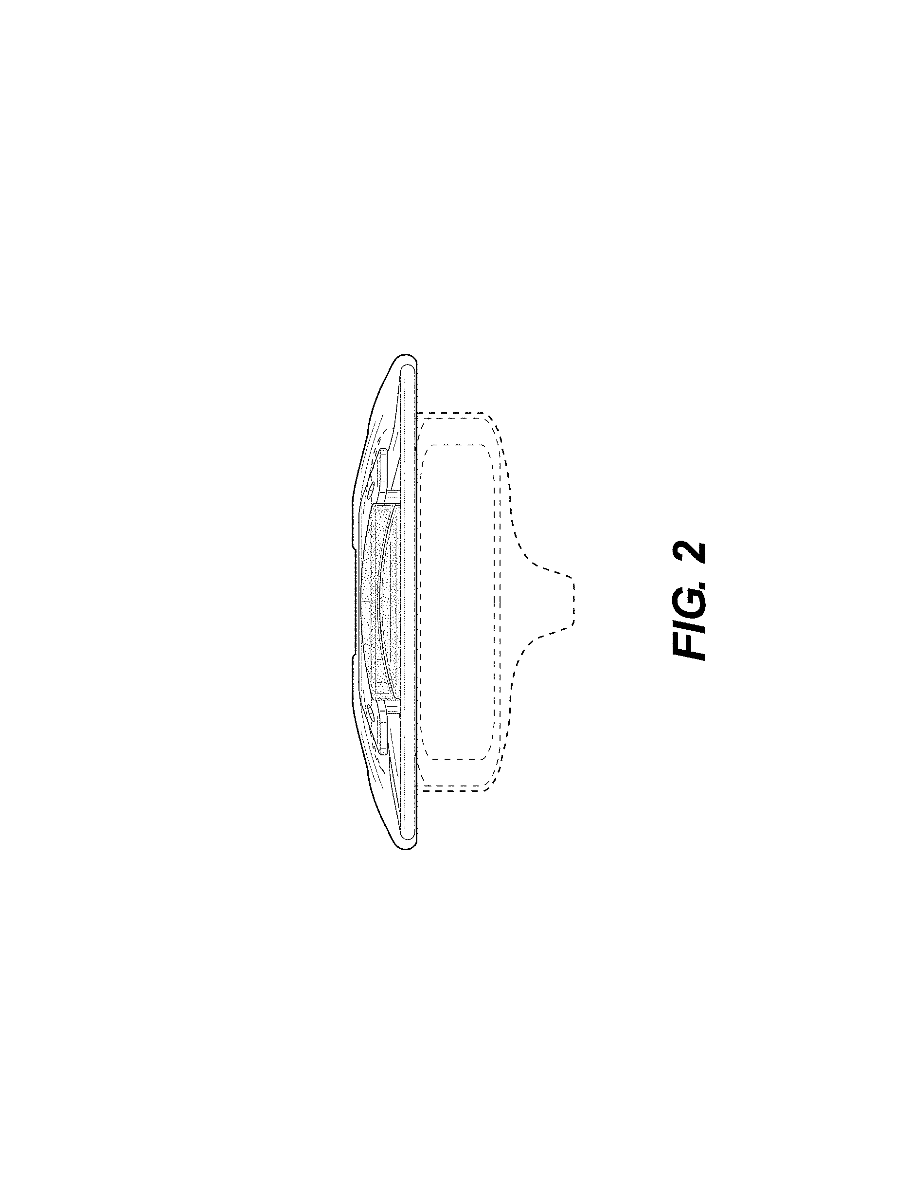
FIG. 2 is a top plan view thereof;
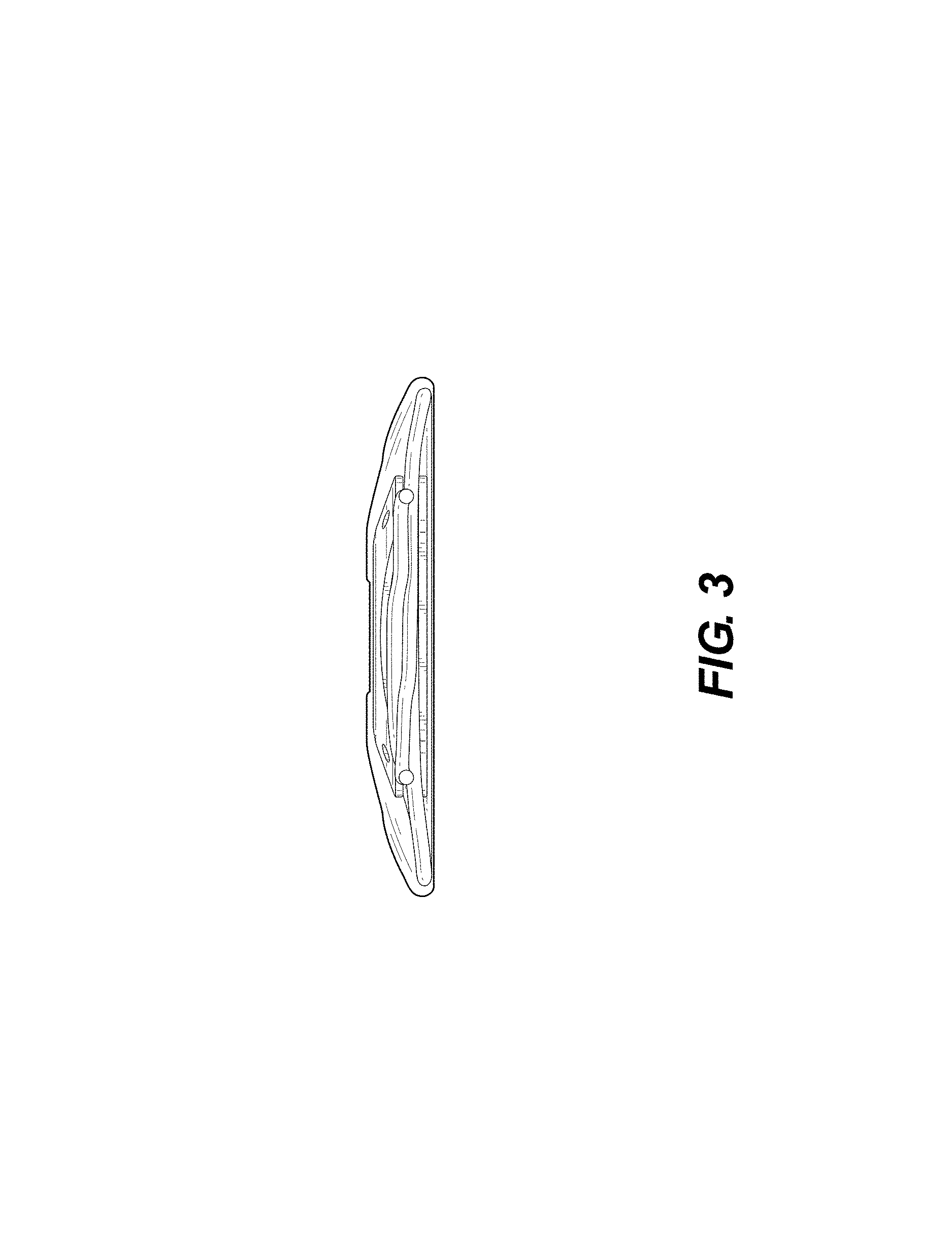
FIG. 3 is a bottom plan view thereof with a portion of the unclaimed subject matter removed to show the interior coil;
FIG. 4 is a left side view thereof;
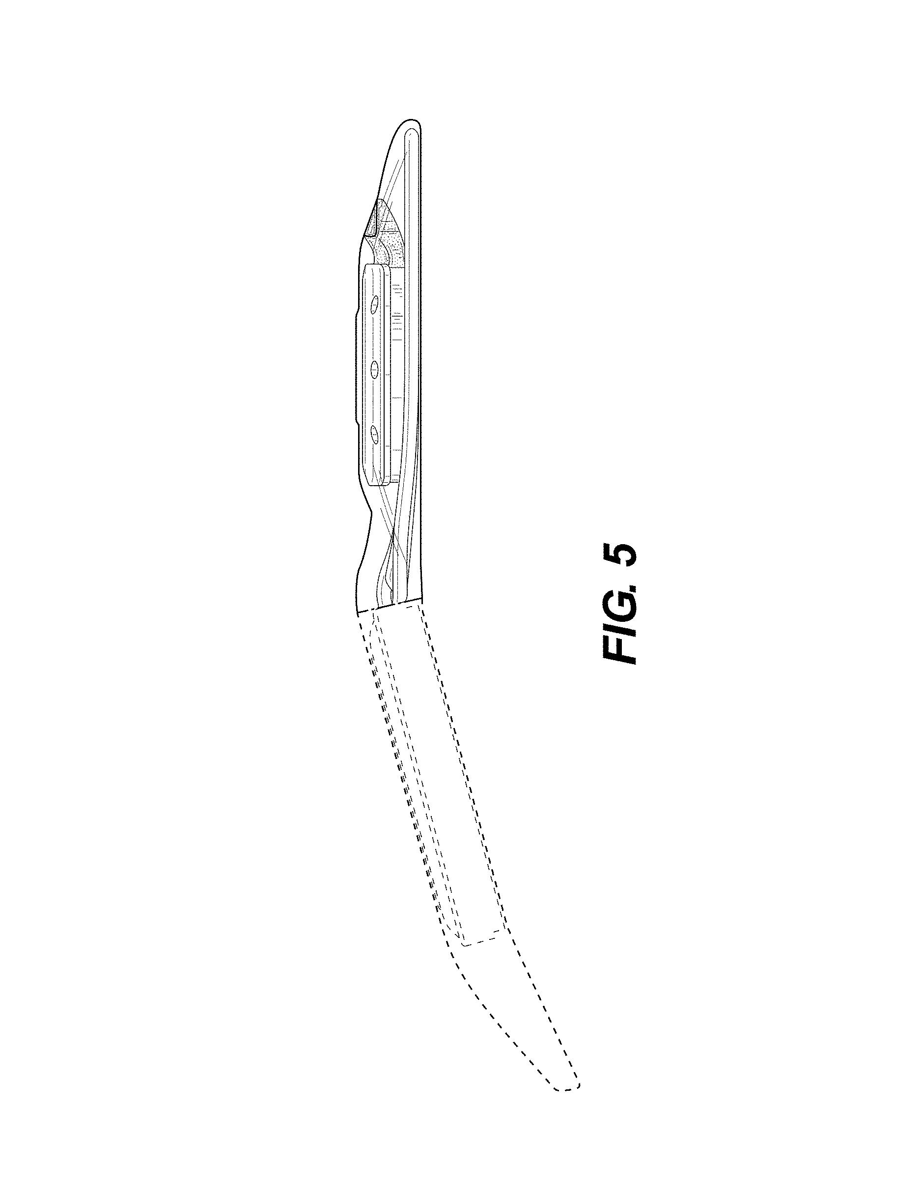
FIG. 5 is a right side view thereof;
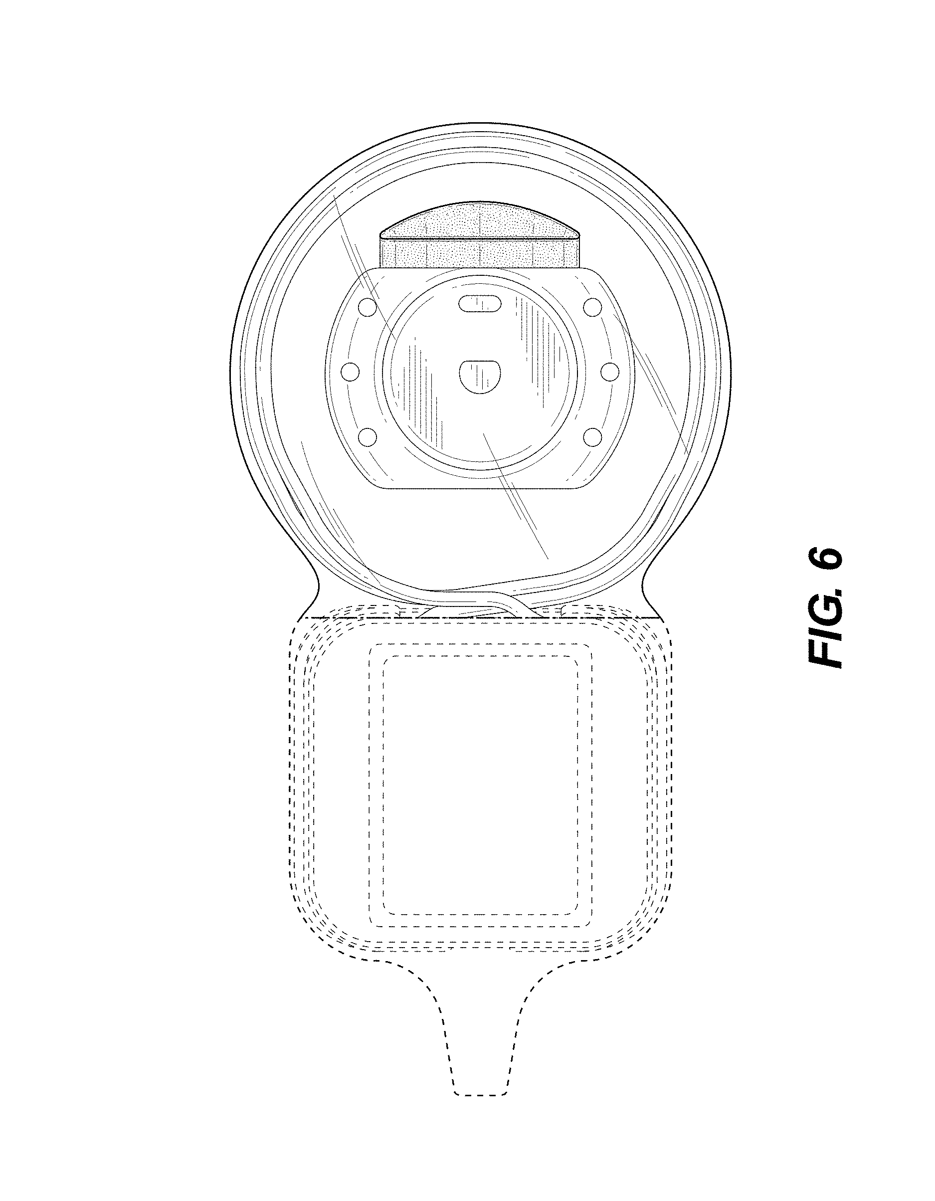
FIG. 6 is a front elevation view thereof;
FIG. 7 is rear elevation view thereof;
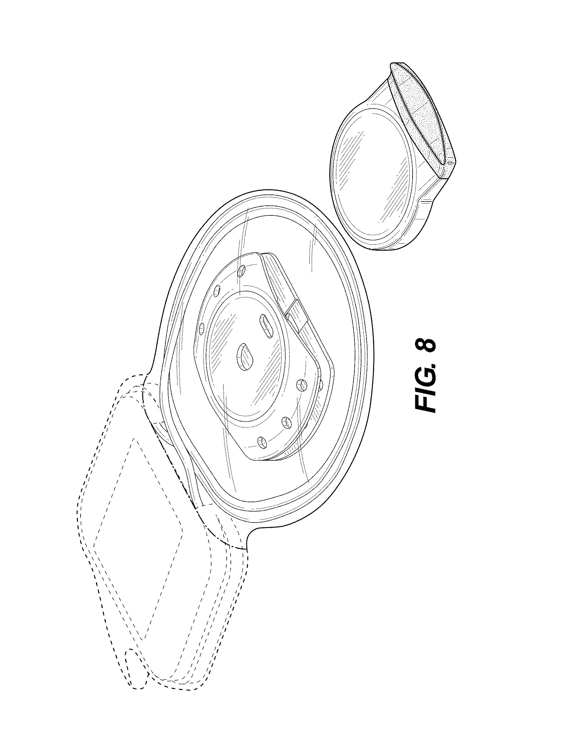
FIG. 8 is a top, front, right perspective view thereof in an alternate configuration with the magnet in a removed position;
FIG. 9 is a top plan view of the magnet;
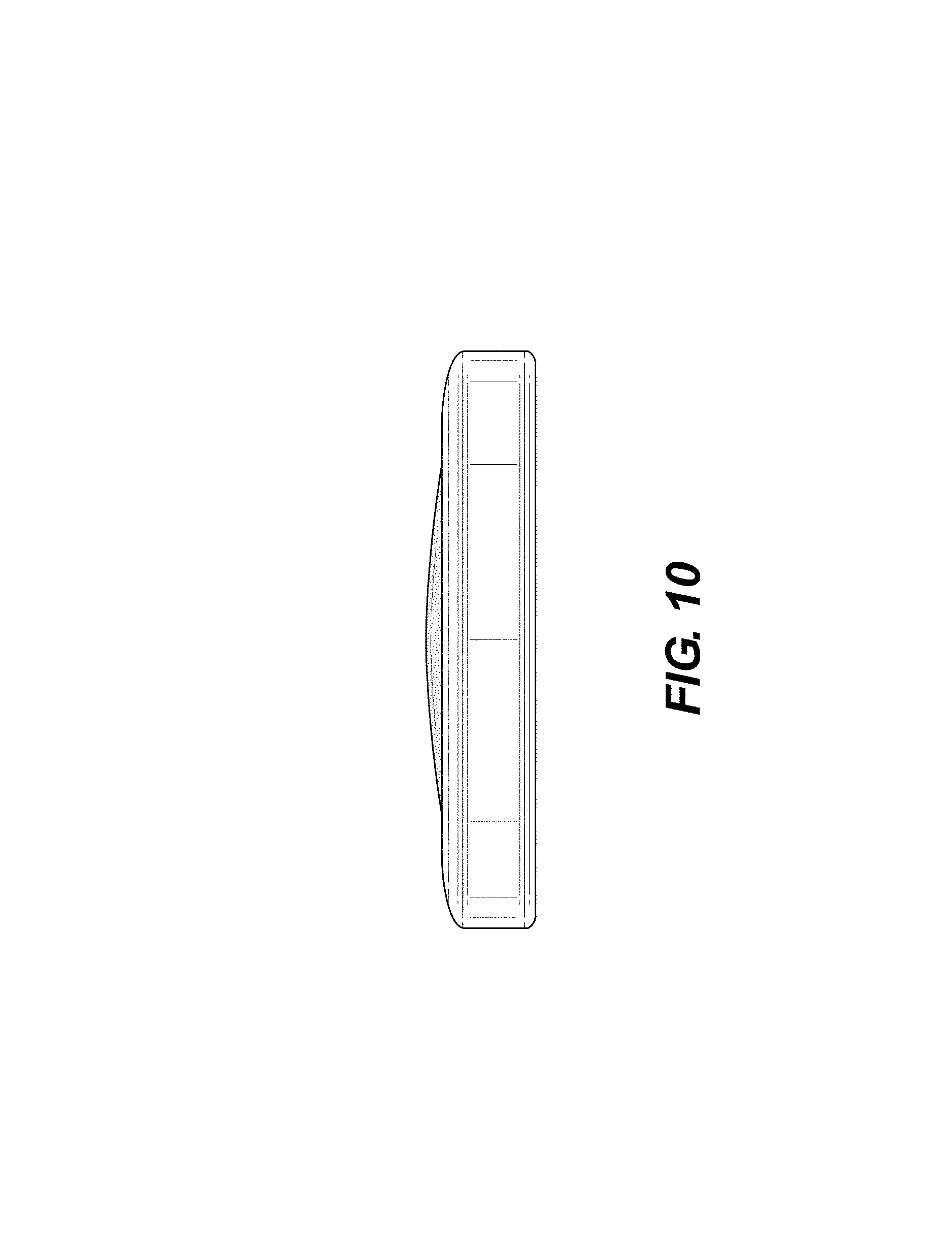
FIG. 10 is a bottom plan view of the magnet;
FIG. 11 is a right side view of the magnet, with the left side view being a mirror image thereof;
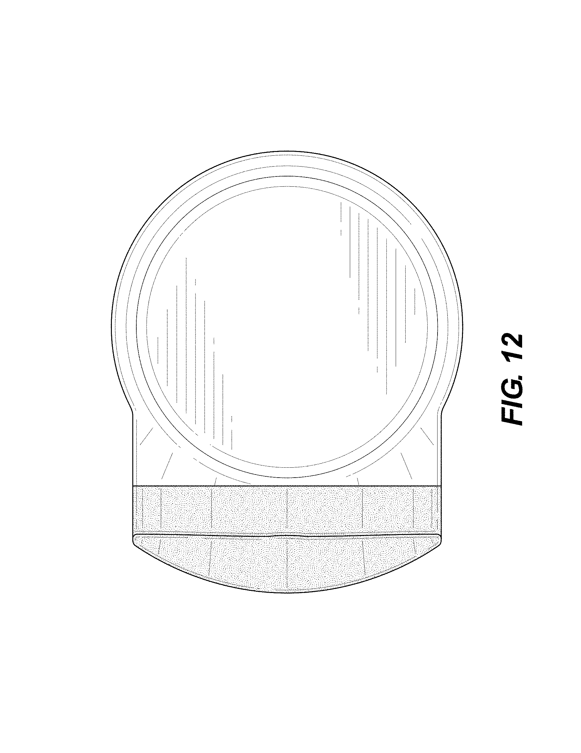
FIG. 12 is a front elevation view of the magnet; and,
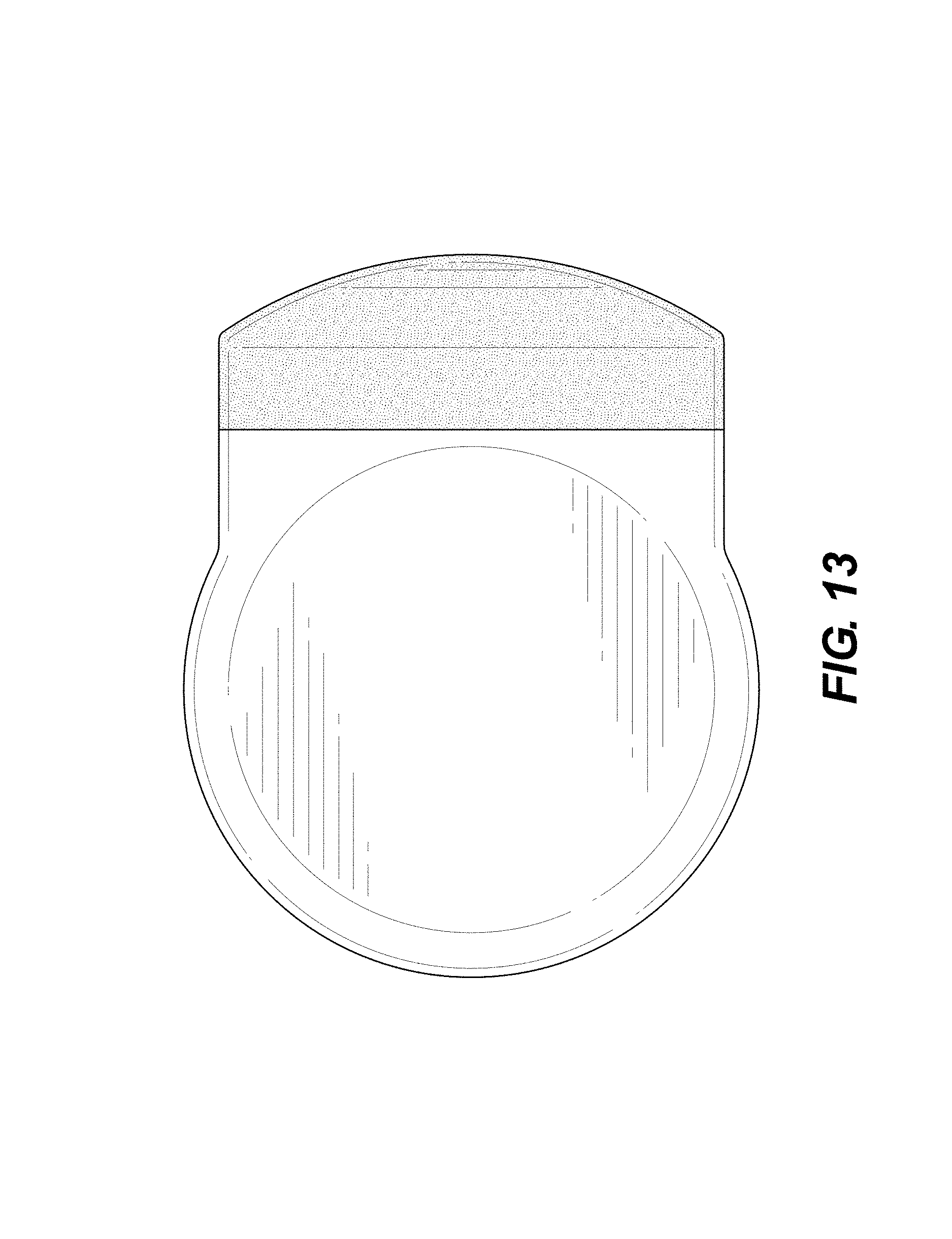
FIG. 13 is a rear elevation view of the magnet.
The uneven length broken lines illustrate the boundary of the claimed design, and form no part thereof. The even length broken lines shown in the drawings illustrate portions of the cassette with magnet that form no part of the claimed design.
Contrast in materials in FIGS. 1-13 is shown using line shading on some surfaces and stippling shading on others.
* * * * *
D00000
D00001
D00002
D00003
D00004
D00005
D00006
D00007
D00008
D00009
D00010
D00011
D00012
D00013
XML
uspto.report is an independent third-party trademark research tool that is not affiliated, endorsed, or sponsored by the United States Patent and Trademark Office (USPTO) or any other governmental organization. The information provided by uspto.report is based on publicly available data at the time of writing and is intended for informational purposes only.
While we strive to provide accurate and up-to-date information, we do not guarantee the accuracy, completeness, reliability, or suitability of the information displayed on this site. The use of this site is at your own risk. Any reliance you place on such information is therefore strictly at your own risk.
All official trademark data, including owner information, should be verified by visiting the official USPTO website at www.uspto.gov. This site is not intended to replace professional legal advice and should not be used as a substitute for consulting with a legal professional who is knowledgeable about trademark law.