Cylinder support system
Rike
U.S. patent number D849,662 [Application Number D/641,843] was granted by the patent office on 2019-05-28 for cylinder support system. This patent grant is currently assigned to WORTHINGTON INDUSTRIES, INC.. The grantee listed for this patent is WORTHINGTON INDUSTRIES, INC.. Invention is credited to James B. Rike.


| United States Patent | D849,662 |
| Rike | May 28, 2019 |
Cylinder support system
Claims
CLAIM The ornamental design for a cylinder support system, as shown and described.
| Inventors: | Rike; James B. (Mooresville, IN) | ||||||||||
|---|---|---|---|---|---|---|---|---|---|---|---|
| Applicant: |
|
||||||||||
| Assignee: | WORTHINGTON INDUSTRIES, INC.
(Columbus, OH) |
||||||||||
| Appl. No.: | D/641,843 | ||||||||||
| Filed: | March 26, 2018 |
Related U.S. Patent Documents
| Application Number | Filing Date | Patent Number | Issue Date | ||
|---|---|---|---|---|---|
| 29640271 | Mar 13, 2018 | ||||
| 29565543 | May 21, 2016 | D816010 | |||
| Current U.S. Class: | D12/223; D8/396; D12/218 |
| Current International Class: | 1206 |
| Field of Search: | ;D15/5 ;D23/393 ;D12/223,217,220,95,218,181,96,97 ;D8/380,373,354,356,394-396,349,363,355,364,366,371,381 |
References Cited [Referenced By]
U.S. Patent Documents
| 845578 | February 1907 | Austin |
| 2357148 | August 1944 | Turner |
| 2410182 | October 1946 | Prior |
| D162118 | February 1951 | Bausenbach |
| D196427 | October 1963 | Anderson et al. |
| 3227410 | January 1966 | McCuen |
| D204313 | April 1966 | Engman et al. |
| D211163 | May 1968 | Mendez |
| D244255 | May 1977 | Snyder |
| D253091 | October 1979 | Fritz |
| D273606 | April 1984 | Landry |
| D294994 | March 1988 | Burgett |
| 4925235 | May 1990 | Fingerle |
| 5054799 | October 1991 | Fingerle |
| RE33934 | May 1992 | Oetiker |
| 5810309 | September 1998 | Augustine |
| D414405 | September 1999 | Tompkins |
| 5996207 | December 1999 | Brown et al. |
| 6029989 | February 2000 | Stuart |
| 6042071 | March 2000 | Watanabe |
| 6053533 | April 2000 | Osborn |
| D442538 | May 2001 | Wagner |
| 6257360 | July 2001 | Wozniak et al. |
| 6347678 | February 2002 | Osborn |
| 6402198 | June 2002 | Gollungberg |
| 6634321 | October 2003 | Hussain et al. |
| 7117896 | October 2006 | Eberling |
| 7305836 | December 2007 | Egan |
| D591324 | April 2009 | Sukhov |
| D632555 | February 2011 | Sarkissian |
| D646214 | February 2011 | Sarkissian |
| D646618 | October 2011 | Mulanon |
| D646619 | October 2011 | Mulanon |
| D655669 | March 2012 | Matijevich |
| D704900 | May 2014 | Childs et al. |
| D720655 | January 2015 | Maiorana |
| 8944469 | February 2015 | Mulanon |
| 9033178 | May 2015 | White |
| 9057483 | June 2015 | Espinosa-Loza et al. |
| 9120372 | September 2015 | Sloan |
| 9145052 | September 2015 | De Biasi |
| 9193261 | November 2015 | Sloan et al. |
| 9217519 | December 2015 | Masters et al. |
| 9217538 | December 2015 | Griffith et al. |
| 9234625 | January 2016 | Sirosh |
| 9249931 | February 2016 | Morales et al. |
| 9266642 | February 2016 | Prakash et al. |
| 9434333 | September 2016 | Sloan |
| D782931 | April 2017 | Takakuwa |
| 9756780 | September 2017 | Blunier |
| 9908406 | March 2018 | Rike |
| 9909535 | March 2018 | Sirosh |
| D819778 | June 2018 | Polacek |
| 2002/0005312 | January 2002 | Gollungberg |
| 2003/0001059 | January 2003 | Kim et al. |
| 2003/0029977 | February 2003 | Kim |
| 2006/0006635 | January 2006 | Sonderegger |
| 2006/0061081 | March 2006 | Kresse et al. |
| 2007/0170180 | July 2007 | Watanabe |
| 2009/0114784 | May 2009 | Tam |
| 2010/0320727 | December 2010 | Haut |
| 2013/0069357 | March 2013 | Green |
| 2013/0292387 | November 2013 | Spencer |
| 2013/0306695 | November 2013 | Guaresimo |
| 2014/0174159 | June 2014 | Kim |
| 2014/0175782 | June 2014 | Sloan |
| 2015/0096977 | April 2015 | Sirosh et al. |
| 2016/0082910 | March 2016 | Sloan et al. |
| 2016/0332514 | November 2016 | Arold et al. |
| 2017/0057348 | March 2017 | Arold et al. |
| 2017/0101003 | April 2017 | Zimmerman |
| 2017/0334288 | November 2017 | Rike |
| 199623721 | Aug 1996 | WO | |||
| 200168446 | Sep 2001 | WO | |||
| 2011152733 | Dec 2011 | WO | |||
| 2013168080 | Nov 2013 | WO | |||
| 2014149060 | Sep 2014 | WO | |||
| 2015014517 | Feb 2015 | WO | |||
| 2015175842 | Nov 2015 | WO | |||
Assistant Examiner: Aman; Ania
Attorney, Agent or Firm: Tucker Ellis LLP Garritano; Carlos
Description
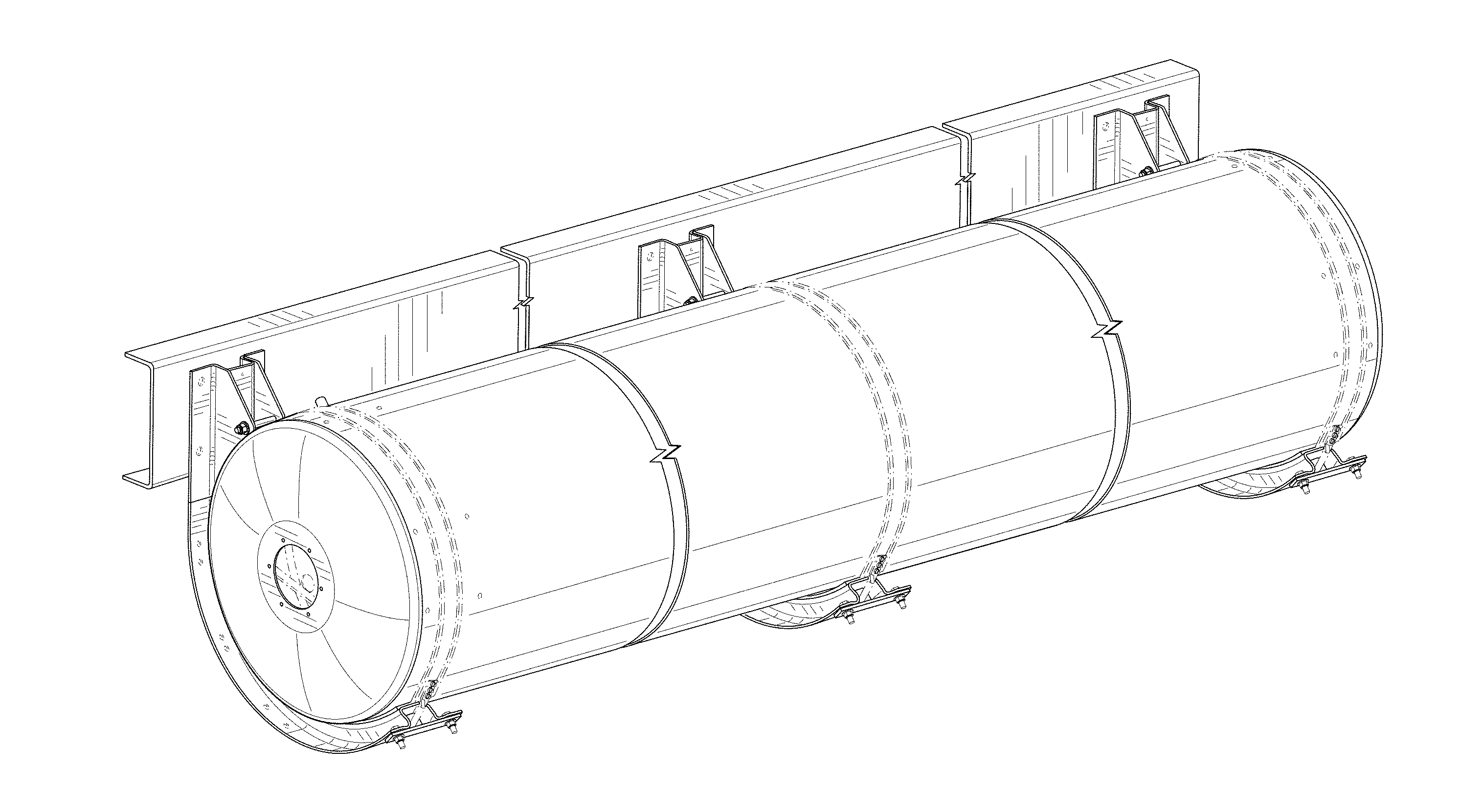
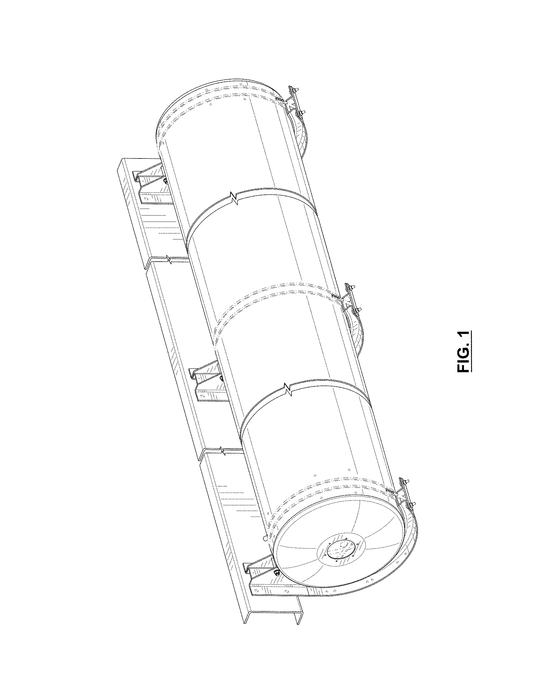
FIG. 1 is a perspective view of a cylinder support system showing our new design;
FIG. 2 is a left side view of the cylinder support system illustrated in FIG. 1 with the opposite side being a mirror-image thereof;
FIG. 3 is a front view of the cylinder support system illustrated in FIG. 1;
FIG. 4 is a right side view of the cylinder support system illustrated in FIG. 1;
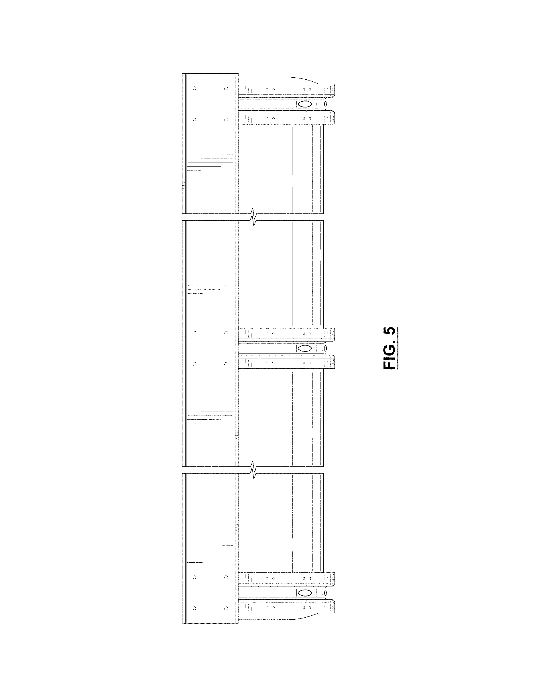
FIG. 5 is a rear view of the cylinder support system illustrated in FIG. 1;
FIG. 6 is a top view of the cylinder support system illustrated in FIG. 1; and,
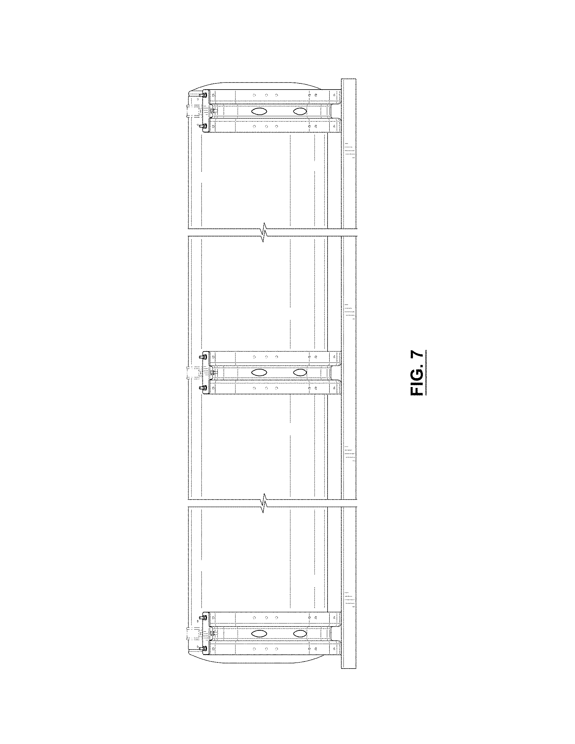
FIG. 7 is a bottom view of the cylinder support system illustrated in FIG. 1.
In the drawings, the broken lines depict unclaimed environmental subject matter only and form no part of the claimed design.
The cut away portions in the drawings indicate that the appearance of any portion of the article between the cut away lines forms no part of the claimed design.
* * * * *
D00000
D00001
D00002
D00003
D00004
D00005
D00006
D00007
XML
uspto.report is an independent third-party trademark research tool that is not affiliated, endorsed, or sponsored by the United States Patent and Trademark Office (USPTO) or any other governmental organization. The information provided by uspto.report is based on publicly available data at the time of writing and is intended for informational purposes only.
While we strive to provide accurate and up-to-date information, we do not guarantee the accuracy, completeness, reliability, or suitability of the information displayed on this site. The use of this site is at your own risk. Any reliance you place on such information is therefore strictly at your own risk.
All official trademark data, including owner information, should be verified by visiting the official USPTO website at www.uspto.gov. This site is not intended to replace professional legal advice and should not be used as a substitute for consulting with a legal professional who is knowledgeable about trademark law.