Cutting tool for tree pruning
Heine , et al.
U.S. patent number D848,229 [Application Number D/602,503] was granted by the patent office on 2019-05-14 for cutting tool for tree pruning. This patent grant is currently assigned to FISKARS FINLAND OY AB. The grantee listed for this patent is Fiskars Finland Oy Ab. Invention is credited to Mikko Heine, Kari Kunnas, Sami Lyytikainen, Petteri Masalin.


View All Diagrams
| United States Patent | D848,229 |
| Heine , et al. | May 14, 2019 |
Cutting tool for tree pruning
Claims
CLAIM We claim the ornamental design for a cutting tool for tree pruning, as shown and described.
| Inventors: | Heine; Mikko (Helsinki, FI), Kunnas; Kari (Helsinki, FI), Lyytikainen; Sami (Helsinki, FI), Masalin; Petteri (Helsinki, FI) | ||||||||||
|---|---|---|---|---|---|---|---|---|---|---|---|
| Applicant: |
|
||||||||||
| Assignee: | FISKARS FINLAND OY AB
(Helsinki, FI) |
||||||||||
| Appl. No.: | D/602,503 | ||||||||||
| Filed: | May 1, 2017 |
Foreign Application Priority Data
| Nov 7, 2016 [EM] | 003451434 | |||
| Current U.S. Class: | D8/5 |
| Current International Class: | 0801 |
| Field of Search: | ;D8/1,4,5,51,52,53,54,56,58,107 |
References Cited [Referenced By]
U.S. Patent Documents
| 875159 | December 1907 | Crow |
| 967502 | August 1910 | Cooper |
| 1557853 | October 1925 | Lipscomb |
| 1697749 | January 1929 | Billings |
| 2795034 | June 1957 | Forgette |
| D295017 | April 1988 | Evenson |
| 4949461 | August 1990 | van der Merwe |
| D321816 | November 1991 | Fushiya |
| D329796 | September 1992 | Olson et al. |
| D367416 | February 1996 | Gustafson et al. |
| D379422 | May 1997 | Yates et al. |
| 5950315 | September 1999 | Linden |
| D429130 | August 2000 | Fallandy |
| D487386 | March 2004 | Clivio |
| 6748663 | June 2004 | Linden |
| D494039 | August 2004 | Tsai |
| D519821 | May 2006 | Tsai |
| D551530 | September 2007 | Hirsch |
| D570659 | June 2008 | Lin |
| D592482 | May 2009 | Gregory |
| D599172 | September 2009 | Wang et al. |
| D599626 | September 2009 | Wang et al. |
| D630927 | January 2011 | Huang |
| D632858 | February 2011 | Sgroi et al. |
| D636956 | April 2011 | Sgroi et al. |
| 8069573 | December 2011 | Wu |
| D655815 | March 2012 | Miller et al. |
| 8683704 | April 2014 | Scott |
| D743770 | November 2015 | Hsieh |
| D754517 | April 2016 | Henderson |
| D773276 | December 2016 | Ou |
| D806489 | January 2018 | Fancelli |
| 9872591 | January 2018 | Casavan |
| 2004/0031156 | February 2004 | Linden |
| 2004/0055164 | March 2004 | Molins |
| 2004/0194320 | October 2004 | Hsieh |
| 2006/0225289 | October 2006 | Glodowski |
| 2009/0038162 | February 2009 | Shan |
| 2010/0186559 | July 2010 | Pell |
| 2010/0199502 | August 2010 | Linden |
| 2011/0107606 | May 2011 | Shan |
| 2011/0271532 | November 2011 | Wu |
| 2012/0167396 | July 2012 | Wu |
| 2017/0099780 | April 2017 | Linden |
Assistant Examiner: Price; Ieisha N
Attorney, Agent or Firm: Leason Ellis LLP
Description
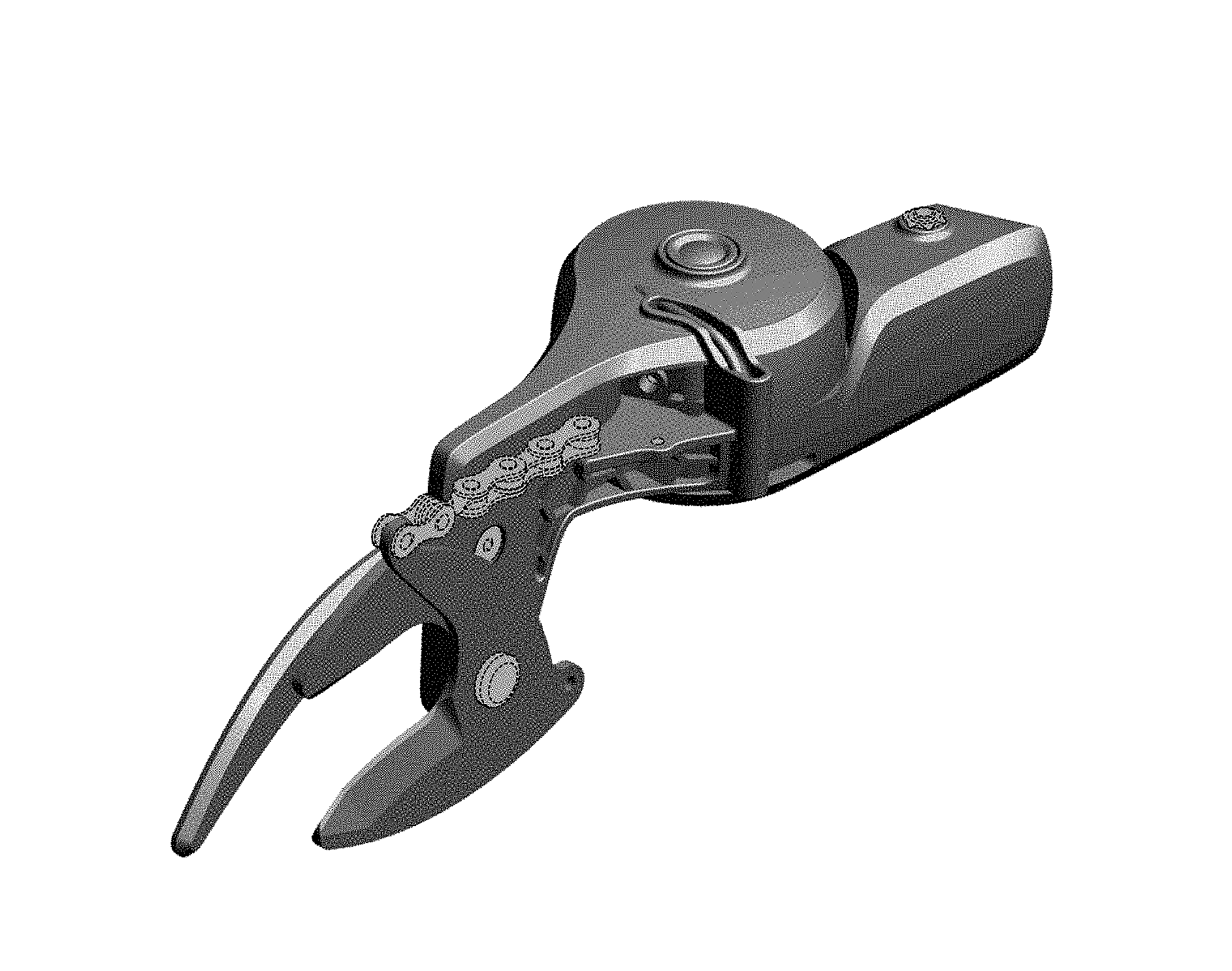
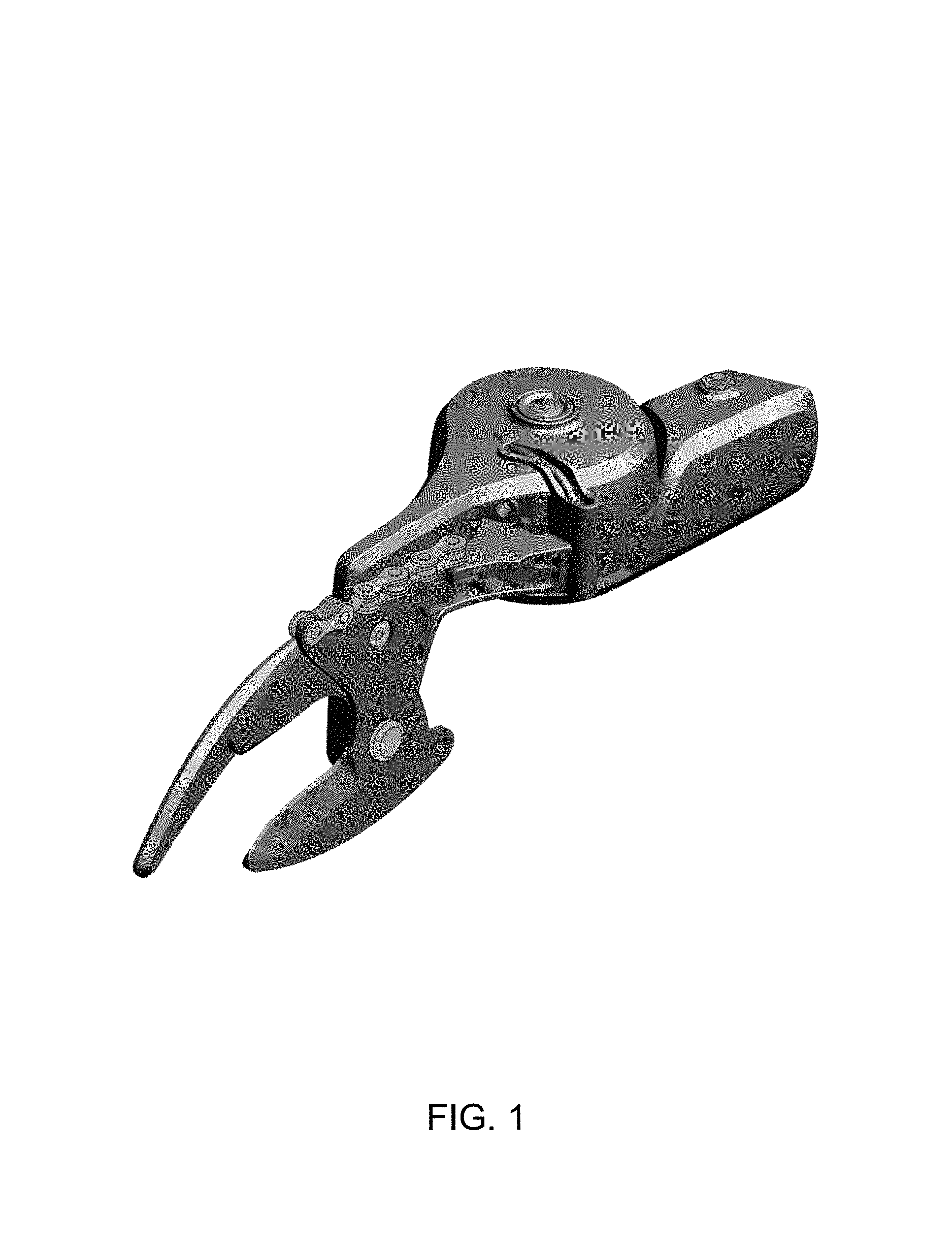
FIG. 1 is a top perspective view of an embodiment of the claimed design;
FIG. 2 is front view thereof;
FIG. 3 is a rear view thereof;
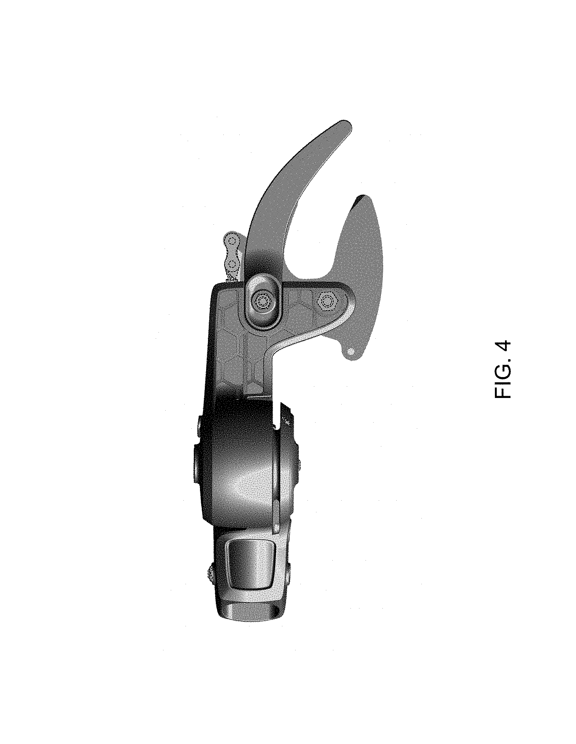
FIG. 4 is a left side view thereof;
FIG. 5 is a right side view thereof;
FIG. 6 is a top view thereof;
FIG. 7 is a bottom view thereof;
FIG. 8 is a top perspective view of the second embodiment of the claimed design;
FIG. 9 is front view thereof;
FIG. 10 is a rear view thereof;
FIG. 11 is a left side view thereof;
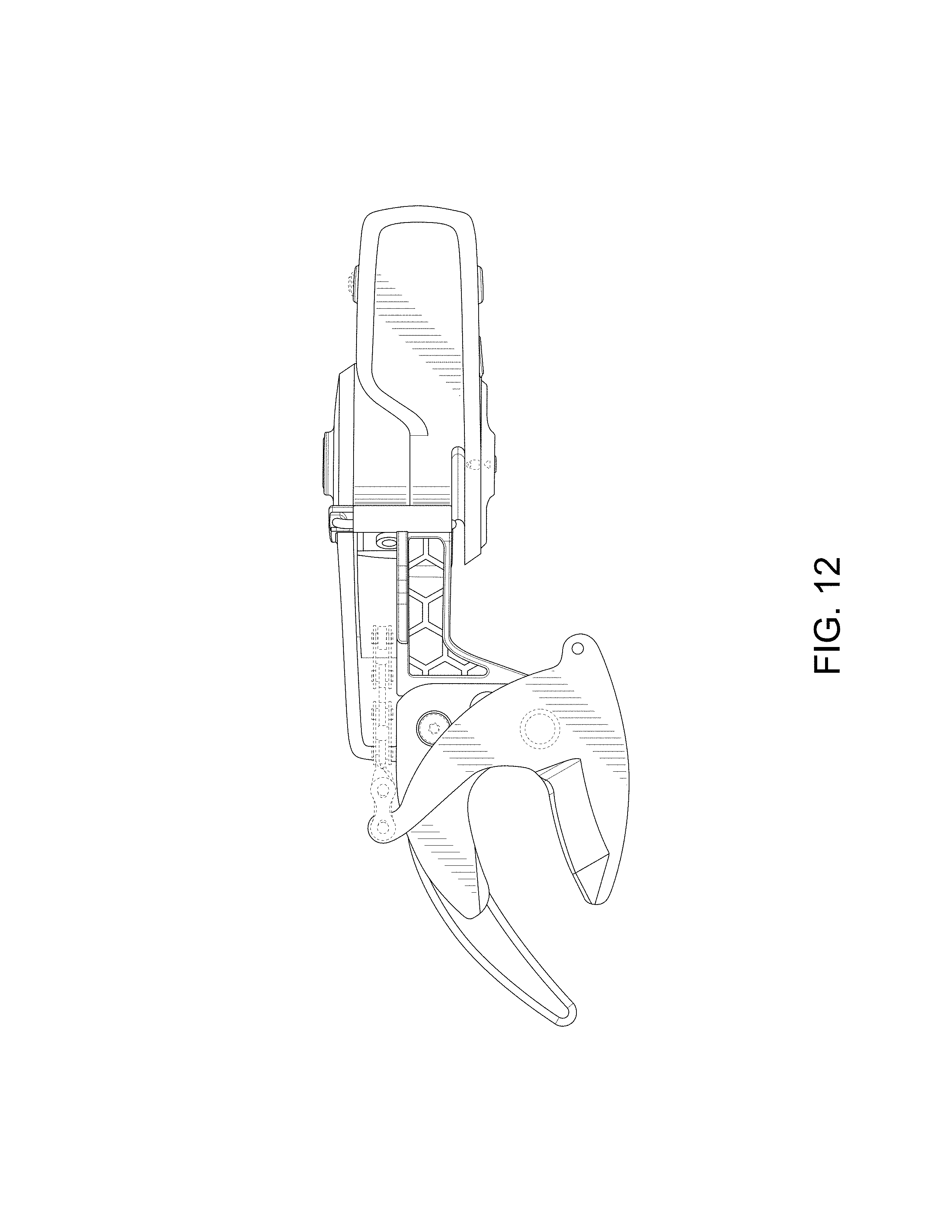
FIG. 12 is a right side view thereof;
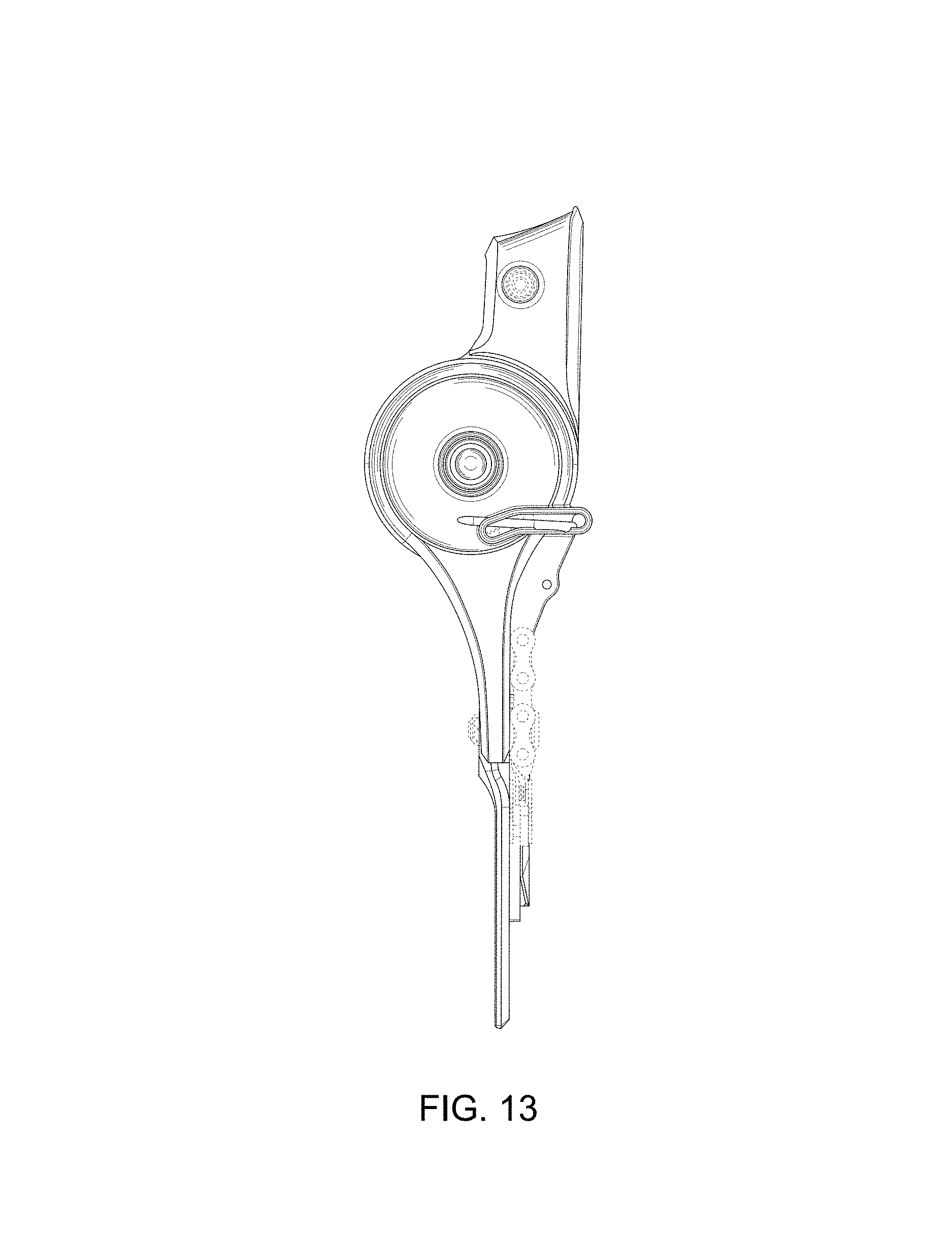
FIG. 13 is a top view thereof; and,
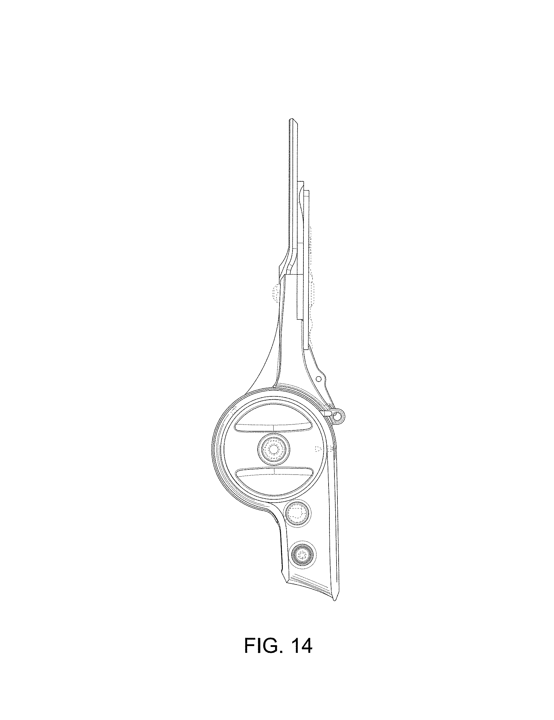
FIG. 14 is a bottom view thereof.
Any portion of the article depicted in broken lines forms no part of the claimed design.
* * * * *
D00000
D00001
D00002
D00003
D00004
D00005
D00006
D00007
D00008
D00009
D00010
D00011
D00012
XML
uspto.report is an independent third-party trademark research tool that is not affiliated, endorsed, or sponsored by the United States Patent and Trademark Office (USPTO) or any other governmental organization. The information provided by uspto.report is based on publicly available data at the time of writing and is intended for informational purposes only.
While we strive to provide accurate and up-to-date information, we do not guarantee the accuracy, completeness, reliability, or suitability of the information displayed on this site. The use of this site is at your own risk. Any reliance you place on such information is therefore strictly at your own risk.
All official trademark data, including owner information, should be verified by visiting the official USPTO website at www.uspto.gov. This site is not intended to replace professional legal advice and should not be used as a substitute for consulting with a legal professional who is knowledgeable about trademark law.