Terminal
Yeruva , et al.
U.S. patent number D844,046 [Application Number D/590,929] was granted by the patent office on 2019-03-26 for terminal. This patent grant is currently assigned to Clover Network, Inc.. The grantee listed for this patent is Clover Network, Inc.. Invention is credited to John Daniel Beatty, Eric David Fuhs, Christopher Loew, David Frederick Lyons, Sam Niansheng Qiu, Leonard Robert Speiser, Siva Raja Sekhar Reddy Yeruva.


| United States Patent | D844,046 |
| Yeruva , et al. | March 26, 2019 |
Terminal
Claims
CLAIM The ornamental design for a terminal, as shown and described.
| Inventors: | Yeruva; Siva Raja Sekhar Reddy (Menlo Park, CA), Qiu; Sam Niansheng (Palo Alto, CA), Lyons; David Frederick (Palo Alto, CA), Loew; Christopher (Palo Alto, CA), Fuhs; Eric David (Sunnvyale, CA), Beatty; John Daniel (Emerald Hills, CA), Speiser; Leonard Robert (Los Altos, CA) | ||||||||||
|---|---|---|---|---|---|---|---|---|---|---|---|
| Applicant: |
|
||||||||||
| Assignee: | Clover Network, Inc.
(Sunnyvale, CA) |
||||||||||
| Appl. No.: | D/590,929 | ||||||||||
| Filed: | January 13, 2017 |
| Current U.S. Class: | D18/4.5; D18/4.6 |
| Current International Class: | 1801 |
| Field of Search: | ;D18/4.4,4.5,4.6,2,11,50,14,19-21,54,99 ;D14/300,307,338,339,341,356,357,383,385,386,388,426,453-455,496,507,509,510,154,155,158,168,218,225,226,248,299,314,328,332,335,900,902 ;D10/46,61,62,70,104.1,104.2,106.2,106.6,65,66 ;D20/1 ;D13/168 |
References Cited [Referenced By]
U.S. Patent Documents
| D350555 | September 1994 | Field |
| D375735 | November 1996 | Tochishita |
| D388826 | January 1998 | Jones-Fenleigh |
| D410441 | June 1999 | Lin |
| D436951 | January 2001 | Andresen |
| D506767 | June 2005 | Imai |
| D510577 | October 2005 | Jobs |
| D529910 | October 2006 | Ota |
| D635975 | April 2011 | Seo |
| D682830 | May 2013 | Taunay da Graca Couto |
| D694206 | November 2013 | Seo |
| D707288 | June 2014 | Branck |
| D709069 | July 2014 | Cruz |
| D713447 | September 2014 | Balar |
| D720000 | December 2014 | Lyons |
| D724582 | March 2015 | Kim |
| D734280 | July 2015 | Choi |
| D735802 | August 2015 | Lyons et al. |
| D746902 | January 2016 | Lyons |
| D761350 | July 2016 | Beatty |
| D761899 | July 2016 | Beatty |
| D778982 | February 2017 | Beatty |
| D792392 | July 2017 | Sharma |
| D794629 | August 2017 | Jiang |
| D814559 | April 2018 | Oross |
| D823303 | July 2018 | Jiang |
| 2015/0241919 | August 2015 | Beatty |
| 2016/0070964 | March 2016 | Conrad |
| 2018/0033255 | February 2018 | Beatty |
Attorney, Agent or Firm: Daylight Law, P.C.
Description
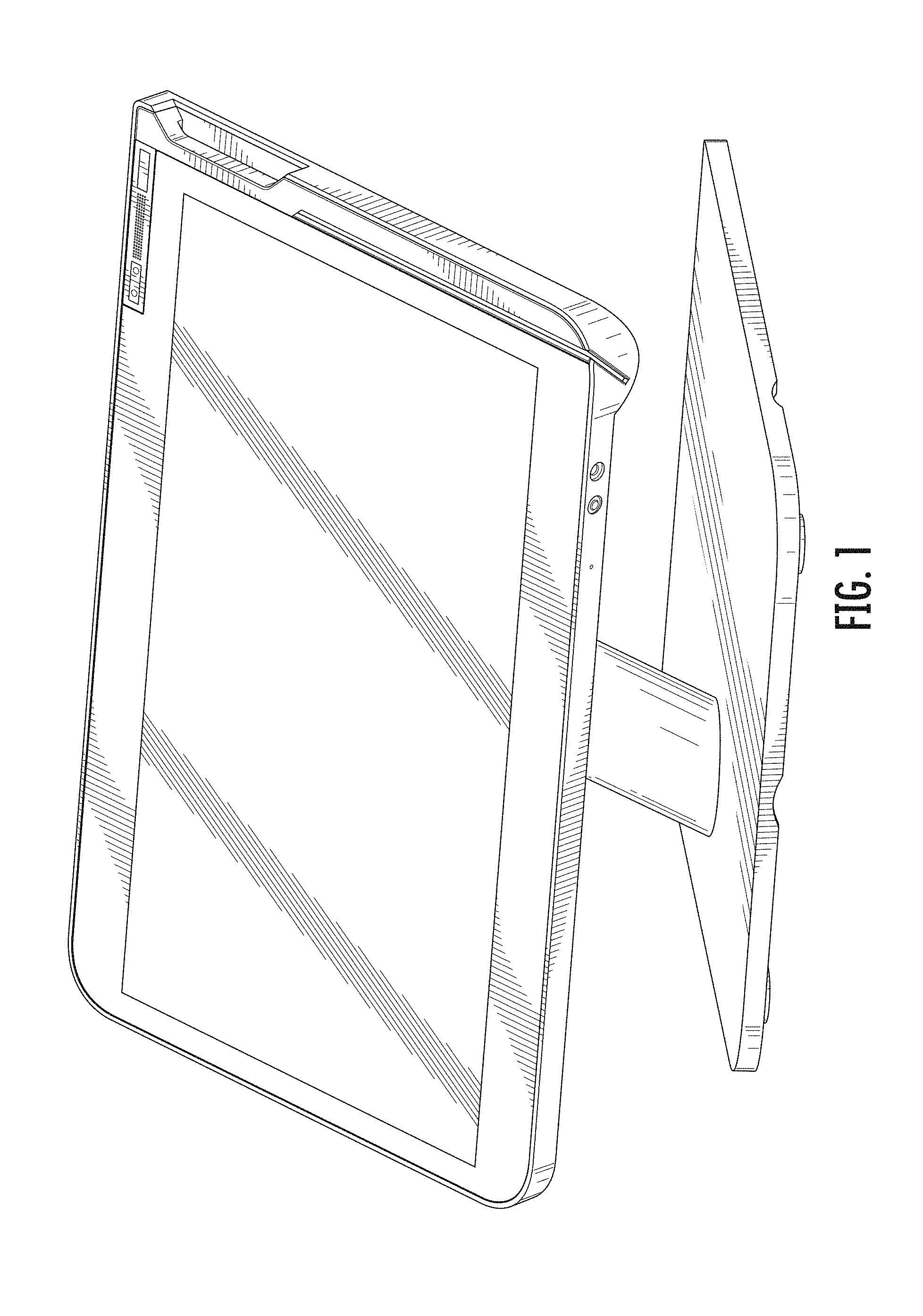
FIG. 1 is a perspective view of a terminal;
FIG. 2 is a front view of the design of FIG. 1;
FIG. 3 is a rear view of the design of FIG. 1;
FIG. 4 is a right side view of the design of FIG. 1;
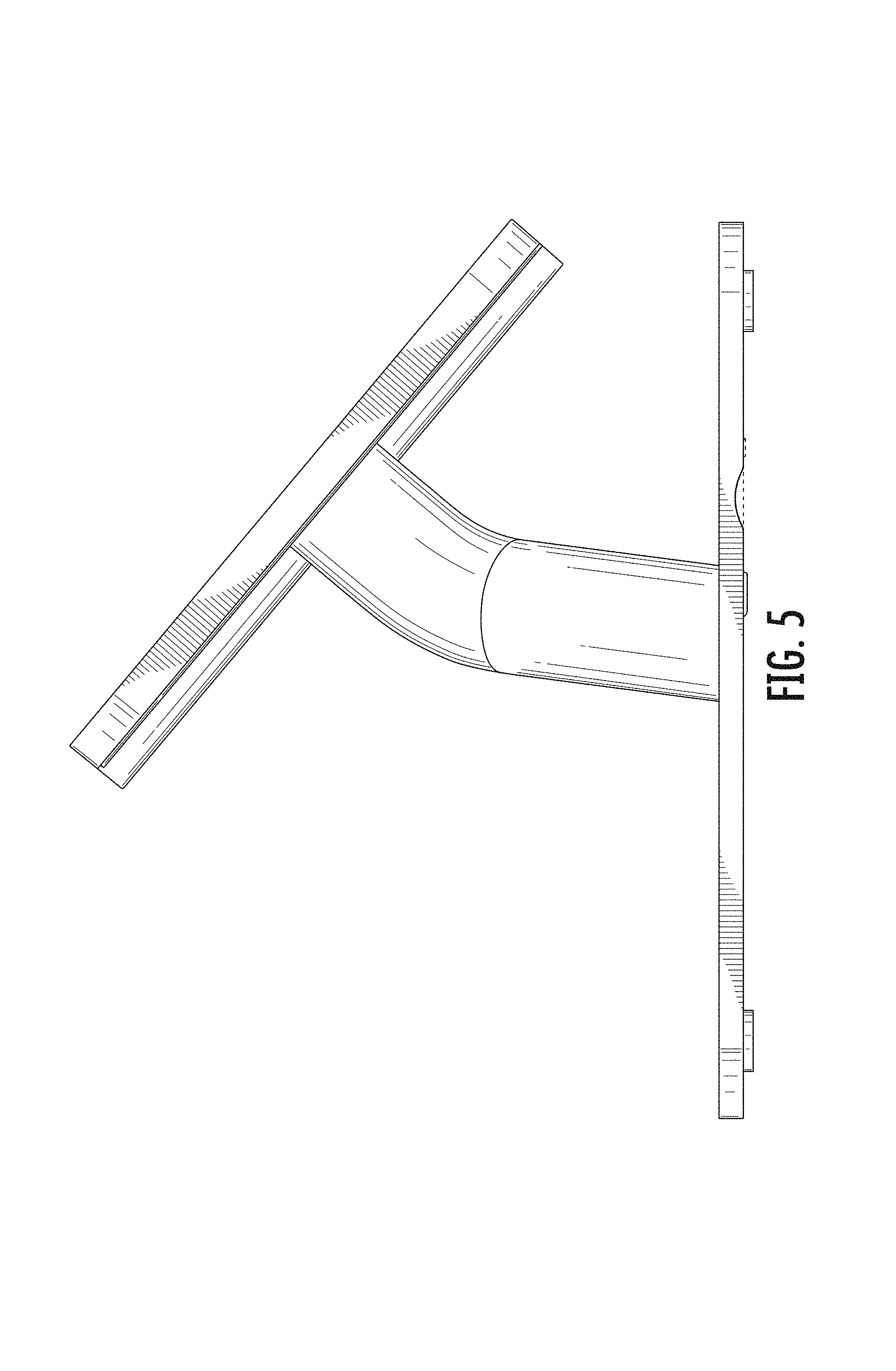
FIG. 5 is a left side view of the design of FIG. 1;
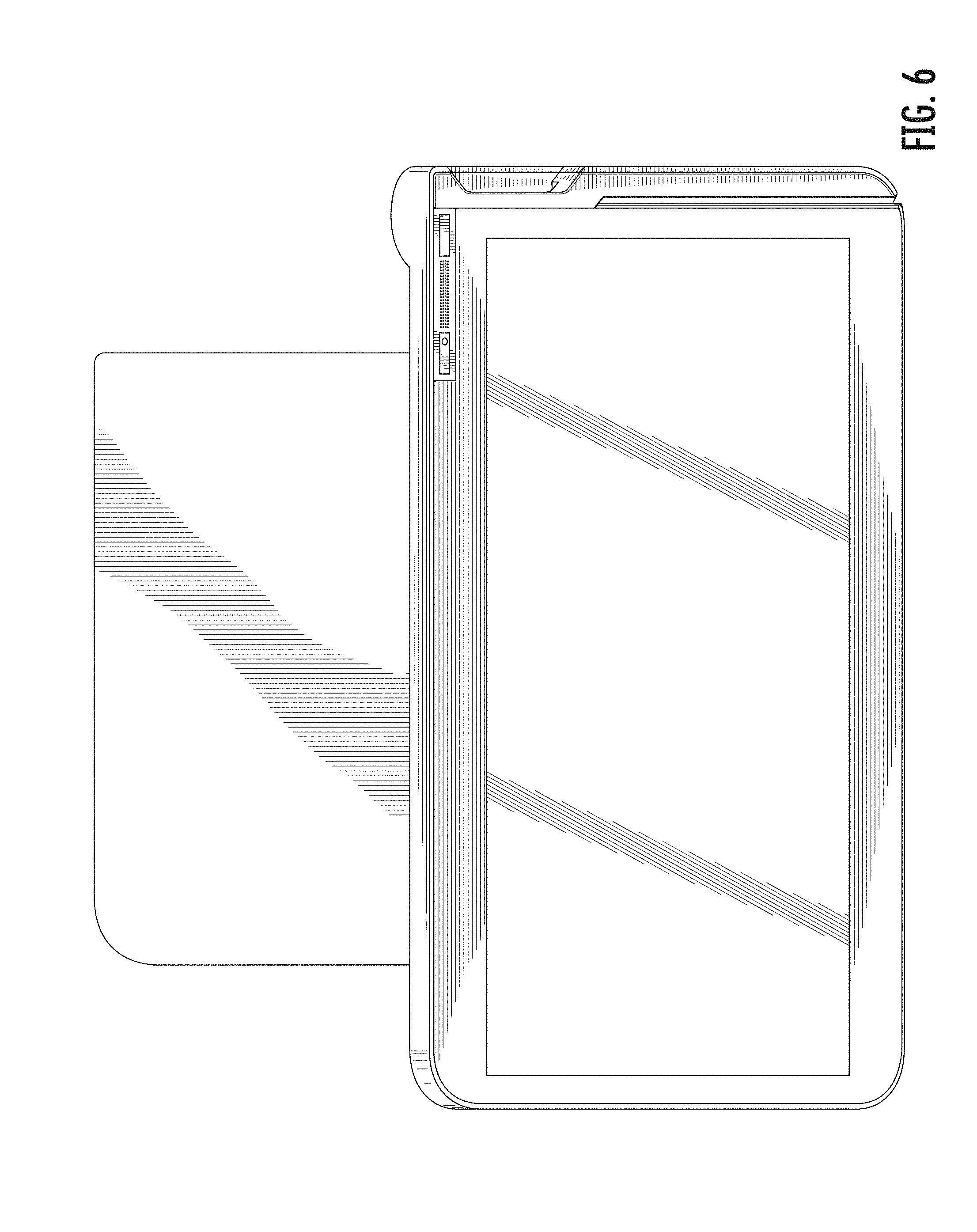
FIG. 6 is a top view of the design of FIG. 1; and,
FIG. 7 is a bottom view of the design of FIG. 1.
The broken lines in the drawings depict portions of the terminal that form no part of the claim.
* * * * *
D00000
D00001
D00002
D00003
D00004
D00005
D00006
D00007
XML
uspto.report is an independent third-party trademark research tool that is not affiliated, endorsed, or sponsored by the United States Patent and Trademark Office (USPTO) or any other governmental organization. The information provided by uspto.report is based on publicly available data at the time of writing and is intended for informational purposes only.
While we strive to provide accurate and up-to-date information, we do not guarantee the accuracy, completeness, reliability, or suitability of the information displayed on this site. The use of this site is at your own risk. Any reliance you place on such information is therefore strictly at your own risk.
All official trademark data, including owner information, should be verified by visiting the official USPTO website at www.uspto.gov. This site is not intended to replace professional legal advice and should not be used as a substitute for consulting with a legal professional who is knowledgeable about trademark law.