Heat exchanger
Szolony , et al.
U.S. patent number D842,974 [Application Number 35/503,365] was granted by the patent office on 2019-03-12 for heat exchanger. This patent grant is currently assigned to TOMTON s.r.o.. The grantee listed for this patent is TOMTON S.R.O.. Invention is credited to Ondrej Sikula, Tomas Szolony.


View All Diagrams
| United States Patent | D842,974 |
| Szolony , et al. | March 12, 2019 |
Heat exchanger
Claims
CLAIM The ornamental design for a heat exchanger, as shown and described.
| Inventors: | Szolony; Tomas (Zilina, CZ), Sikula; Ondrej (Brno, CZ) | ||||||||||
|---|---|---|---|---|---|---|---|---|---|---|---|
| Applicant: |
|
||||||||||
| Assignee: | TOMTON s.r.o. (Velke
Albrechtice, CZ) |
||||||||||
| Appl. No.: | 35/503,365 | ||||||||||
| Filed: | June 7, 2017 |
International Registration
| Int'l Reg. No. | Int'l Reg. Date | Int'l Reg. Publication Date |
Hague Int'l Filing Date |
|---|---|---|---|
| DM/096680 | Jun 7, 2017 | Jul 14, 2017 | Jun 7, 2017 |
Foreign Application Priority Data
| Feb 27, 2017 [EM] | 003771153-0001 | |||
| Feb 27, 2017 [EM] | 003771153-0002 | |||
| Feb 27, 2017 [EM] | 003771153-0003 | |||
| Feb 27, 2017 [EM] | 003771153-0004 | |||
| Current U.S. Class: | D23/323 |
| Current International Class: | 2304 |
| Field of Search: | ;D23/314,317,330,332,333,335-351,354-356,370,376,378,381,382,386,411,412,323,388,389 |
References Cited [Referenced By]
U.S. Patent Documents
| D28514 | April 1898 | Easterly |
| D74086 | December 1927 | Waters |
| D356367 | March 1995 | Kolb |
| D360258 | July 1995 | Shellenberger |
| D655728 | March 2012 | Seno |
| D719649 | December 2014 | Ainley |
| D785151 | April 2017 | Oktayer |
| 2013/0299132 | November 2013 | Guilford |
Other References
|
[Online] http://www.tomton.cz/en/product/radiator-tomton-r4/. Retrieved Oct. 13, 2018. cited by examiner. |
Primary Examiner: Pellegrini; Melanie
Attorney, Agent or Firm: Bergen; Grady K. Griggs Bergen LLP
Description
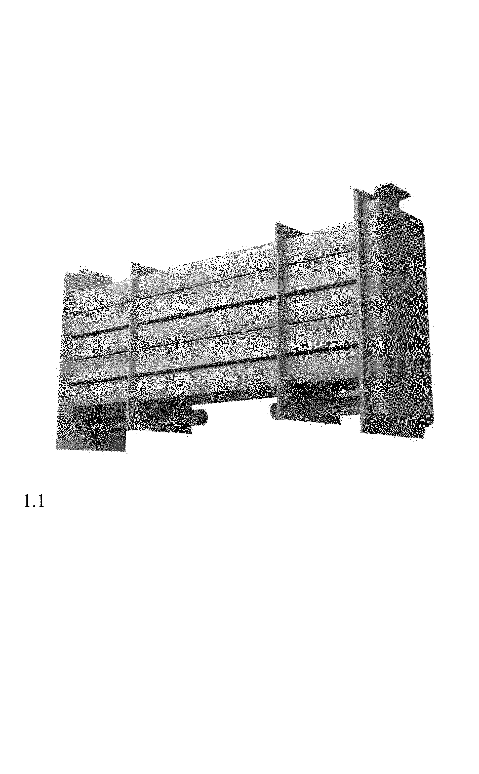
1.1 is a bottom, front, and right side perspective view of a heat exchanger;
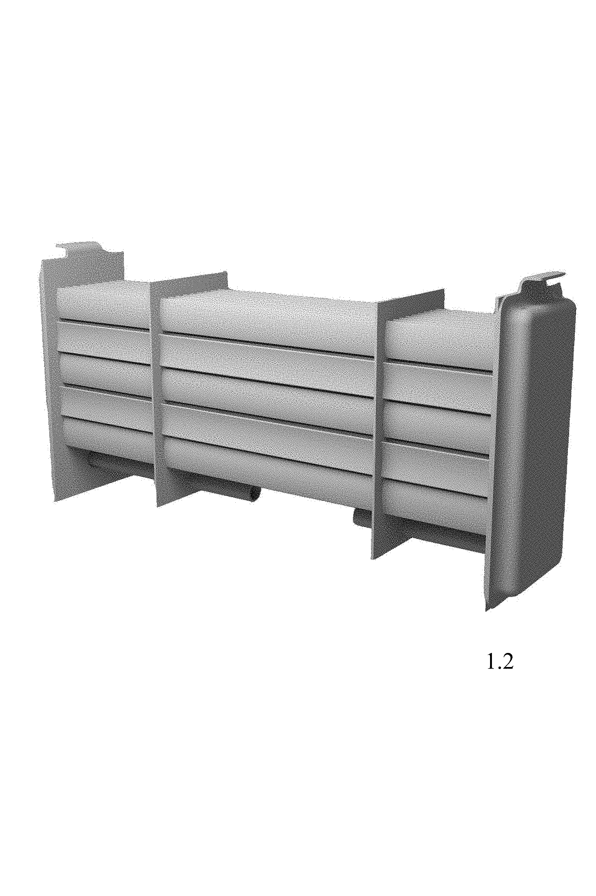
1.2 is a top, front, and right side perspective view of the heat exchanger of FIG. 1.1;
1.3 is a top, rear, and left side perspective view of the heat exchanger of FIG. 1.1 with a portion removed for completeness of the disclosure;
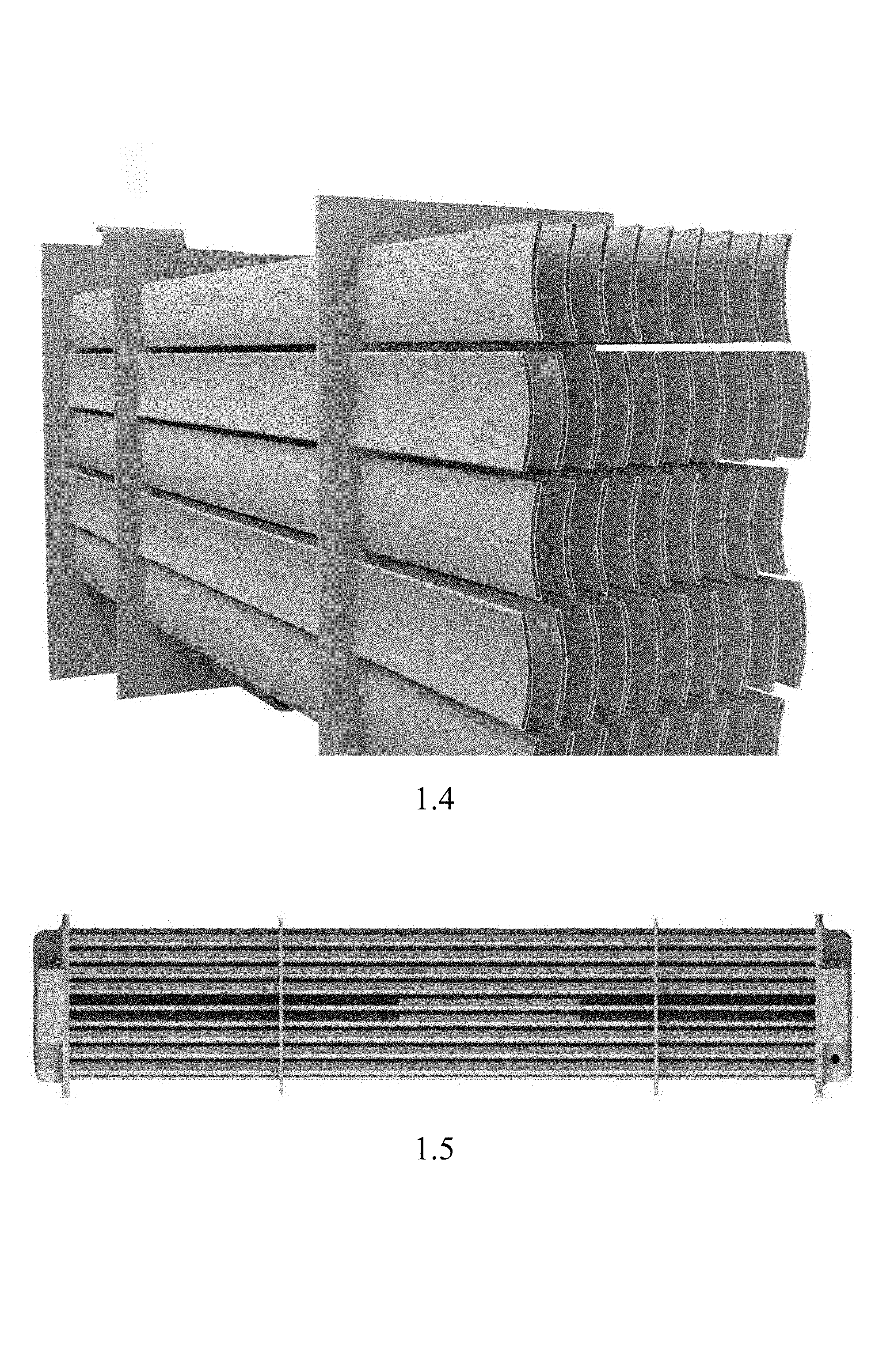
1.4 is an enlarged and partial rear and left side perspective view of the heat exchanger of FIG. 1.1 with a portion removed for completeness of the disclosure;
1.5 is a top plan view of the heat exchanger of FIGS. 1.1; and
1.6 is a left side elevational view of the heat exchanger of FIG. 1.1 with a portion removed for completeness of the disclosure;
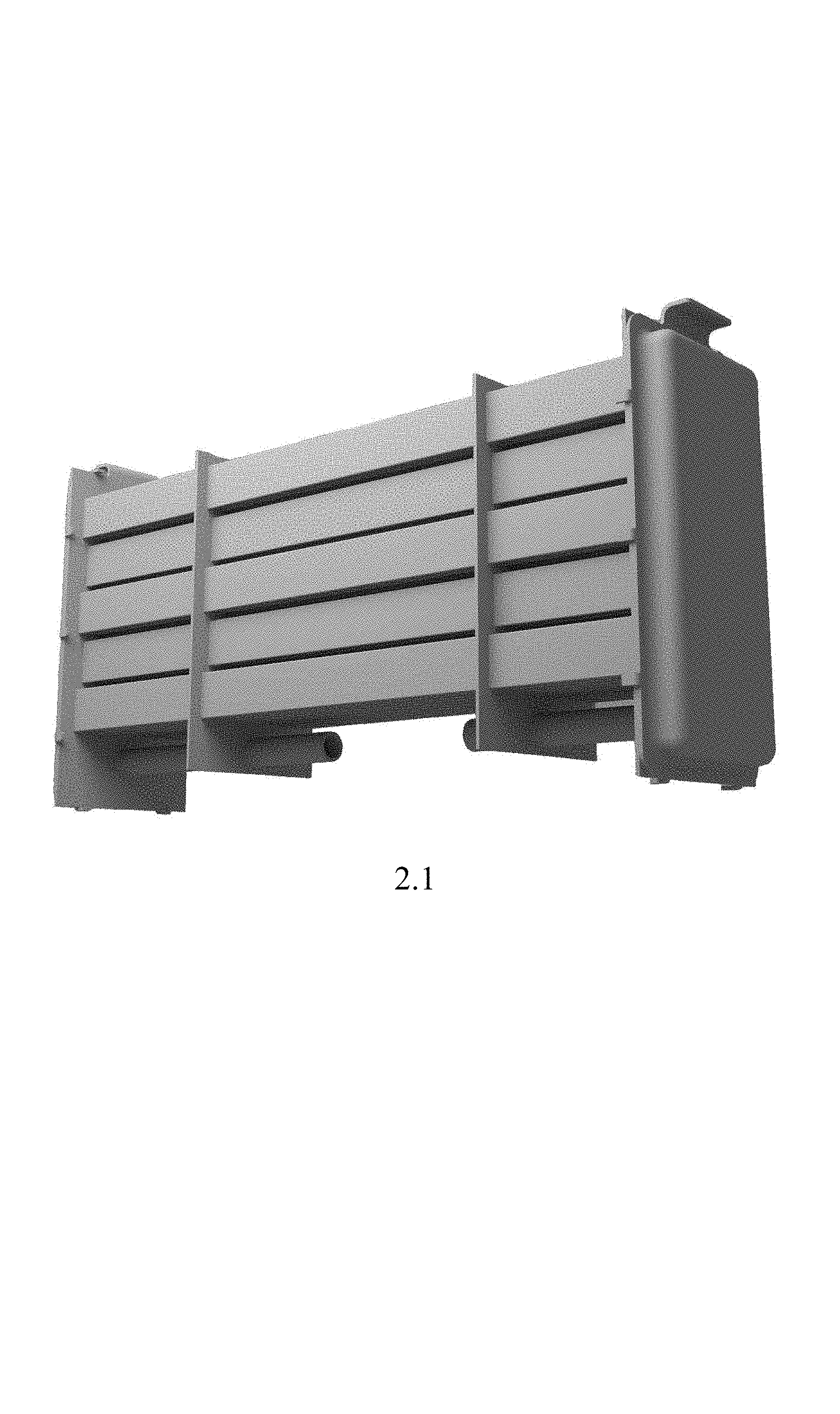
2.1 is a bottom, front, and right side perspective view of alternate embodiment of a heat exchanger;
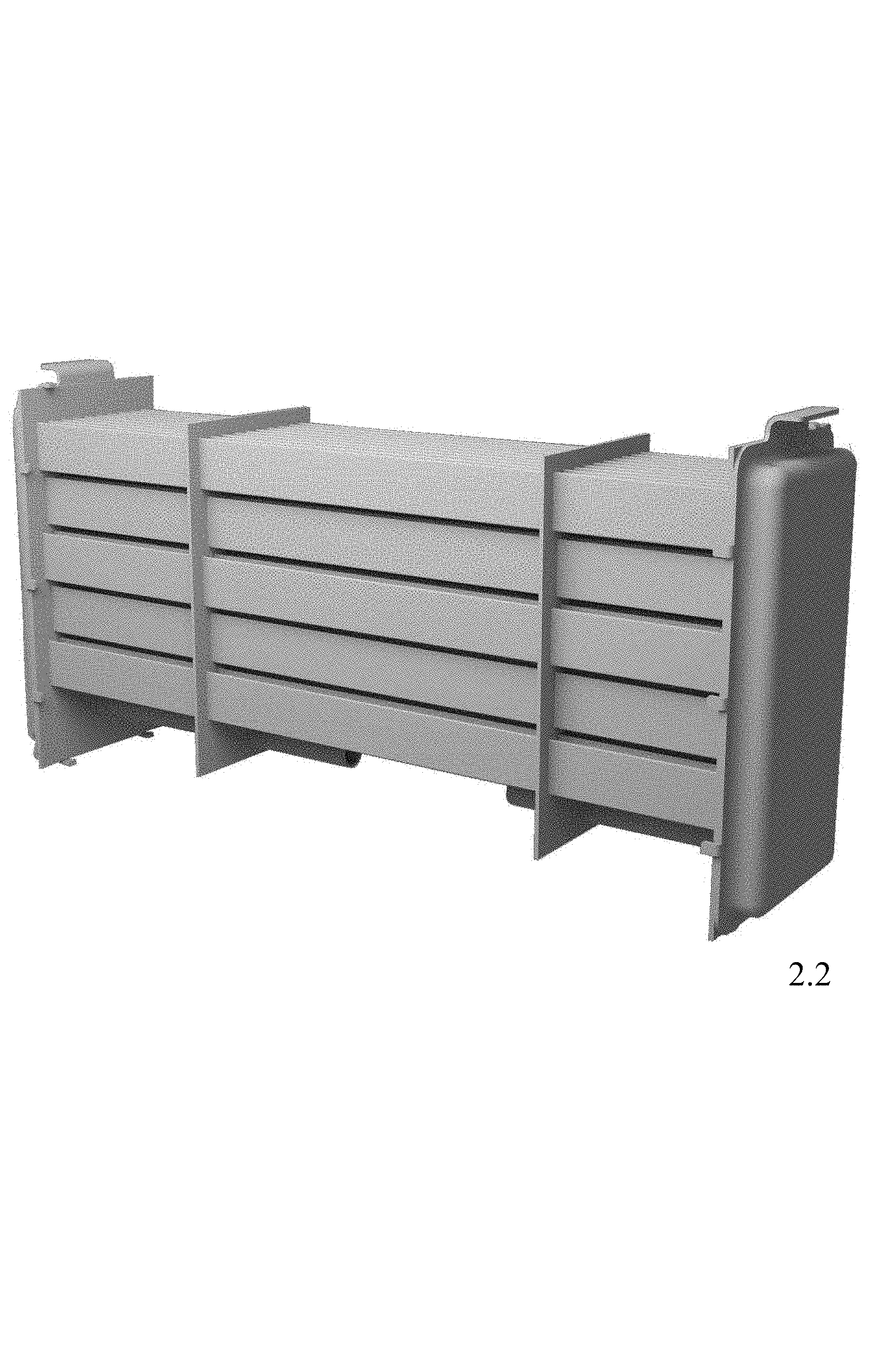
2.2 is a top, front, and right side perspective view of the heat exchanger of FIG. 2.1;
2.3 is a top, rear and left side perspective view of the heat exchanger of FIG. 2.1 with a portion removed for completeness of the disclosure;
2.4 is an enlarged and partial rear and left side perspective view of the heat exchanger of FIG. 2.1;
2.5 is a top plan view of the heat exchanger of FIGS. 2.1; and
2.6 is a left side elevational view of the heat exchanger of FIG. 2.1 with a portion removed for completeness of the disclosure;
3.1 is a bottom, front, and right side perspective view of another alternate embodiment of a heat exchanger;
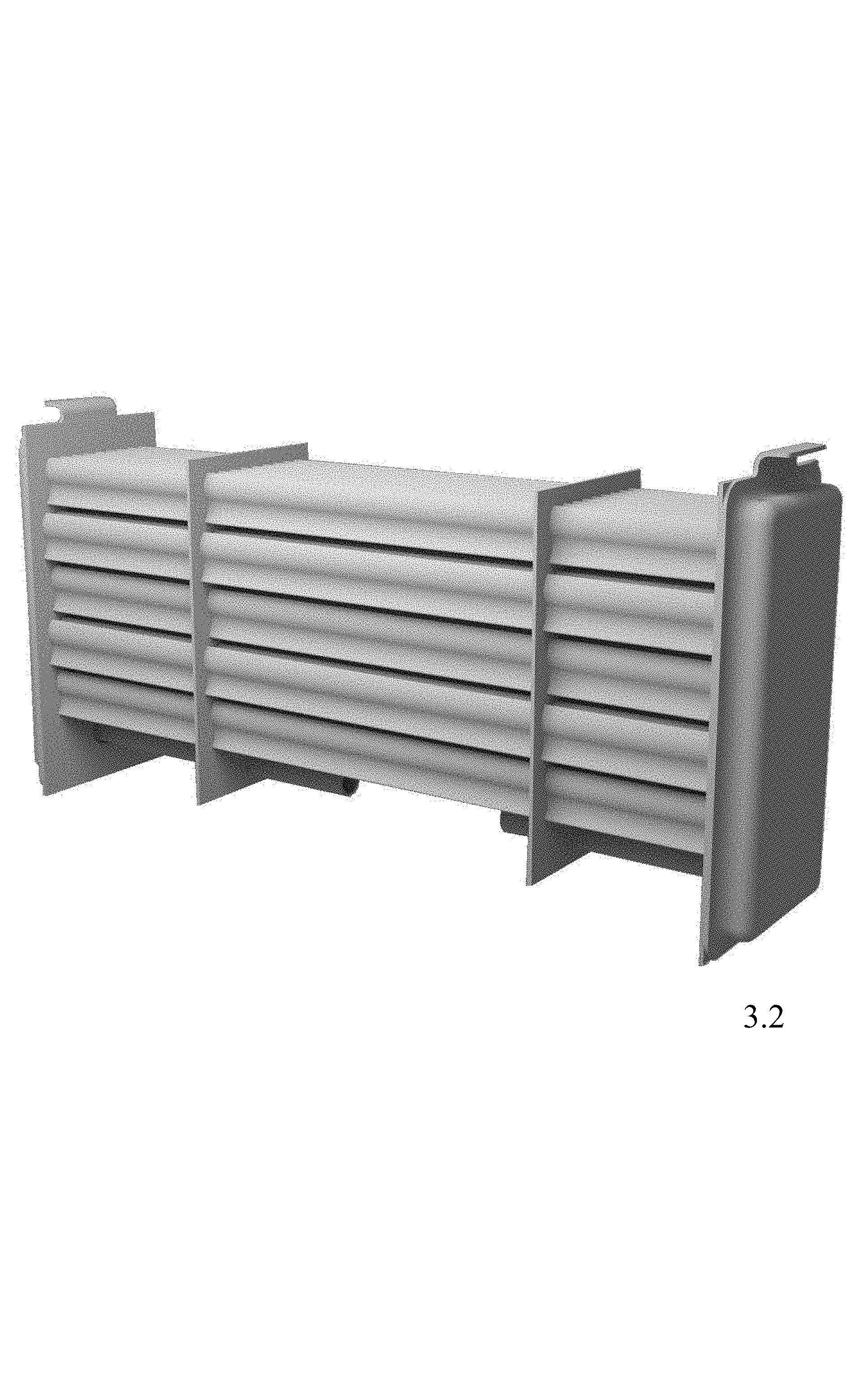
3.2 is a top, front, and right side perspective view of the heat exchanger of FIG. 3.1;
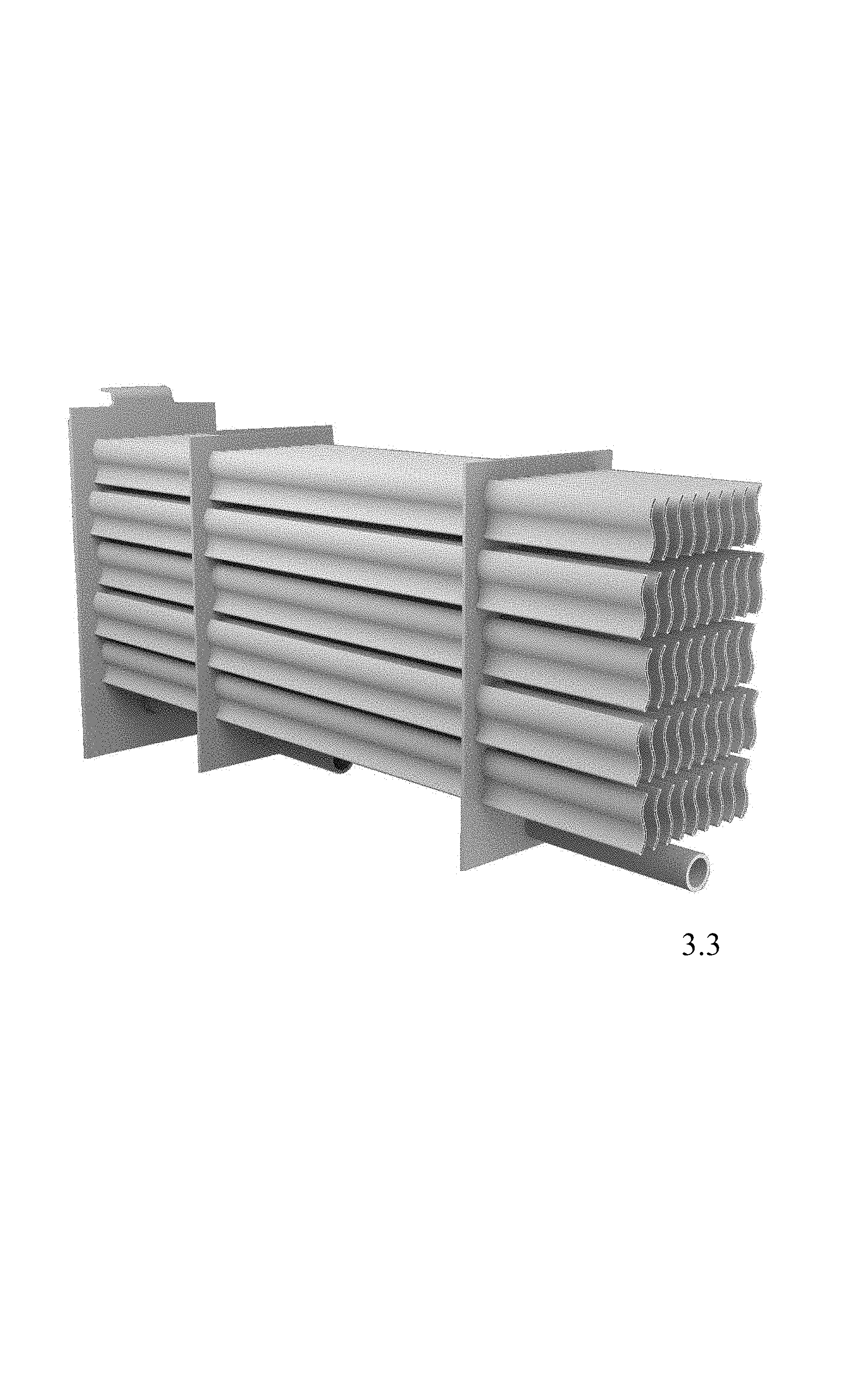
3.3 is a top, rear and left side perspective view of the heat exchanger of FIG. 3.1 with a portion removed for completeness of the disclosure;
3.4 is an enlarged and partial rear and left side perspective view of the heat exchanger of FIG. 3.1;
3.5 is a top plan view of the heat exchanger of FIG. 3.1; and
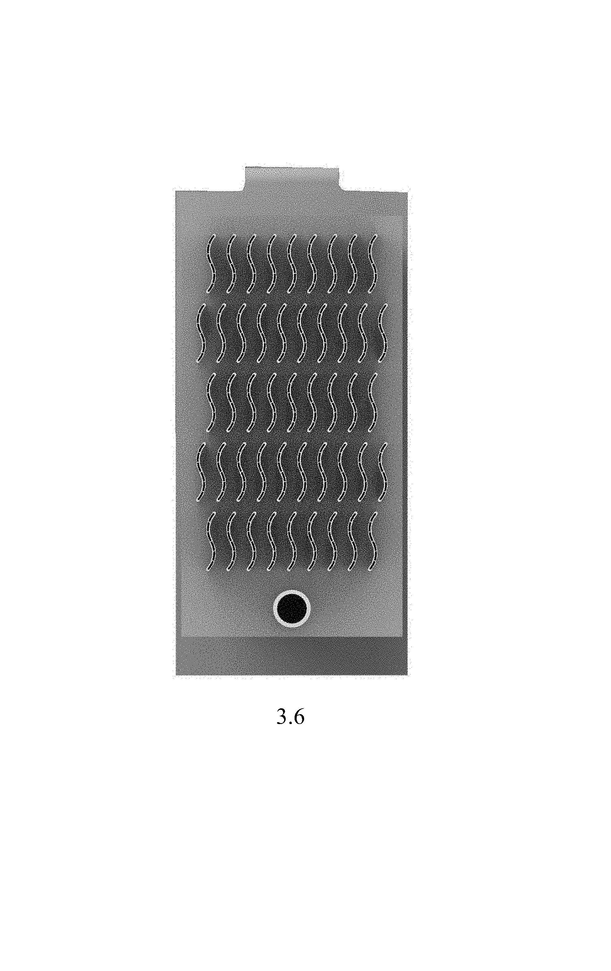
3.6 is a left side elevational view of the heat exchanger of FIG. 3.1.
* * * * *
References
D00000
D00001
D00002
D00003
D00004
D00005
D00006
D00007
D00008
D00009
D00010
D00011
D00012
D00013
D00014

D00015
XML
uspto.report is an independent third-party trademark research tool that is not affiliated, endorsed, or sponsored by the United States Patent and Trademark Office (USPTO) or any other governmental organization. The information provided by uspto.report is based on publicly available data at the time of writing and is intended for informational purposes only.
While we strive to provide accurate and up-to-date information, we do not guarantee the accuracy, completeness, reliability, or suitability of the information displayed on this site. The use of this site is at your own risk. Any reliance you place on such information is therefore strictly at your own risk.
All official trademark data, including owner information, should be verified by visiting the official USPTO website at www.uspto.gov. This site is not intended to replace professional legal advice and should not be used as a substitute for consulting with a legal professional who is knowledgeable about trademark law.