Battery end charger
Oliver , et al.
U.S. patent number D842,802 [Application Number D/617,783] was granted by the patent office on 2019-03-12 for battery end charger. This patent grant is currently assigned to Accutronics Ltd.. The grantee listed for this patent is Accutronics Ltd. Invention is credited to David Asplin, Steve Dodds, Neil Oliver.


| United States Patent | D842,802 |
| Oliver , et al. | March 12, 2019 |
Battery end charger
Claims
CLAIM An ornamental design for the battery end charger, as shown and described.
| Inventors: | Oliver; Neil (Staffordshire, GB), Asplin; David (Staffordshire, GB), Dodds; Steve (Staffordshire, GB) | ||||||||||
|---|---|---|---|---|---|---|---|---|---|---|---|
| Applicant: |
|
||||||||||
| Assignee: | Accutronics Ltd.
(GB) |
||||||||||
| Appl. No.: | D/617,783 | ||||||||||
| Filed: | September 15, 2017 |
Related U.S. Patent Documents
| Application Number | Filing Date | Patent Number | Issue Date | ||
|---|---|---|---|---|---|
| 29591226 | Apr 14, 2016 | D797660 | |||
| 29485393 | May 31, 2016 | D757645 | |||
Foreign Application Priority Data
| Sep 18, 2013 [EP] | 002311787 | |||
| Current U.S. Class: | D13/107 |
| Current International Class: | 1302 |
| Field of Search: | ;D13/107,103,106,110,184,82,120,159,168,116,119,162.1 ;429/96,97,99,100,105,163,82,120,176 ;320/103,107,110,120,125,113 |
References Cited [Referenced By]
U.S. Patent Documents
| 3105909 | October 1963 | Jones |
| D206804 | January 1967 | Cunitz |
| D210596 | March 1968 | Becker et al. |
| 3579075 | May 1971 | Floyd |
| D225013 | October 1972 | Stewart |
| 3696283 | October 1972 | Ackley, III |
| D225109 | November 1972 | Flider |
| 3711806 | January 1973 | Flentge |
| D236493 | August 1975 | Kaye |
| D246709 | December 1977 | Pomper |
| D252568 | August 1979 | Comstock |
| D260513 | September 1981 | Comstock |
| 4403182 | September 1983 | Yeh |
| D276495 | November 1984 | Sylvia |
| D278703 | May 1985 | Chiodo et al. |
| D286770 | November 1986 | Melcher |
| D305115 | December 1989 | Kondo |
| 5039929 | August 1991 | Veistroffer et al. |
| D328057 | July 1992 | Prager |
| D336631 | June 1993 | Ivester |
| 5221210 | June 1993 | Bormuth et al. |
| D338653 | August 1993 | Morgan |
| D351134 | October 1994 | Hunziker |
| D377790 | February 1997 | Ober et al. |
| D377986 | February 1997 | Pollard |
| D388764 | January 1998 | Bartling et al. |
| D409562 | May 1999 | Johansson et al. |
| D414752 | October 1999 | Rooyakkers |
| D494940 | August 2004 | Fiocchi |
| D519919 | May 2006 | Yokota |
| D555587 | November 2007 | Yamamoto et al. |
| D592134 | May 2009 | Brockington |
| D610539 | February 2010 | Dahan et al. |
| D614124 | April 2010 | Mistyurik |
| D620886 | August 2010 | Flattinger |
| D623125 | September 2010 | Kawabata et al. |
| D643811 | August 2011 | Qualls et al. |
| 8054041 | November 2011 | Kim et al. |
| D650326 | December 2011 | Yen |
| D651562 | January 2012 | Takeno |
| D651564 | January 2012 | Workman |
| D654019 | February 2012 | Ikegame |
| D659088 | May 2012 | Steinberg |
| D664499 | July 2012 | Workman |
| 8312937 | November 2012 | Turner et al. |
| D674333 | January 2013 | Lemelman et al. |
| D675622 | February 2013 | Petrick et al. |
| D680950 | April 2013 | Nam et al. |
| D693292 | November 2013 | Salvi et al. |
| D721647 | January 2015 | DeKeuster |
| D727254 | April 2015 | Kinoshita |
| D731412 | June 2015 | Gao et al. |
| D731415 | June 2015 | Arakelian et al. |
| D733043 | June 2015 | Hasbrook et al. |
| D733045 | June 2015 | Venida et al. |
| D742307 | November 2015 | DeKeuster |
| D757645 | May 2016 | Oliver |
| D758960 | June 2016 | Johansson |
| D790453 | June 2017 | Tinius |
| D797660 | September 2017 | Oliver |
| D803777 | November 2017 | Burchard |
| D820200 | June 2018 | Takahashi |
| D826150 | August 2018 | Cayon |
| D826848 | August 2018 | Toshida |
| 2001/0007728 | July 2001 | Ogata et al. |
| 2006/0093899 | May 2006 | Jeon et al. |
| 2012/0194132 | August 2012 | Ikegame |
| 2012/0214038 | August 2012 | Kim et al. |
| 2013/0183573 | July 2013 | Yoshioka |
| 2015/0214586 | July 2015 | Yeow et al. |
| 2015/0364740 | December 2015 | De Arroyabe |
| 2016/0248072 | August 2016 | Jang et al. |
| 2017/0125752 | May 2017 | Kim |
Description
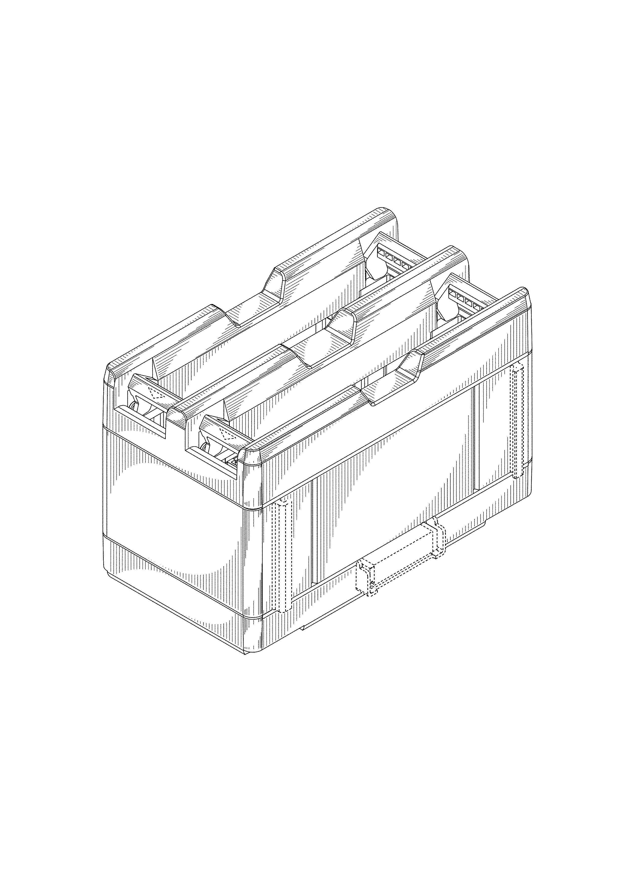
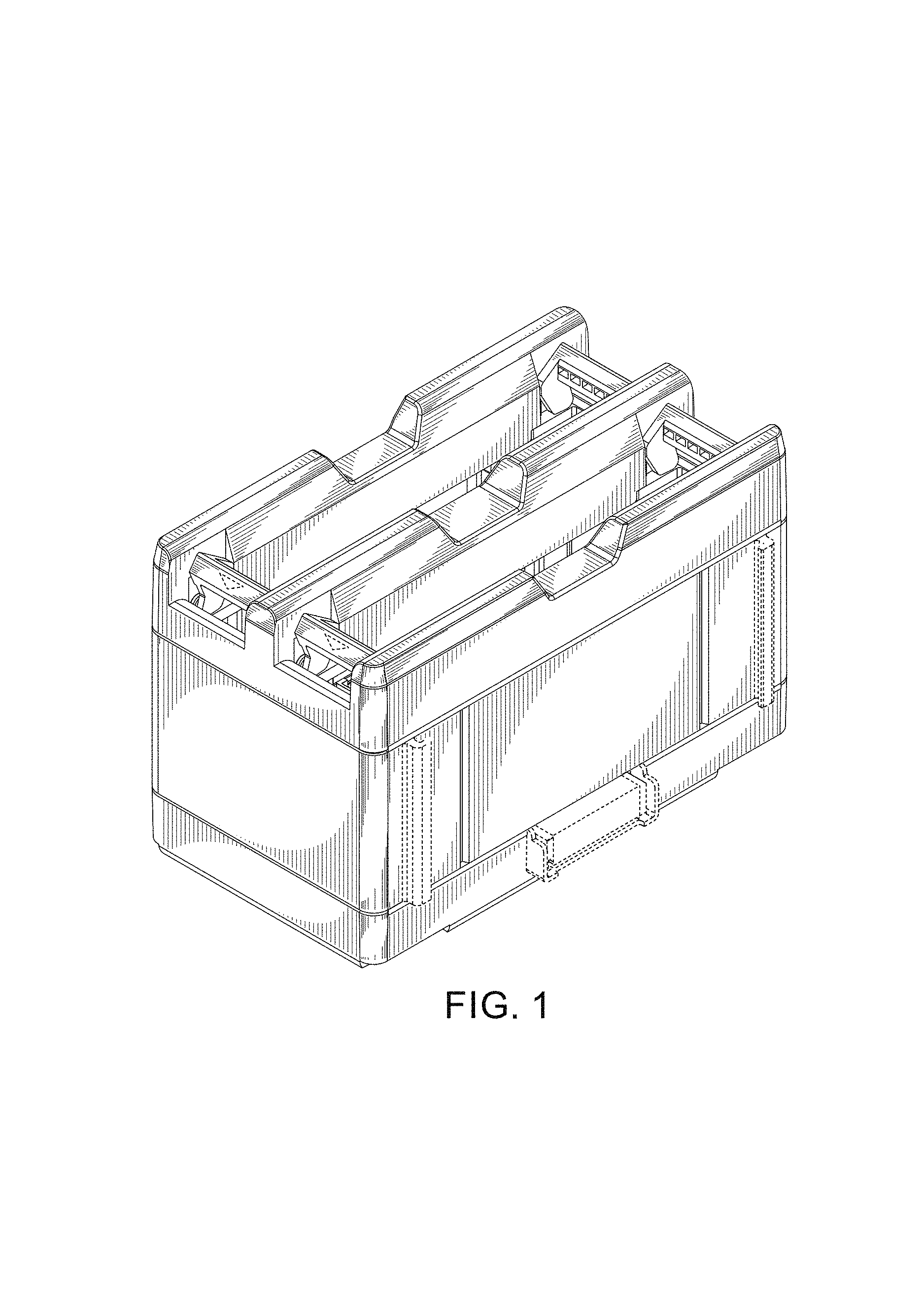
FIG. 1 is a first perspective view of an embodiment of our new battery end charger;
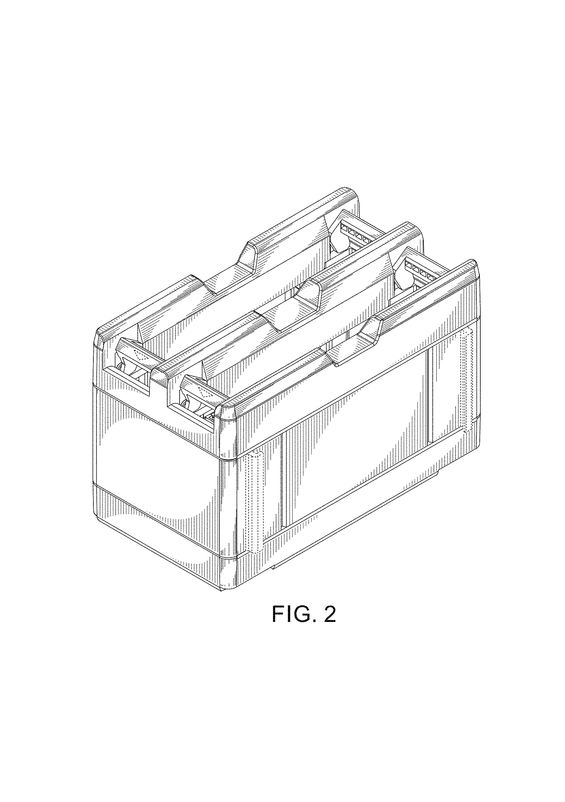
FIG. 2 is a second perspective view of the design of FIG. 1;
FIG. 3 is a front view of the design of FIG. 1;
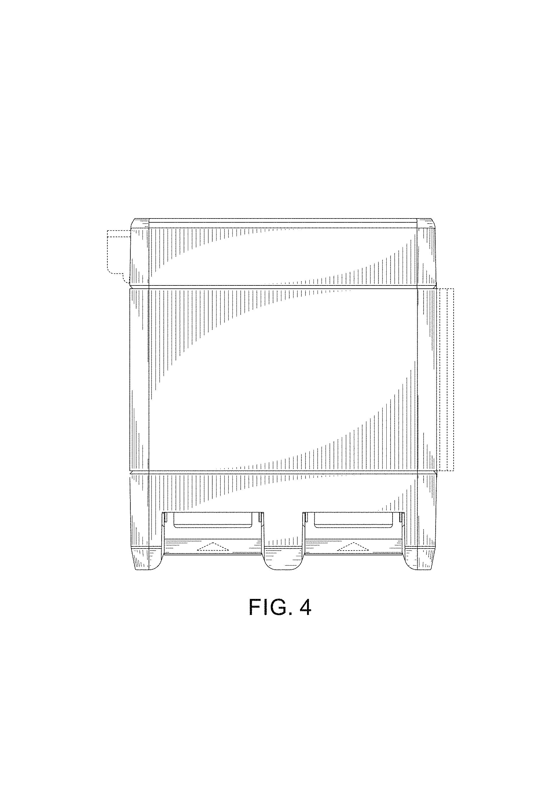
FIG. 4 is a top view of the design of FIG. 1;
FIG. 5 is a bottom view of the design of FIG. 1;
FIG. 6 is a left hand side view of the design of FIG. 1; and,
FIG. 7 is a right hand side view of the design of FIG. 1.
The broken lines in the above described FIGS. 1-7 are for illustrative purposes only and form no part of the claimed design.
* * * * *
D00000
D00001
D00002
D00003
D00004
D00005
D00006
D00007
XML
uspto.report is an independent third-party trademark research tool that is not affiliated, endorsed, or sponsored by the United States Patent and Trademark Office (USPTO) or any other governmental organization. The information provided by uspto.report is based on publicly available data at the time of writing and is intended for informational purposes only.
While we strive to provide accurate and up-to-date information, we do not guarantee the accuracy, completeness, reliability, or suitability of the information displayed on this site. The use of this site is at your own risk. Any reliance you place on such information is therefore strictly at your own risk.
All official trademark data, including owner information, should be verified by visiting the official USPTO website at www.uspto.gov. This site is not intended to replace professional legal advice and should not be used as a substitute for consulting with a legal professional who is knowledgeable about trademark law.