Utensil
Bloch , et al.
U.S. patent number D842,662 [Application Number D/621,716] was granted by the patent office on 2019-03-12 for utensil. This patent grant is currently assigned to Outdoor Edge Cutlery Corp.. The grantee listed for this patent is Outdoor Edge Cutlery Corporation. Invention is credited to David R. Bloch, HouKun Liang.


View All Diagrams
| United States Patent | D842,662 |
| Bloch , et al. | March 12, 2019 |
Utensil
Claims
CLAIM The ornamental design for a utensil, as shown and described.
| Inventors: | Bloch; David R. (Morrison, CO), Liang; HouKun (Guangdong, CN) | ||||||||||
|---|---|---|---|---|---|---|---|---|---|---|---|
| Applicant: |
|
||||||||||
| Assignee: | Outdoor Edge Cutlery Corp.
(Denver, CO) |
||||||||||
| Appl. No.: | D/621,716 | ||||||||||
| Filed: | October 11, 2017 |
| Current U.S. Class: | D7/643; D7/653; D7/642; D7/401.2 |
| Current International Class: | 0703 |
| Field of Search: | ;D7/154,368,401.2,642-645,653-664,669,675-677,683,688-689,691 ;D8/107,300-301 ;D22/117-118 |
References Cited [Referenced By]
U.S. Patent Documents
| 34712 | March 1862 | Gables |
| 972777 | October 1910 | Richardson |
| 1053387 | February 1913 | Hawley |
| 1229696 | June 1917 | Woods |
| 1337174 | April 1920 | Whyte |
| 1372325 | March 1921 | Willemin |
| 1425750 | August 1922 | Crawford |
| 2010074 | August 1935 | Fuerst |
| 2318129 | May 1943 | Torode |
| 2470492 | May 1949 | Jenkins |
| 3771224 | November 1973 | Bono, Jr. |
| D342422 | December 1993 | Sanford |
| 5845403 | December 1998 | Nivin |
| D414988 | October 1999 | Santini |
| 6105259 | August 2000 | Meyers |
| D575593 | August 2008 | Svartstrom |
| D608602 | January 2010 | Davies |
| D609060 | February 2010 | Pallotto |
| D656799 | April 2012 | Lebeau |
| D722837 | February 2015 | Miksovsky |
| D741116 | October 2015 | Mundhra |
| D746644 | January 2016 | Cai |
| D753447 | April 2016 | Busboom |
| D758808 | June 2016 | Gatewood |
| D794400 | August 2017 | Young |
| D813616 | March 2018 | Mundhra |
Attorney, Agent or Firm: Lewis Brisbois Bisgaard & Smith LLP Mueller; Craig W.
Description
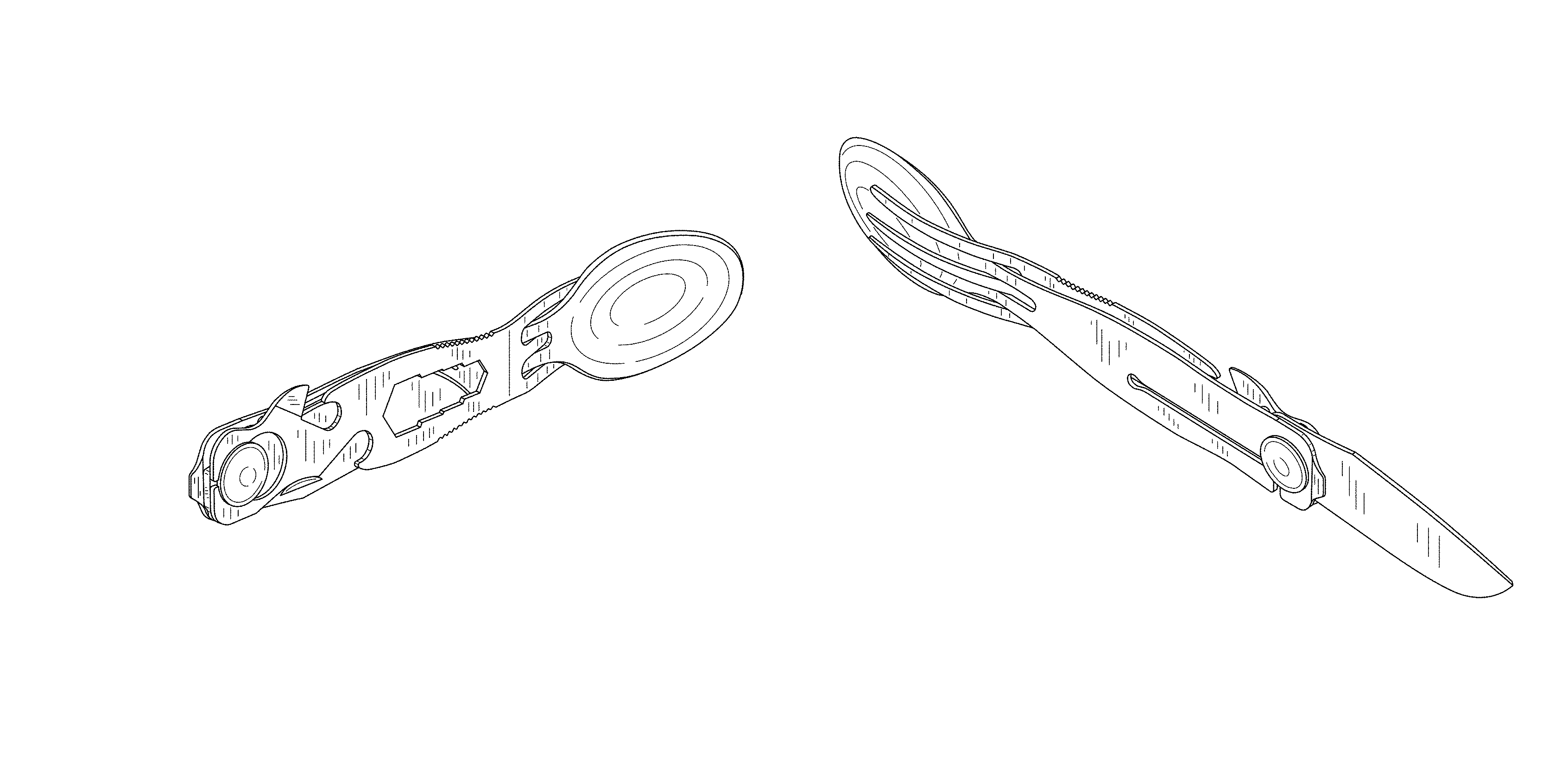
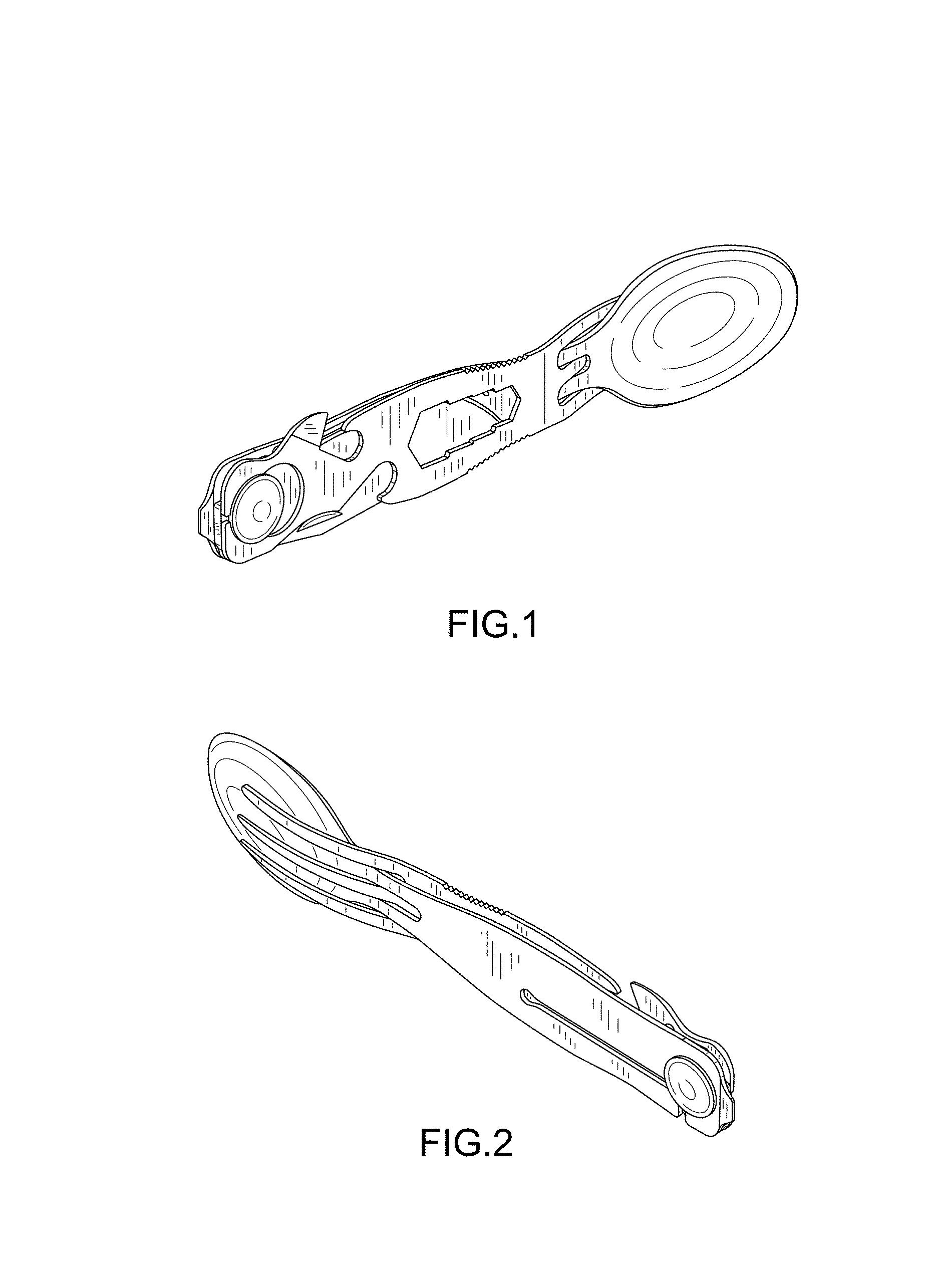
FIG. 1 is a front perspective view of the utensil showing the new design;
FIG. 2 is a rear perspective view thereof;
FIG. 3 is a front elevation view thereof;
FIG. 4 is a rear elevation view thereof;
FIG. 5 is a left elevation view thereof;
FIG. 6 is a right elevation view thereof;
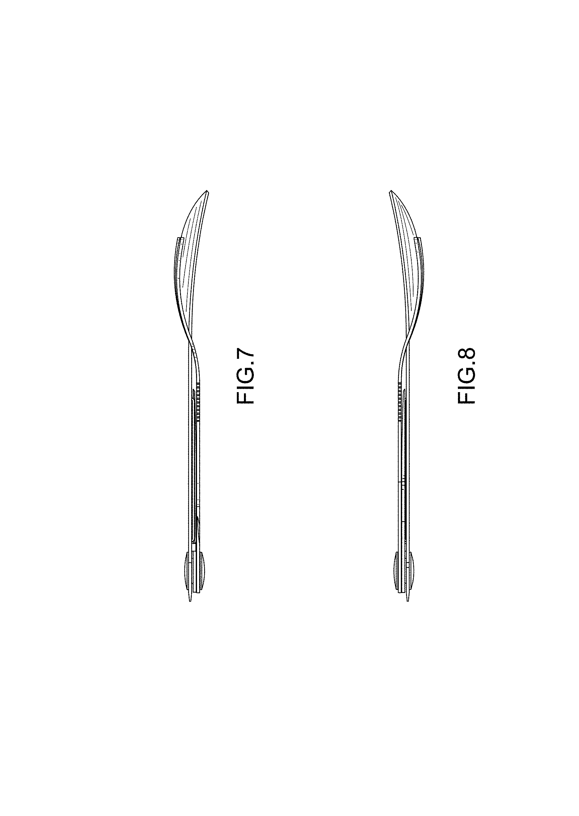
FIG. 7 is a top plan view thereof;
FIG. 8 is a bottom plan view thereof;
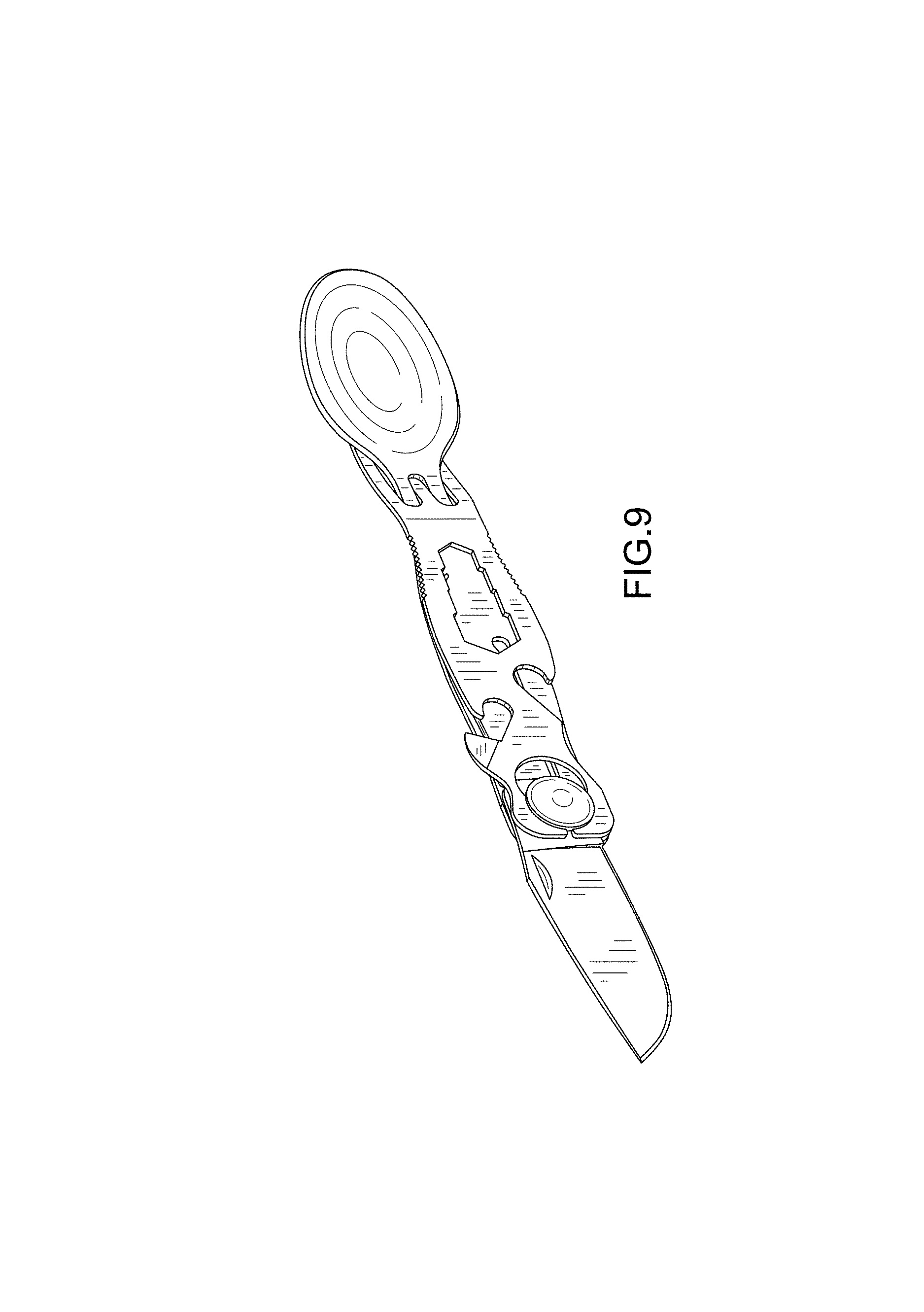
FIG. 9 is a front perspective view of the utensil of FIG. 1 in a second position of use wherein the knife is deployed;
FIG. 10 is a rear perspective view thereof;
FIG. 11 is a front elevation view thereof;
FIG. 12 is a rear elevation view thereof;
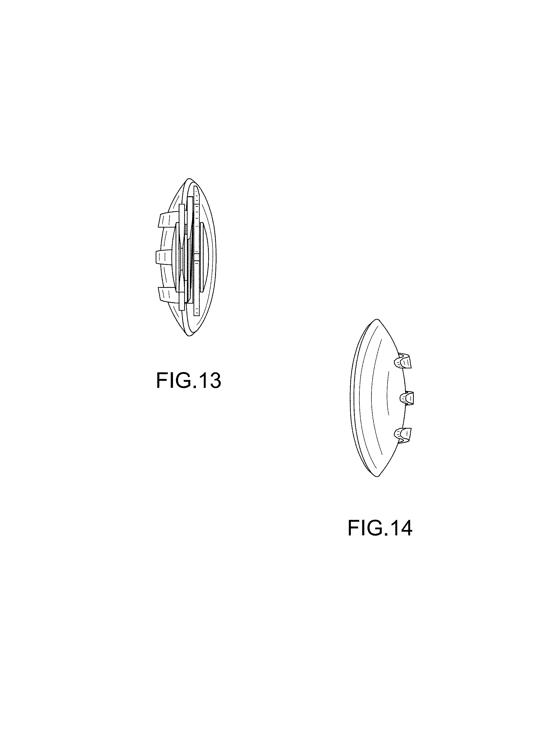
FIG. 13 is a left elevation view thereof;
FIG. 14 is a right elevation view thereof;
FIG. 15 is a top plan view thereof;
FIG. 16 is a bottom plan view thereof;
FIG. 17 is an exploded front perspective view of the utensil of FIG. 1 in a third position of use wherein the knife is deployed and the fork is removed from the spoon and knife sub-assembly;
FIG. 18 is an exploded rear perspective view thereof;
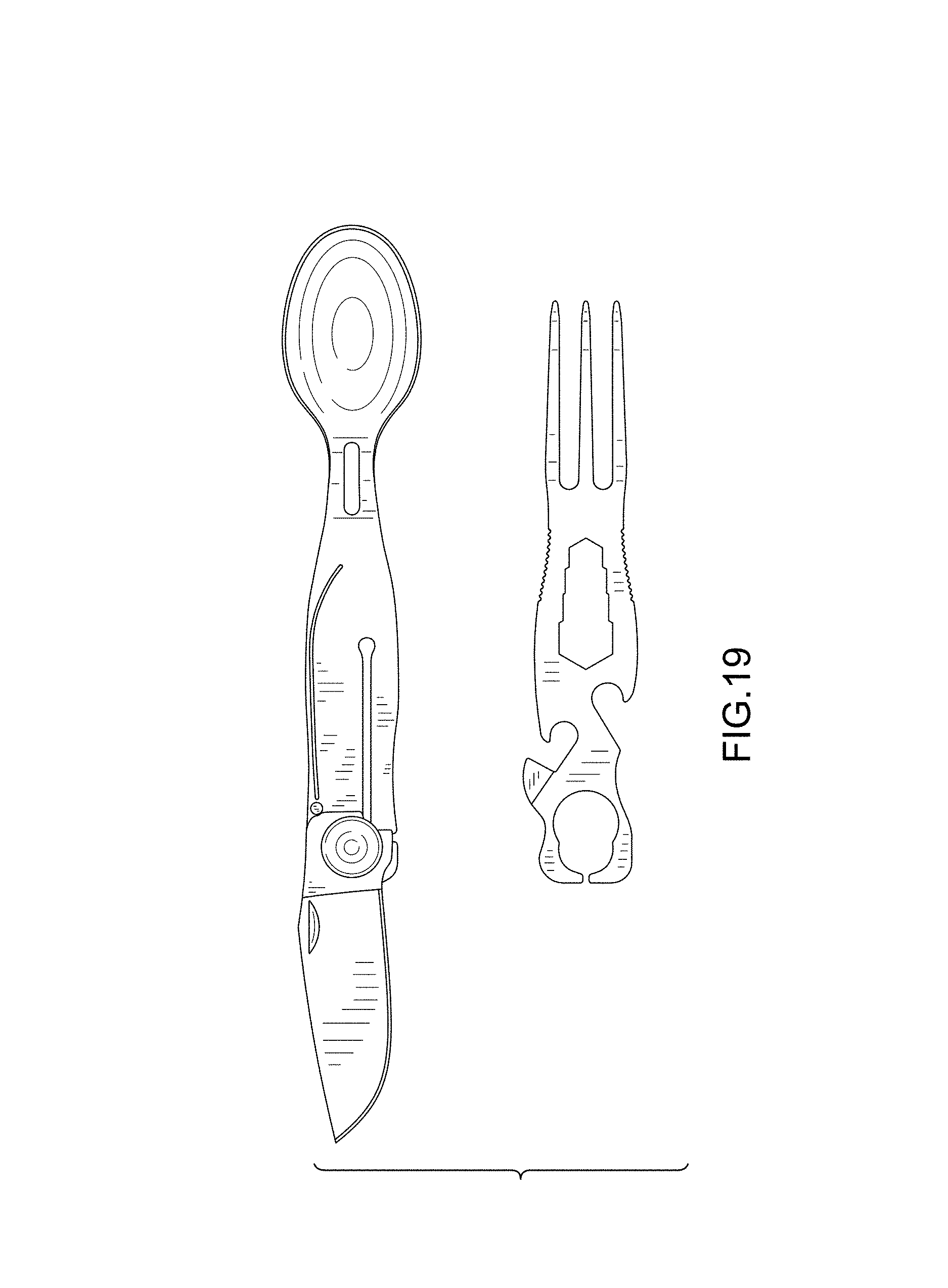
FIG. 19 is an exploded front elevation view thereof;
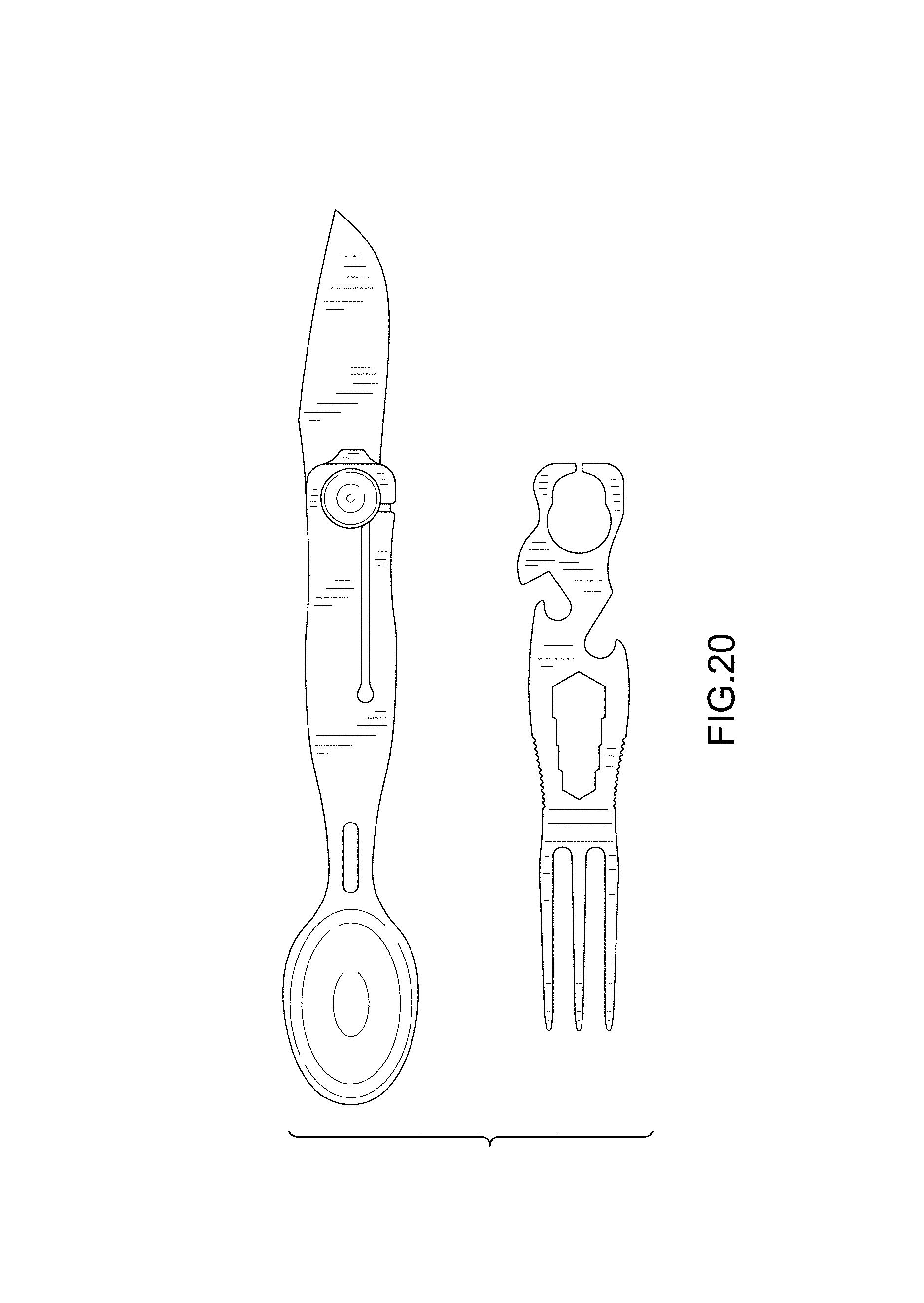
FIG. 20 is an exploded rear elevation view thereof;
FIG. 21 is an exploded left elevation view thereof;
FIG. 22 is an exploded right elevation view thereof;
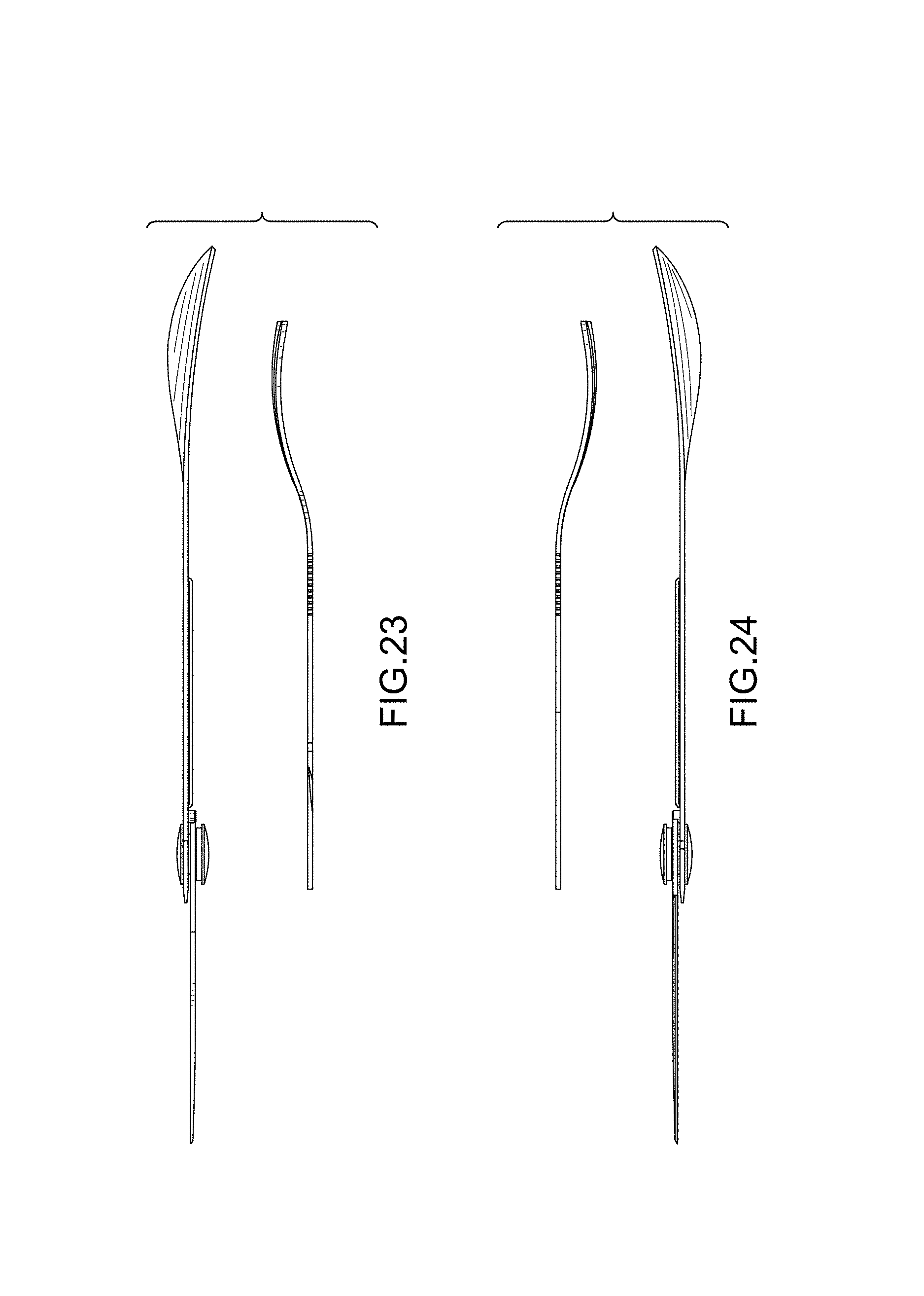
FIG. 23 is an exploded top plan view thereof; and,
FIG. 24 is an exploded bottom plan view thereof.
* * * * *
D00000
D00001
D00002
D00003
D00004
D00005
D00006
D00007
D00008
D00009
D00010
D00011
D00012
D00013
D00014

D00015

D00016
XML
uspto.report is an independent third-party trademark research tool that is not affiliated, endorsed, or sponsored by the United States Patent and Trademark Office (USPTO) or any other governmental organization. The information provided by uspto.report is based on publicly available data at the time of writing and is intended for informational purposes only.
While we strive to provide accurate and up-to-date information, we do not guarantee the accuracy, completeness, reliability, or suitability of the information displayed on this site. The use of this site is at your own risk. Any reliance you place on such information is therefore strictly at your own risk.
All official trademark data, including owner information, should be verified by visiting the official USPTO website at www.uspto.gov. This site is not intended to replace professional legal advice and should not be used as a substitute for consulting with a legal professional who is knowledgeable about trademark law.