Mobile communication device case
Robertson
U.S. patent number D842,290 [Application Number D/596,096] was granted by the patent office on 2019-03-05 for mobile communication device case. The grantee listed for this patent is Kai Robertson. Invention is credited to Kai Robertson.


View All Diagrams
| United States Patent | D842,290 |
| Robertson | March 5, 2019 |
Mobile communication device case
Claims
CLAIM The ornamental design for a mobile communication device case, as show and described.
| Inventors: | Robertson; Kai (Chicago, IL) | ||||||||||
|---|---|---|---|---|---|---|---|---|---|---|---|
| Applicant: |
|
||||||||||
| Appl. No.: | D/596,096 | ||||||||||
| Filed: | March 6, 2017 |
| Current U.S. Class: | D14/250; D14/251 |
| Current International Class: | 1403 |
| Field of Search: | ;D2/639 ;D3/201,218,232,233,239,242,245-247,269,273,301,303,318,327,328 ;D11/212,218,231,222,236,237 ;D13/103,107,108,119 ;D14/137,138R,138AA,138C,138G,203.3-203.7,217,238.1,247,248,250,251-253,439,440 ;D21/662,692 |
References Cited [Referenced By]
U.S. Patent Documents
| 823868 | June 1906 | Huntington et al. |
| 1865509 | July 1932 | Domkee |
| 2231259 | February 1941 | Elwell |
| D271413 | November 1983 | Munroe |
| D271820 | December 1983 | Allen |
| D288865 | March 1987 | Nace |
| D290349 | June 1987 | Kasai |
| D303456 | September 1989 | Selisky |
| D313122 | December 1990 | De Gray |
| D388249 | December 1997 | Negron |
| D490238 | May 2004 | Bristel |
| D590386 | April 2009 | Leith et al. |
| D597737 | August 2009 | Collins |
| D620252 | July 2010 | Keels |
| D649087 | November 2011 | Harada |
| D667172 | September 2012 | Baum et al. |
| D673162 | December 2012 | Young |
| D674380 | January 2013 | Soekoro |
| D675197 | January 2013 | Losiewicz |
| D677252 | March 2013 | Baum et al. |
| D685376 | July 2013 | Kim |
| D687026 | July 2013 | Ruvolo |
| D689477 | September 2013 | Baum et al. |
| D689479 | September 2013 | Soffer |
| D701043 | March 2014 | Minn |
| D703647 | April 2014 | Kim |
| D703658 | April 2014 | Higashi |
| D705767 | May 2014 | Yoon |
| 8746448 | June 2014 | Bellace |
| D711866 | August 2014 | Kawata |
| D716287 | October 2014 | Ambriz |
| D717780 | November 2014 | Tussy |
| D721373 | January 2015 | Logereau |
| D721691 | January 2015 | Kim |
| 8950638 | February 2015 | Wangerey, Jr. et al. |
| D724310 | March 2015 | Dong |
| D725659 | March 2015 | Tussy |
| D729787 | May 2015 | Soekoro |
| D729790 | May 2015 | Baum et al. |
| D735695 | August 2015 | Murphy |
| D738872 | September 2015 | Erickson-Davis |
| D743409 | November 2015 | Chen |
| 9179565 | November 2015 | Cho |
| 9185197 | November 2015 | Keesling et al. |
| D749069 | February 2016 | Senoff |
| D749083 | February 2016 | Senoff |
| D749559 | February 2016 | Senoff |
| D753912 | April 2016 | Spero |
| D765662 | September 2016 | Kang |
| D769854 | October 2016 | Duval |
| D775619 | January 2017 | Tien |
| 2009/0090750 | April 2009 | Alcenat |
| 2011/0034221 | February 2011 | Hung et al. |
| 2013/0277992 | October 2013 | Senoff |
| 2014/0151417 | June 2014 | Gayler |
| 2014/0252786 | September 2014 | Singhal |
| 2015/0327642 | November 2015 | Lee, Sr. |
Other References
|
MingShore silicone rugged case, posted at Dhgate.com, posting date Jan. 5, 2017, [online], [site visited Feb. 13, 2018]. Available from Internet, <URL: https://www.dhgate.com/product/mingshore-portable-exquisite-hand- -band-design/397517196.html>. cited by examiner . UMX Fashion buckle series, posted at Umei.com, posting date Oct. 10, 1999, [online], [site visited Feb. 13, 2018]. Available from Internet, <URL: https://www.umei.com/adjusters/buckle-adjusters-4.htm>. cited by examiner . Claro 2 Gang Decorator Wallplate by Lutron, posted at Homedepot.com, posting date Jul. 26, 2012, [online], [site visited Feb. 13, 2018]. Available from Internet, <URL: https://www.homedepot.com/p/Lutron-Claro-2-Gang-Decorator-Wallplate-Biscu- it-SC-2-BI/202102217>. cited by examiner . Daypack by Topo Designs, posted at Topodesigns.com, posting date Sep. 22, 2014, [online], [site visited Feb. 13, 2018]. Available from Internet, <URL: https://topodesigns.com/products/daypack>. cited by examiner. |
Primary Examiner: Krakower; Susan E
Assistant Examiner: Grabenstetter; L. A.
Attorney, Agent or Firm: Cooley LLP Poulsen; Nathan W.
Description
FIG. 1 is a front perspective view of a first embodiment of the new design for a mobile communication device case, with a strap in a collapsed configuration;
FIG. 2 is a rear perspective view thereof;
FIG. 3 is a front view thereof;
FIG. 4 is a rear view thereof;
FIG. 5 is a left side view thereof;
FIG. 6 is a right side view thereof;
FIG. 7 is a top view thereof;
FIG. 8 is a bottom view thereof;
FIG. 9 is a front perspective view of the first embodiment of the new design for a mobile communication device case, with the strap in an extended configuration;
FIG. 10 is a rear perspective view thereof;
FIG. 11 is a front view thereof;
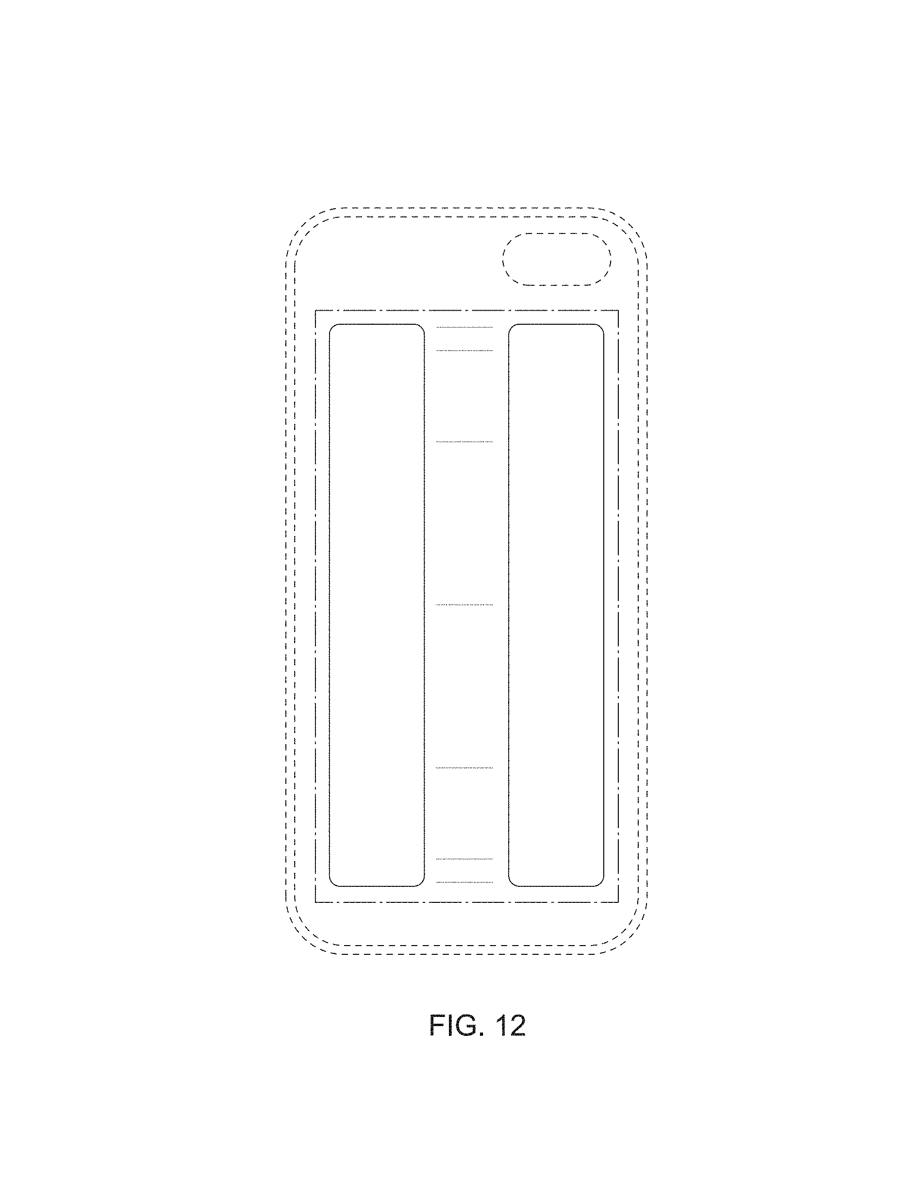
FIG. 12 is a rear view thereof;
FIG. 13 is a left side view thereof;
FIG. 14 is a right side view thereof;
FIG. 15 is a top view thereof;
FIG. 16 is a bottom view thereof;
FIG. 17 is a front perspective view thereof, showing an example use;
FIG. 18 is a front view of a second embodiment of the new design for a mobile communication device case, with a strap in a collapsed configuration;
FIG. 19 is a rear view thereof;
FIG. 20 is a left side view thereof;
FIG. 21 is a right side view thereof;
FIG. 22 is a top view thereof;
FIG. 23 is a bottom view thereof;
FIG. 24 is a front view of the second embodiment of the new design for a mobile communication device case, with the strap in an extended configuration;
FIG. 25 is a rear view thereof;
FIG. 26 is a left side view thereof;
FIG. 27 is a right side view thereof;
FIG. 28 is a top view thereof;
FIG. 29 is a bottom view thereof;
FIG. 30 is a front view of a third embodiment of the new design for a mobile communication device case, with a strap in a collapsed configuration;
FIG. 31 is a rear view thereof;
FIG. 32 is a left side view thereof;
FIG. 33 is a right side view thereof;
FIG. 34 is a top view thereof;
FIG. 35 is a bottom view thereof;
FIG. 36 is a front view of the third embodiment of the new design for a mobile communication device case, with the strap in an extended configuration;
FIG. 37 is a rear view thereof;
FIG. 38 is a left side view thereof;
FIG. 39 is a right side view thereof;
FIG. 40 is a top view thereof;
FIG. 41 is a bottom view thereof;
FIG. 42 is a front view of a fourth embodiment of the new design for a mobile communication device case, with a strap in a collapsed configuration;
FIG. 43 is a rear view thereof;
FIG. 44 is a left side view thereof;
FIG. 45 is a right side view thereof;
FIG. 46 is a top view thereof;
FIG. 47 is a bottom view thereof;
FIG. 48 is a front perspective view of the fourth embodiment of the new design for a mobile communication device case, with the strap in an extended configuration;
FIG. 49 is a front view thereof;
FIG. 50 is a rear view thereof;
FIG. 51 is a left side view thereof;
FIG. 52 is a right side view thereof;
FIG. 53 is a top view thereof;
FIG. 54 is a bottom view thereof;
FIG. 55 is a front view of a fifth embodiment of the new design for a mobile communication device case, with a strap in a collapsed configuration;
FIG. 56 is a rear view thereof;
FIG. 57 is a left side view thereof;
FIG. 58 is a right side view thereof;
FIG. 59 is a top view thereof;
FIG. 60 is a bottom view thereof;
FIG. 61 is a front view of the fifth embodiment of the new design for a mobile communication device case, with the strap in an extended configuration;
FIG. 62 is a rear view thereof;
FIG. 63 is a left side view thereof;
FIG. 64 is a right side view thereof;
FIG. 65 is a top view thereof;
FIG. 66 is a bottom view thereof;
FIG. 67 is a front view of a sixth embodiment of the new design for a mobile communication device case, with a strap in a collapsed configuration;
FIG. 68 is a rear view thereof;
FIG. 69 is a left side view thereof;
FIG. 70 is a right side view thereof;
FIG. 71 is a top view thereof;
FIG. 72 is a bottom view thereof;
FIG. 73 is a front view of the sixth embodiment of the new design for a mobile communication device case, with the strap in an extended configuration;
FIG. 74 is a rear view thereof;
FIG. 75 is a left side view thereof;
FIG. 76 is a right side view thereof;
FIG. 77 is a top view thereof; and,
FIG. 78 is a bottom view thereof.
The dash-dot-dash broken lines represent the boundary of the claim, and form no part of the claimed design. The dash-dash broken lines show portions of the case which form no part of the claimed design. The dash-dot-dot-dash broken lines depicting a hand in FIG. 17 represent environmental subject matter that forms no part of the claimed design.
* * * * *
References
D00000
D00001
D00002
D00003
D00004
D00005
D00006
D00007
D00008
D00009
D00010
D00011
D00012

D00013

D00014

D00015

D00016

D00017

D00018

D00019

D00020

D00021

D00022

D00023

D00024

D00025

D00026

D00027

D00028

D00029

D00030

D00031

D00032

D00033

D00034

D00035

D00036

D00037

D00038

D00039

D00040

D00041

D00042

D00043

D00044

D00045

D00046

D00047

D00048

D00049

D00050

D00051

D00052

D00053

D00054

XML
uspto.report is an independent third-party trademark research tool that is not affiliated, endorsed, or sponsored by the United States Patent and Trademark Office (USPTO) or any other governmental organization. The information provided by uspto.report is based on publicly available data at the time of writing and is intended for informational purposes only.
While we strive to provide accurate and up-to-date information, we do not guarantee the accuracy, completeness, reliability, or suitability of the information displayed on this site. The use of this site is at your own risk. Any reliance you place on such information is therefore strictly at your own risk.
All official trademark data, including owner information, should be verified by visiting the official USPTO website at www.uspto.gov. This site is not intended to replace professional legal advice and should not be used as a substitute for consulting with a legal professional who is knowledgeable about trademark law.