Overflow cap
Whitehead Ja
U.S. patent number D839,397 [Application Number D/596,009] was granted by the patent office on 2019-01-29 for overflow cap. This patent grant is currently assigned to IPS CORPORATION. The grantee listed for this patent is IPS Corporation. Invention is credited to James H. Whitehead.


View All Diagrams
| United States Patent | D839,397 |
| Whitehead | January 29, 2019 |
Overflow cap
Claims
CLAIM The ornamental design for an overflow cap, shown and described.
| Inventors: | Whitehead; James H. (Collierville, TN) | ||||||||||
|---|---|---|---|---|---|---|---|---|---|---|---|
| Applicant: |
|
||||||||||
| Assignee: | IPS CORPORATION (Collierville,
TN) |
||||||||||
| Appl. No.: | D/596,009 | ||||||||||
| Filed: | March 3, 2017 |
Related U.S. Patent Documents
| Application Number | Filing Date | Patent Number | Issue Date | ||
|---|---|---|---|---|---|
| 15179355 | Jun 10, 2016 | ||||
| Current U.S. Class: | D23/260 |
| Current International Class: | 2301 |
| Field of Search: | ;D23/259-261,267-268,388,397,400,406 ;404/2-4 ;210/163-164,166 ;454/275-277,284,289,291 ;4/613,287,679,680-684,689-694,671-673 ;D9/454 |
References Cited [Referenced By]
U.S. Patent Documents
| 1375222 | April 1921 | Lutz |
| 3495280 | February 1970 | Galbiati |
| D254928 | May 1980 | Mathis |
| 4720877 | January 1988 | Watts |
| D305455 | January 1990 | Stairs, Jr. |
| D317817 | June 1991 | Stairs, Jr. |
| 5179740 | January 1993 | Marsilio et al. |
| 6073278 | June 2000 | Ball |
| 6138298 | October 2000 | Ball |
| 6216288 | April 2001 | Bernau |
| 6681420 | January 2004 | Ball |
| D501244 | January 2005 | Bantz |
| D673656 | January 2013 | Feliciano |
| D682995 | May 2013 | Feliciano |
| D682996 | May 2013 | Feliciano |
| D683436 | May 2013 | Feliciano |
| 8621683 | January 2014 | Coronado et al. |
| 8671473 | March 2014 | Morrone |
| 2004/0034926 | February 2004 | Ball |
| 2006/0085907 | April 2006 | Ball |
| 2008/0196161 | August 2008 | Ball |
| 2017/0356174 | December 2017 | Humber |
| 1 246 302 | Dec 1988 | CA | |||
| 1 253 654 | May 1989 | CA | |||
| 2012 41358 | May 2009 | CN | |||
| 2 054 145 | Nov 1970 | DE | |||
| 0 691 438 | Jan 1996 | EP | |||
| 1 826 323 | Aug 2007 | EP | |||
| 2 558 187 | Jul 1985 | FR | |||
| 2 739 115 | Mar 1997 | FR | |||
| 2 799 777 | Apr 2001 | FR | |||
| 1 216 208 | Dec 1970 | GB | |||
| 2006-063515 | Mar 2006 | JP | |||
| 2012-241488 | Dec 2012 | JP | |||
| 241770 | Jul 1995 | NZ | |||
Other References
|
WatcoFlex.RTM. (Specifications) WATCO Manufacturing Company (Mar. 2009) 2 pages. cited by applicant. |
Primary Examiner: Goodman; Eric L
Assistant Examiner: Wierenga; Amy C
Attorney, Agent or Firm: Womble Bond Dickinson (US) LLP
Description
FIG. 1 is a perspective view of a first embodiment of an overflow cap according to my new design;
FIG. 2 is another perspective view thereof;
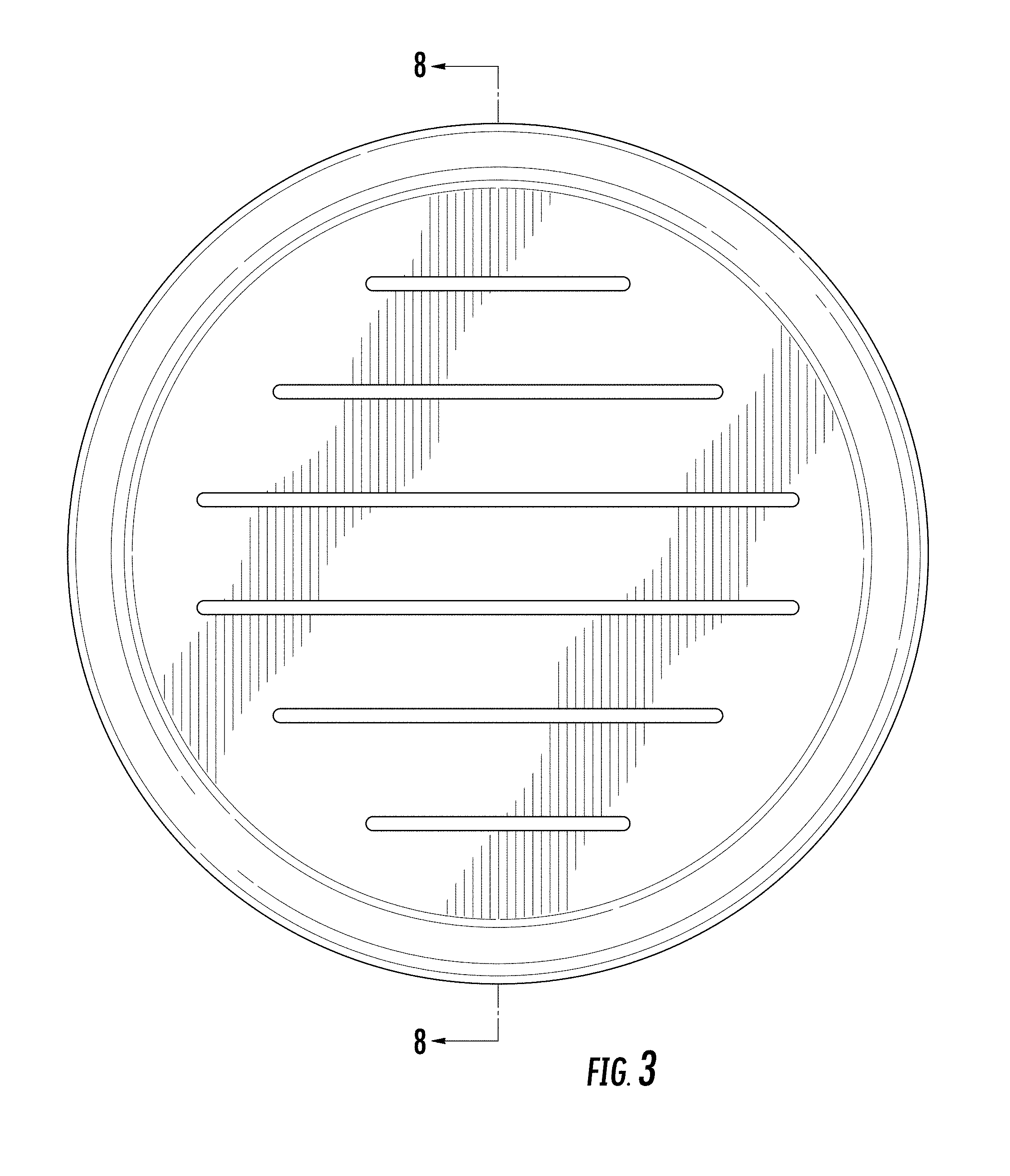
FIG. 3 is a front elevation view thereof;
FIG. 4 is a rear elevation view thereof;
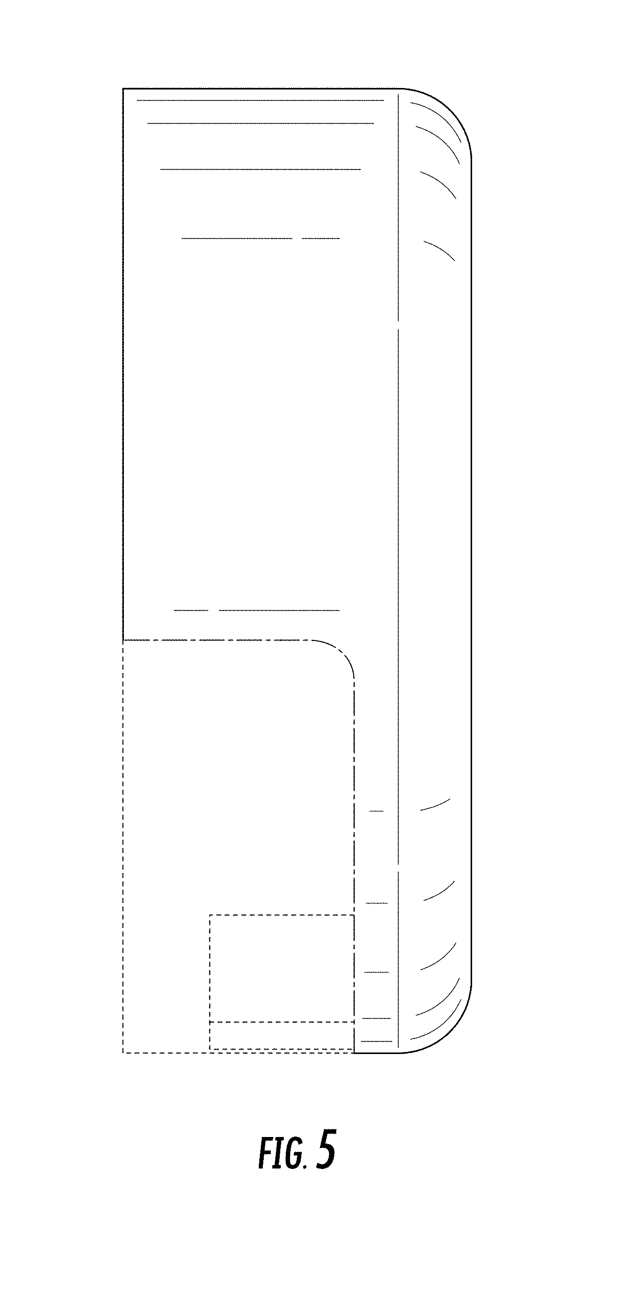
FIG. 5 is a left side elevation view thereof, the opposite, right side being a mirror image thereof;
FIG. 6 is a top plan view thereof;
FIG. 7 is a bottom plan view thereof;
FIG. 8 is a cross-sectional view thereof taken along cut lines 8-8 in FIG. 3;
FIG. 9 is a perspective view of a second embodiment of an overflow cap according to my new design;
FIG. 10 is another perspective view thereof;
FIG. 11 is a front elevation view thereof;
FIG. 12 is a rear elevation view thereof;
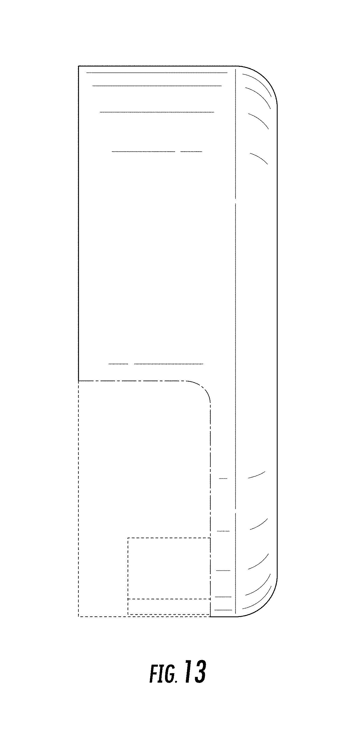
FIG. 13 is a left side elevation view thereof, the opposite, right side being a mirror image thereof;
FIG. 14 is a top plan view thereof;
FIG. 15 is a bottom plan view thereof;
FIG. 16 is a cross-sectional view thereof taken along cut lines 16-16 in FIG. 11;
FIG. 17 is a perspective view of a third embodiment of an overflow cap according to my new design;
FIG. 18 is another perspective view thereof;
FIG. 19 is a front elevation view thereof;
FIG. 20 is a rear elevation view thereof;
FIG. 21 is a left side elevation view thereof, the opposite, right side being a mirror image thereof;
FIG. 22 is a top plan view thereof;
FIG. 23 is a bottom plan view thereof; and,
FIG. 24 is a cross-sectional view thereof taken along cut lines 24-24 in FIG. 19.
The broken lines showing in the views illustrate portions of the overflow cap that form no part of the claimed design. Any shading and cross-hatching are not features of the design but are utilized to illustrate the surface contours of the design.
The dash-dot-dash broken lines illustrate boundaries and form no part of the claim.
* * * * *
D00000
D00001
D00002
D00003
D00004
D00005
D00006
D00007
D00008
D00009
D00010
D00011
D00012
D00013

D00014

D00015

D00016

D00017

D00018

D00019

D00020

D00021

XML
uspto.report is an independent third-party trademark research tool that is not affiliated, endorsed, or sponsored by the United States Patent and Trademark Office (USPTO) or any other governmental organization. The information provided by uspto.report is based on publicly available data at the time of writing and is intended for informational purposes only.
While we strive to provide accurate and up-to-date information, we do not guarantee the accuracy, completeness, reliability, or suitability of the information displayed on this site. The use of this site is at your own risk. Any reliance you place on such information is therefore strictly at your own risk.
All official trademark data, including owner information, should be verified by visiting the official USPTO website at www.uspto.gov. This site is not intended to replace professional legal advice and should not be used as a substitute for consulting with a legal professional who is knowledgeable about trademark law.