Monitoring camera
Novak , et al. Ja
U.S. patent number D839,337 [Application Number D/632,158] was granted by the patent office on 2019-01-29 for monitoring camera. This patent grant is currently assigned to AXIS AB. The grantee listed for this patent is Axis AB. Invention is credited to Daniel Ahman, Erika Backe, Morten Bergstrom, Stefan Larsson, Sara Novak, Mathias Walter.


| United States Patent | D839,337 |
| Novak , et al. | January 29, 2019 |
Monitoring camera
Claims
CLAIM We claim the ornamental design for a monitoring camera, as shown and described.
| Inventors: | Novak; Sara (Malmo, SE), Backe; Erika (Malmo, SE), Bergstrom; Morten (Lund, SE), Ahman; Daniel (Lomma, SE), Walter; Mathias (Arlov, SE), Larsson; Stefan (Lund, SE) | ||||||||||
|---|---|---|---|---|---|---|---|---|---|---|---|
| Applicant: |
|
||||||||||
| Assignee: | AXIS AB (Lund,
SE) |
||||||||||
| Appl. No.: | D/632,158 | ||||||||||
| Filed: | January 5, 2018 |
Related U.S. Patent Documents
| Application Number | Filing Date | Patent Number | Issue Date | ||
|---|---|---|---|---|---|
| 29577710 | Sep 15, 2016 | D820896 | |||
Foreign Application Priority Data
| Mar 15, 2016 [EM] | 003029412 | |||
| Current U.S. Class: | D16/203 |
| Current International Class: | 1601 |
| Field of Search: | ;D16/200-220,239,242,243,244,245 ;D3/267,265 ;D26/140,26,138,142,60,61,62,63,106,107,128,131 ;D12/187 ;D14/204,195,181,183,215,209,210,224 |
References Cited [Referenced By]
U.S. Patent Documents
| D54432 | February 1920 | MacLewee |
| D232656 | September 1974 | Aulenti |
| D253853 | January 1980 | Gerber |
| D293478 | December 1987 | Palone |
| D293720 | January 1988 | Witte |
| D360965 | August 1995 | Cullen |
| 6135615 | October 2000 | Lee |
| D481406 | October 2003 | Alessio |
| D541456 | April 2007 | Kosche |
| D574532 | August 2008 | Lee |
| D589995 | April 2009 | Kellar |
| D602623 | October 2009 | Kay |
| D635172 | March 2011 | Ko |
| D637640 | May 2011 | Park |
| D691187 | October 2013 | Seo et al. |
| D696329 | December 2013 | Horiki et al. |
| D697245 | January 2014 | Thomas et al. |
| D702274 | April 2014 | Qian |
| D721756 | January 2015 | Hallstrom et al. |
| D723603 | March 2015 | Hess, Jr. |
| D731574 | June 2015 | Hallstrom et al. |
| D753328 | April 2016 | Mathews |
| D753751 | April 2016 | Moller-Lewin et al. |
| D781361 | March 2017 | Dimitriadis et al. |
| 9593829 | March 2017 | Dupre |
| D787581 | May 2017 | Moller-Lewin et al. |
| D812279 | March 2018 | Price |
| 9940802 | April 2018 | Rosenkvist |
| D820896 | June 2018 | Novak |
| D821624 | June 2018 | Huyghe |
| D821625 | June 2018 | Couvreur |
| 2008/0226282 | September 2008 | Takahashi |
| 2009/0309968 | December 2009 | Cheng |
| 304006132 | Jan 2017 | CN | |||
| D173898 | Feb 2016 | TW | |||
Other References
|
Backe, Erica et al., "Mechanical Design of Retail Cameras", Master Thesis, Division of Machine Design, Department of Design Science, Faculty of Engineering LTH, Lund University, 2013, AXIS Communications, pp. 1-129. cited by applicant. |
Primary Examiner: Fox; Barbara
Assistant Examiner: Ramirez; Mary C
Attorney, Agent or Firm: Volpe and Koenig, P.C.
Description
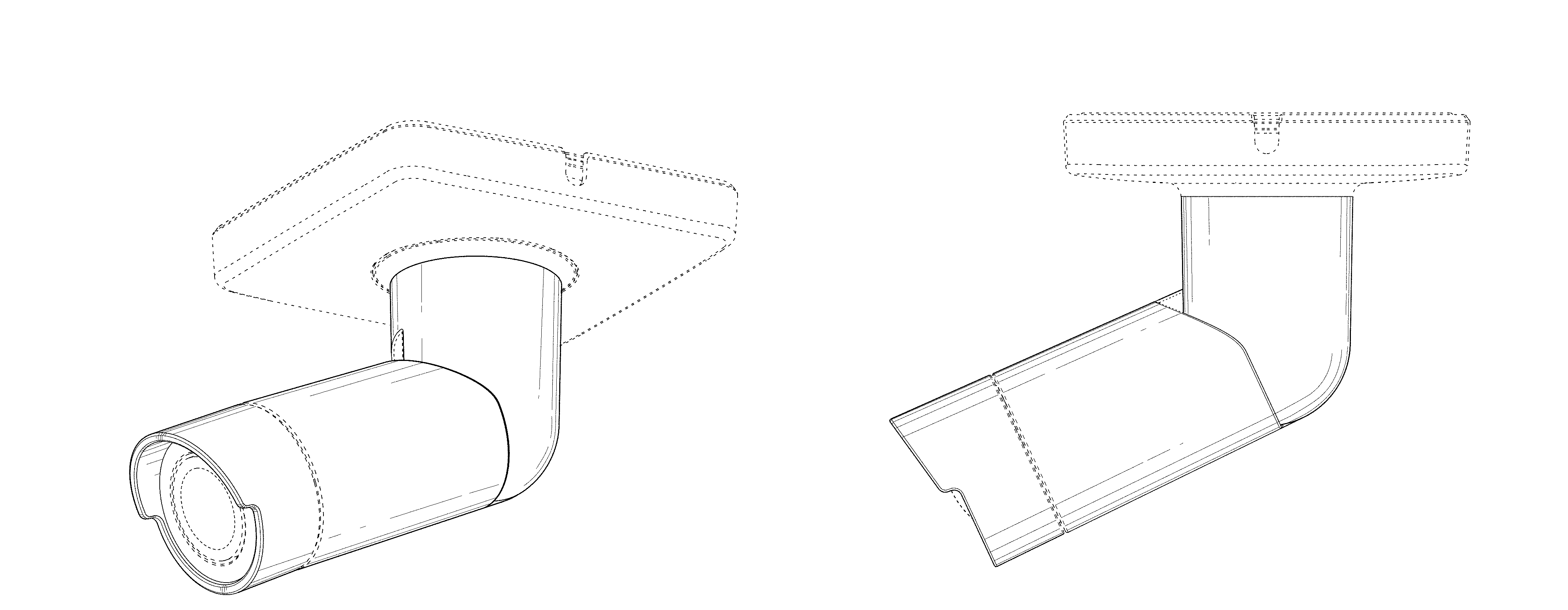
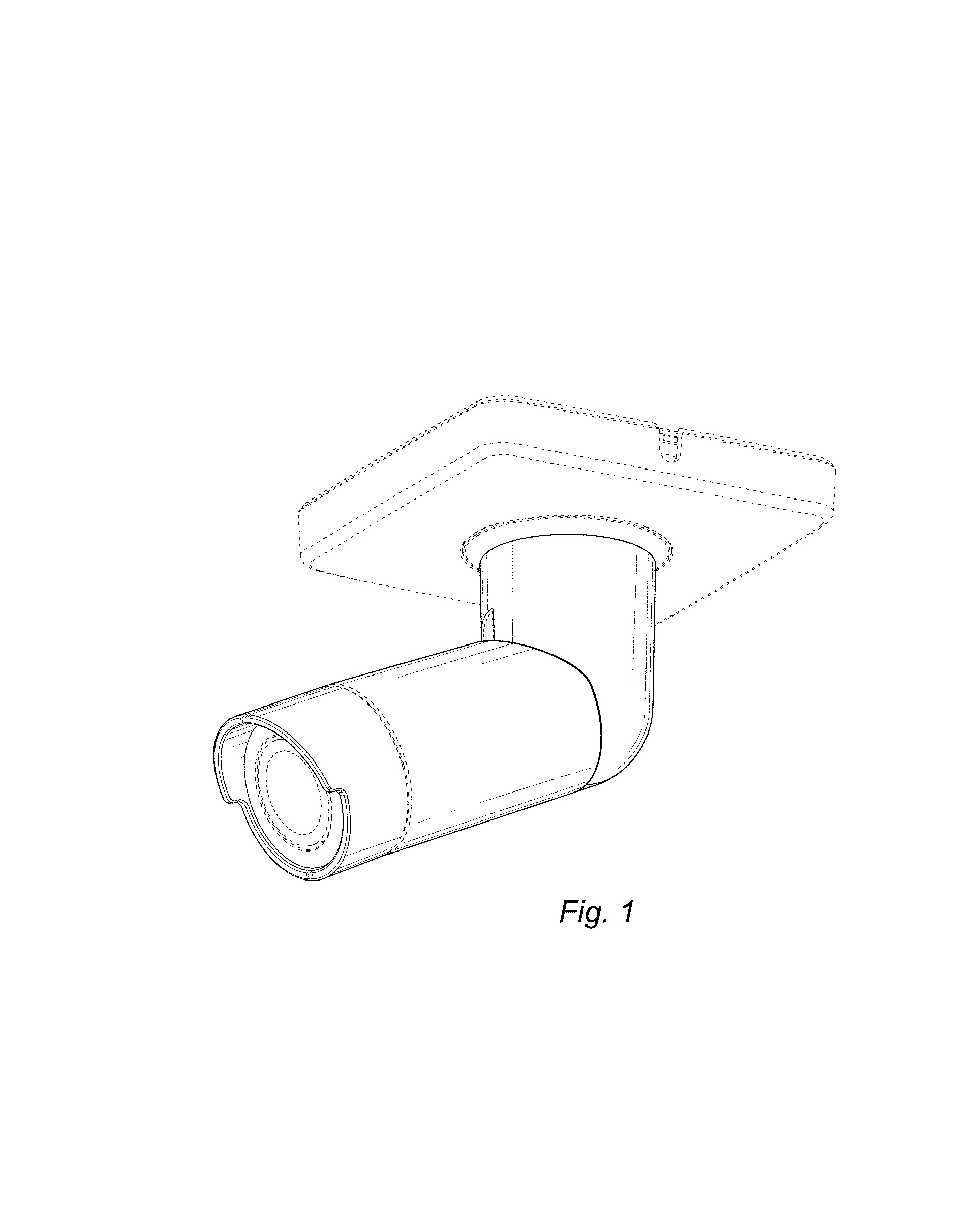
FIG. 1 is a bottom, front, right perspective view of a monitoring camera in accordance with our design;
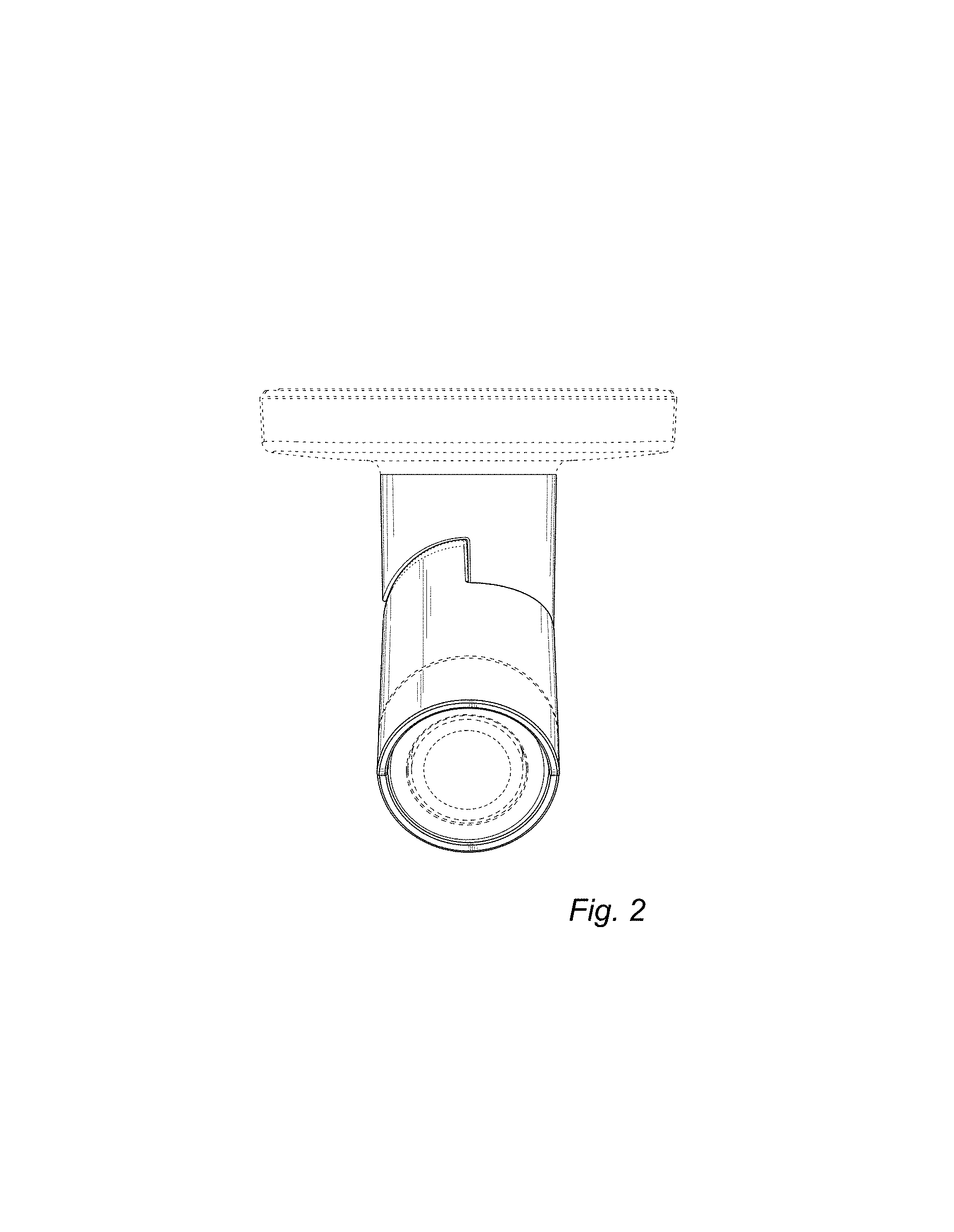
FIG. 2 is a front elevational view thereof;
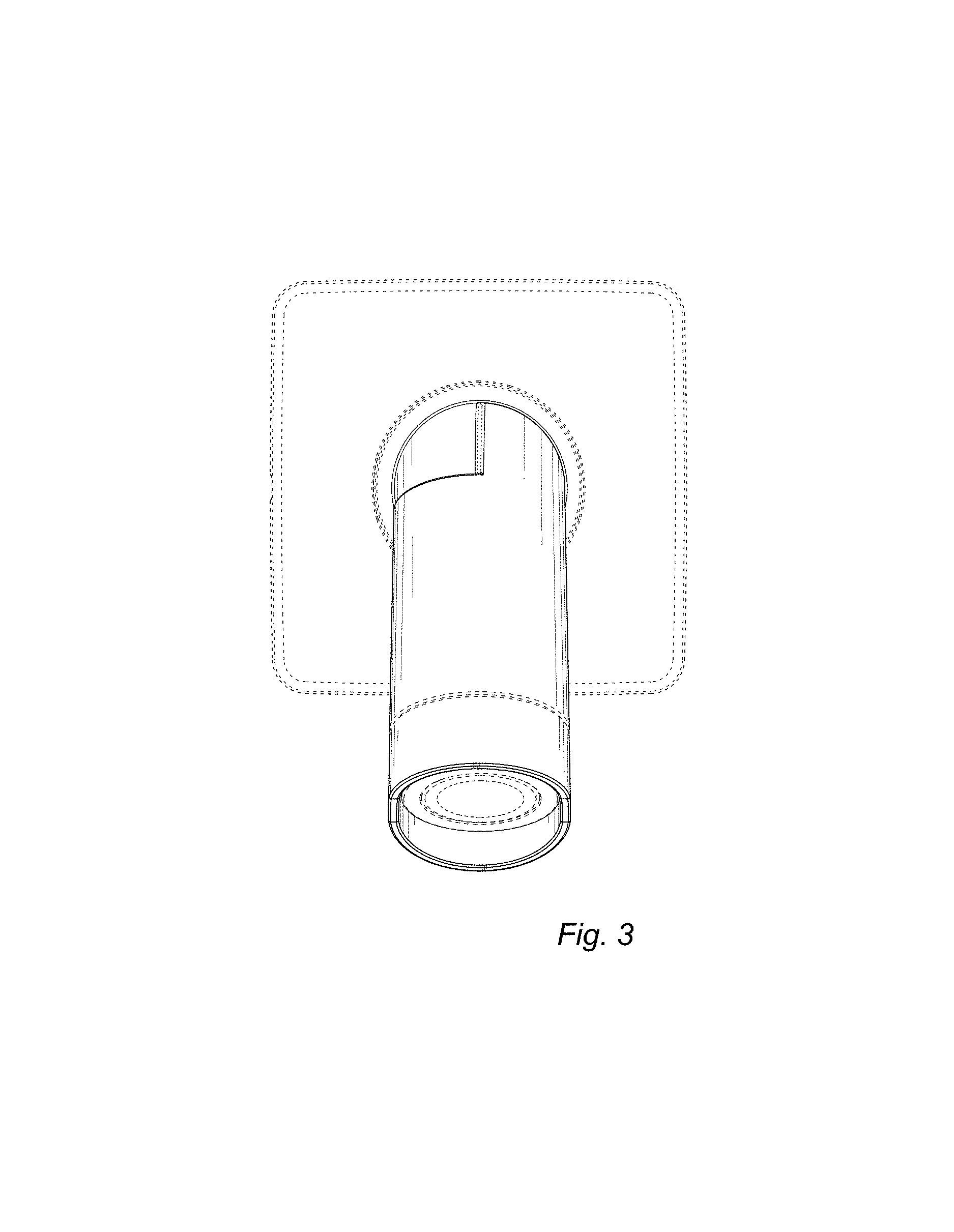
FIG. 3 is a bottom plan view thereof;
FIG. 4 is a left side elevational view thereof;
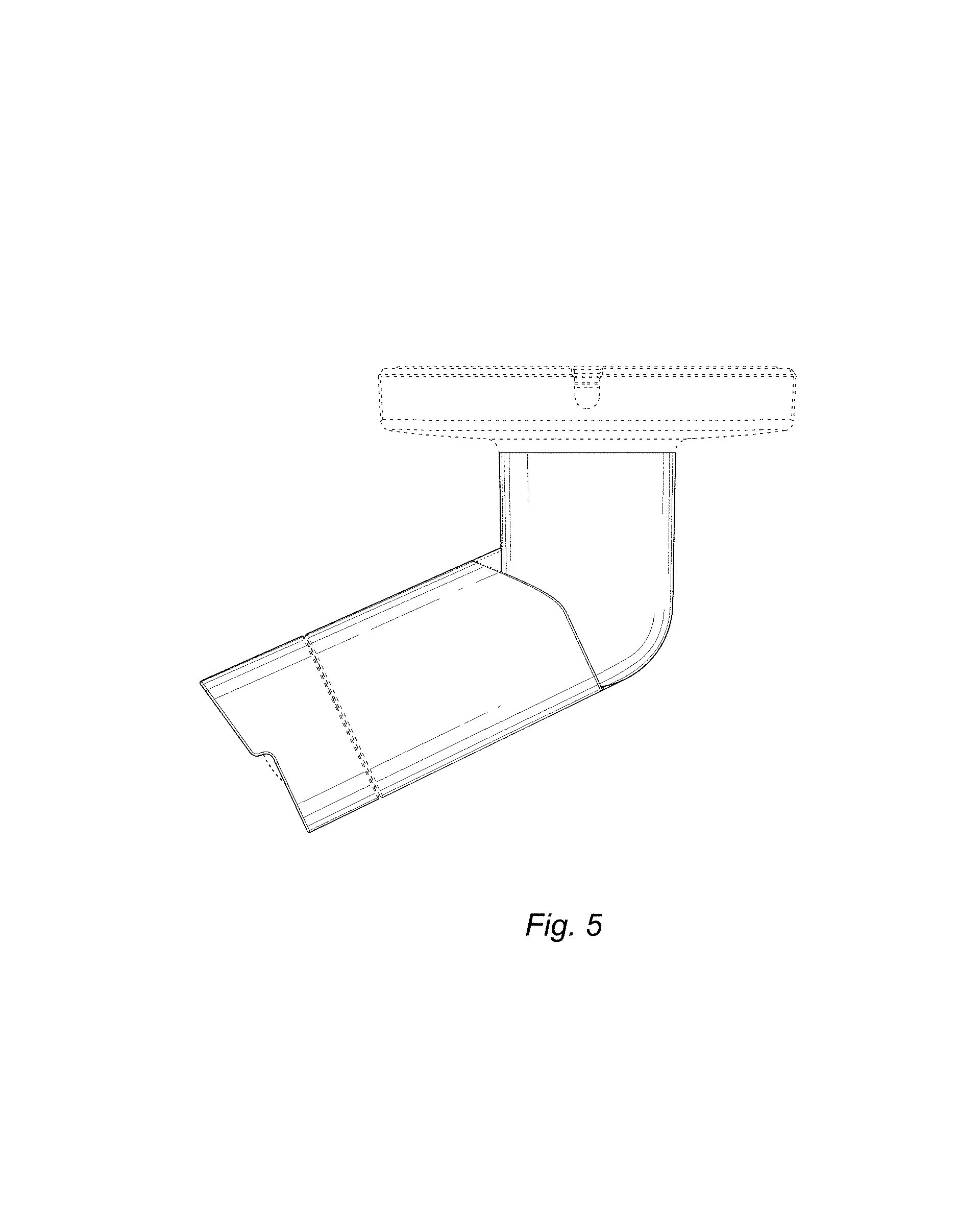
FIG. 5 is a right side elevational view thereof;
FIG. 6 is a rear elevational view thereof; and,
FIG. 7 is a top plan view thereof.
The broken lines shown in the drawings depict portions of the monitoring camera that form no part of the claimed design.
* * * * *
D00000
D00001
D00002
D00003
D00004
D00005
D00006
D00007
XML
uspto.report is an independent third-party trademark research tool that is not affiliated, endorsed, or sponsored by the United States Patent and Trademark Office (USPTO) or any other governmental organization. The information provided by uspto.report is based on publicly available data at the time of writing and is intended for informational purposes only.
While we strive to provide accurate and up-to-date information, we do not guarantee the accuracy, completeness, reliability, or suitability of the information displayed on this site. The use of this site is at your own risk. Any reliance you place on such information is therefore strictly at your own risk.
All official trademark data, including owner information, should be verified by visiting the official USPTO website at www.uspto.gov. This site is not intended to replace professional legal advice and should not be used as a substitute for consulting with a legal professional who is knowledgeable about trademark law.