Cap
Wood , et al. Ja
U.S. patent number D838,171 [Application Number D/632,034] was granted by the patent office on 2019-01-15 for cap. This patent grant is currently assigned to NOVEMBAL USA INC.. The grantee listed for this patent is NOVEMBAL USA INC.. Invention is credited to Michel Luzzato, Christopher Wood.


View All Diagrams
| United States Patent | D838,171 |
| Wood , et al. | January 15, 2019 |
Cap
Claims
CLAIM The ornamental design for a cap, as shown and described.
| Inventors: | Wood; Christopher (Wauwatosa, WI), Luzzato; Michel (Ecully, FR) | ||||||||||
|---|---|---|---|---|---|---|---|---|---|---|---|
| Applicant: |
|
||||||||||
| Assignee: | NOVEMBAL USA INC. (Edison,
NJ) |
||||||||||
| Appl. No.: | D/632,034 | ||||||||||
| Filed: | January 4, 2018 |
| Current U.S. Class: | D9/453 |
| Current International Class: | 0907 |
| Field of Search: | ;D9/428,429,432,434,435,436,439,440,443,444,445,447,449-455,499,500,503,504,705 ;D7/317,387,391,392,392.1,393,396.1,396.2,509-511,538,900 ;D3/202,203.2,294,302,318 ;D28/91 |
References Cited [Referenced By]
U.S. Patent Documents
| 4059198 | November 1977 | Mumford |
| 4595110 | June 1986 | Herr |
| D318804 | August 1991 | Ochs |
| D358769 | May 1995 | Luch |
| D407978 | April 1999 | Petro |
| D458138 | June 2002 | Fuchs |
| 6405886 | June 2002 | Gearhart et al. |
| D460357 | July 2002 | Kras |
| D465731 | November 2002 | Brant et al. |
| D481314 | October 2003 | Noonan |
| D513181 | December 2005 | Bloom |
| 6981602 | January 2006 | Ma et al. |
| D516911 | March 2006 | Bloom |
| D518717 | April 2006 | German |
| D518718 | April 2006 | von Spreckelsen |
| D518719 | April 2006 | von Spreckelsen |
| D527631 | September 2006 | Mallet |
| D534802 | January 2007 | German |
| D584149 | January 2009 | Lohrman et al. |
| D592954 | May 2009 | Capretta |
| D606864 | December 2009 | Robinson |
| D619003 | July 2010 | Benoit-Gonin |
| D632958 | February 2011 | Fuchs |
| D633386 | March 2011 | Taber |
| D634199 | March 2011 | Taber |
| D634200 | March 2011 | Taber |
| D671834 | December 2012 | Chasteen et al. |
| D673852 | January 2013 | Wood |
| D687299 | August 2013 | Peykoff et al. |
| D693221 | November 2013 | Ramsey et al. |
| D693683 | November 2013 | Ramsey et al. |
| D693685 | November 2013 | Ramsey et al. |
| 8672158 | March 2014 | Taber et al. |
| D723919 | March 2015 | Taber et al. |
| D762115 | July 2016 | Corvaglia et al. |
| D786966 | May 2017 | Matsushita et al. |
| D789201 | June 2017 | Yu |
| D790966 | July 2017 | Roberts et al. |
| D792219 | July 2017 | Bueno Nunez |
| D824257 | July 2018 | Wood |
| 2009/0014404 | January 2009 | Russell |
| 2010/0200532 | August 2010 | Ekkert |
| 2011/0290754 | December 2011 | Taber et al. |
| 2011/0290755 | December 2011 | Taber et al. |
| 2012/0031871 | February 2012 | Molinaro |
| 2013/0313218 | November 2013 | Cox et al. |
| 2014/0158660 | June 2014 | Wood |
| 2015/0122769 | May 2015 | Taber et al. |
| 2016/0332783 | November 2016 | Kim |
| 2 831 909 | Nov 2012 | CA | |||
| 2 839 370 | Dec 2012 | CA | |||
| 003750033-0001 | Feb 2017 | EM | |||
| 003750033-0002 | Feb 2017 | EM | |||
| 003750033-0003 | Feb 2017 | EM | |||
| 003750033-0004 | Feb 2017 | EM | |||
| 003750033-0005 | Feb 2017 | EM | |||
| 003750033-0006 | Feb 2017 | EM | |||
| 003750033-0007 | Feb 2017 | EM | |||
| 003750033-0008 | Feb 2017 | EM | |||
| 003750033-0009 | Feb 2017 | EM | |||
| 003995596-0001 | May 2017 | EM | |||
| 004089217-0002 | Jul 2017 | EM | |||
| 2 863 589 | Jun 2005 | FR | |||
| 2 911 584 | Jul 2008 | FR | |||
| 3318752 | Aug 2002 | JP | |||
| WO 2007/147206 | Dec 2007 | WO | |||
| WO 2011/098739 | Aug 2011 | WO | |||
| WO 2012/102599 | Aug 2012 | WO | |||
| WO 2012/102599 | Aug 2012 | WO | |||
Assistant Examiner: Arminio; Wendy L
Attorney, Agent or Firm: Finnegan, Henderson, Farabow, Garrett & Dunner LLP
Description
FIG. 1 is a top, front perspective view of a cap showing our new design in a first configuration during use;
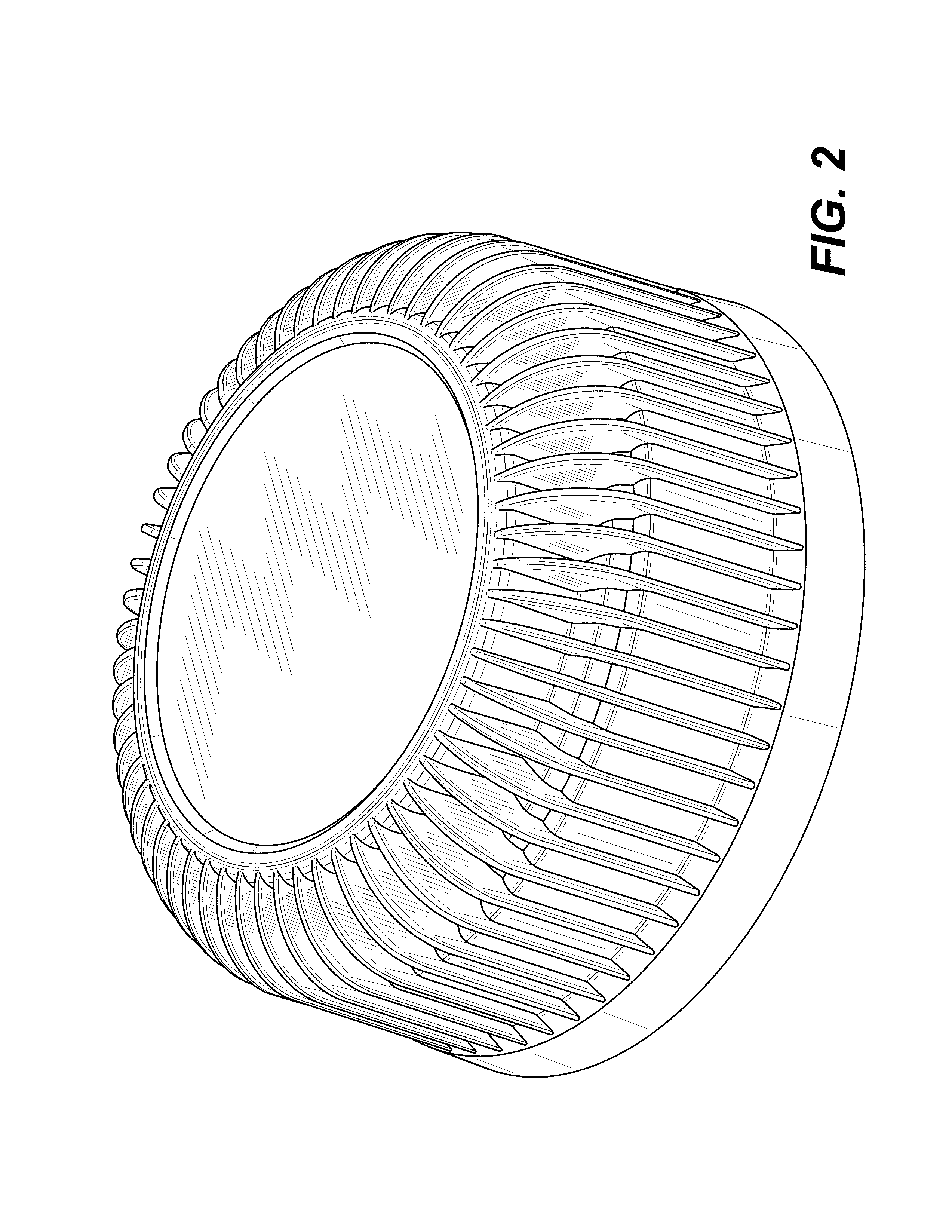
FIG. 2 is a second top, front perspective view thereof;
FIG. 3 is a top plan view thereof;
FIG. 4 is a bottom, front perspective view thereof;
FIG. 5 is a bottom plan view thereof;
FIG. 6 is a front elevation view thereof, with the rear elevation, left side, and right side views being identical thereto;
FIG. 7 is a top perspective cross-sectional view taken in the direction of line 7-7 shown in FIG. 3;
FIG. 8 is a top, front perspective view of a cap showing our new design in a second configuration before use;
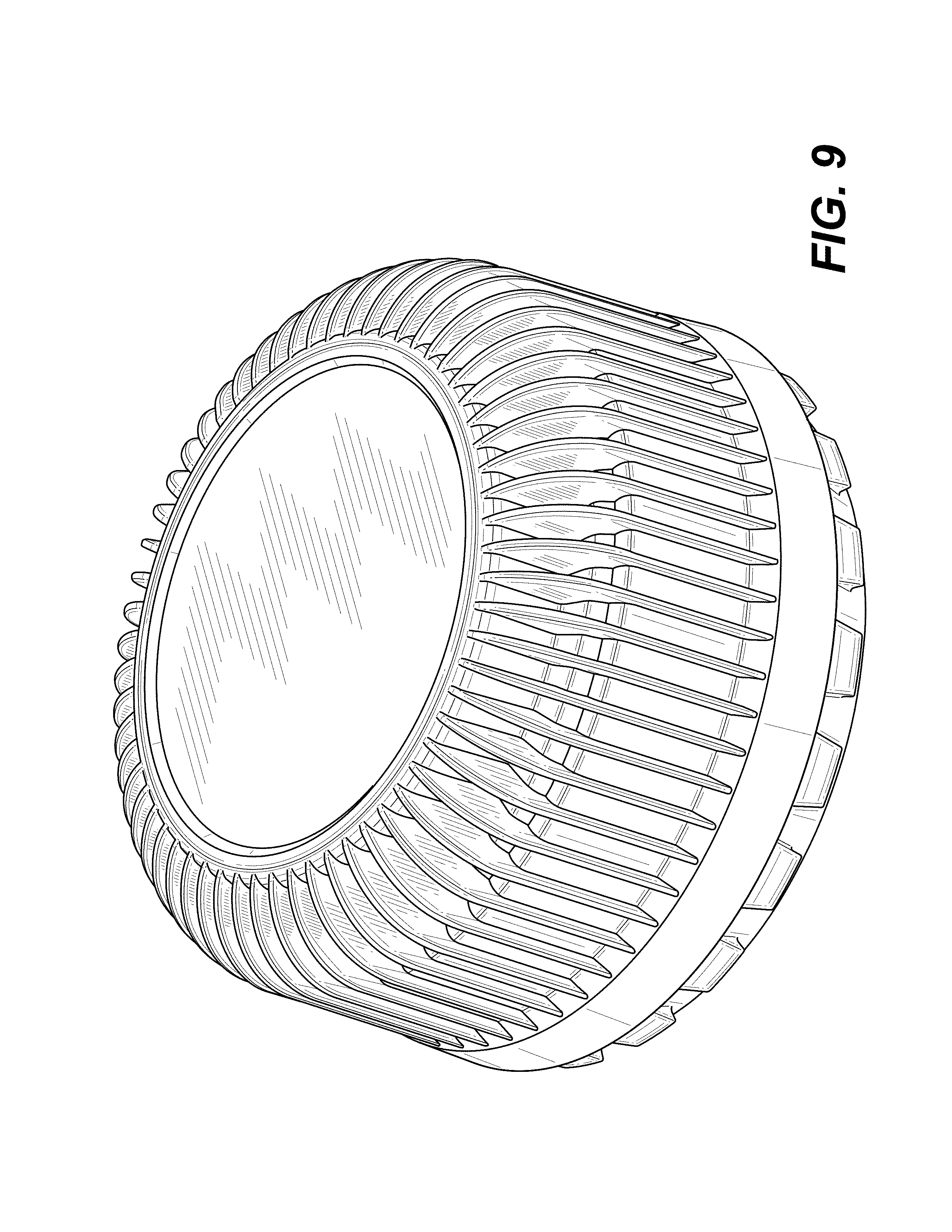
FIG. 9 is a second top, front perspective view thereof;
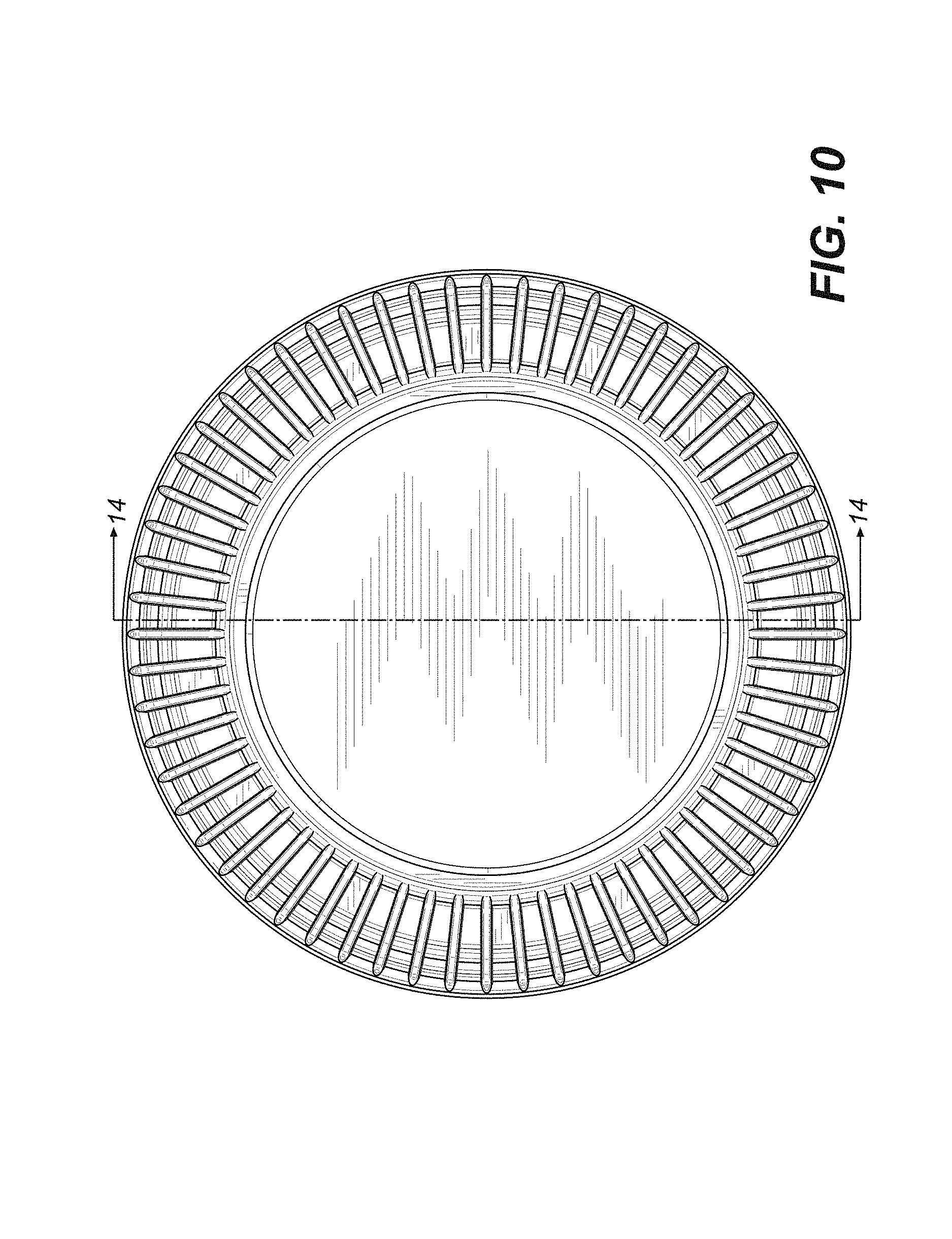
FIG. 10 is a top plan view thereof;
FIG. 11 is a bottom, front perspective view thereof;
FIG. 12 is a bottom plan view;
FIG. 13 is a front elevation view thereof, with the rear elevation, left side, and right side views being identical thereto; and,
FIG. 14 is a top perspective cross-sectional view taken in the direction of line 14-14 shown in FIG. 10.
* * * * *
D00000
D00001
D00002
D00003
D00004
D00005
D00006
D00007
D00008
D00009
D00010
D00011
D00012

D00013

D00014

XML
uspto.report is an independent third-party trademark research tool that is not affiliated, endorsed, or sponsored by the United States Patent and Trademark Office (USPTO) or any other governmental organization. The information provided by uspto.report is based on publicly available data at the time of writing and is intended for informational purposes only.
While we strive to provide accurate and up-to-date information, we do not guarantee the accuracy, completeness, reliability, or suitability of the information displayed on this site. The use of this site is at your own risk. Any reliance you place on such information is therefore strictly at your own risk.
All official trademark data, including owner information, should be verified by visiting the official USPTO website at www.uspto.gov. This site is not intended to replace professional legal advice and should not be used as a substitute for consulting with a legal professional who is knowledgeable about trademark law.