Ultrasonic probe
Naka , et al. J
U.S. patent number D837,391 [Application Number D/615,531] was granted by the patent office on 2019-01-01 for ultrasonic probe. This patent grant is currently assigned to NIHON DEMPA KOGYO CO., LTD.. The grantee listed for this patent is NIHON DEMPA KOGYO CO., LTD.. Invention is credited to Chao Li, Yoji Naka, Isamu Shimura, Takashi Wakabayashi.


| United States Patent | D837,391 |
| Naka , et al. | January 1, 2019 |
Ultrasonic probe
Claims
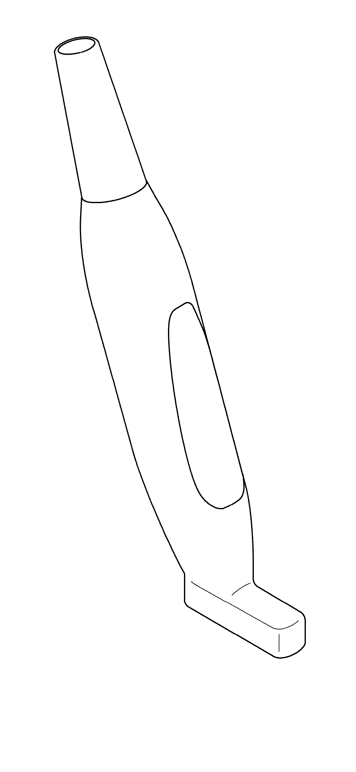
CLAIM The ornamental design for an ultrasonic probe, as shown and described.
| Inventors: | Naka; Yoji (Saitama, JP), Wakabayashi; Takashi (Saitama, JP), Shimura; Isamu (Saitama, JP), Li; Chao (Saitama, JP) | ||||||||||
|---|---|---|---|---|---|---|---|---|---|---|---|
| Applicant: |
|
||||||||||
| Assignee: | NIHON DEMPA KOGYO CO., LTD.
(Tokyo, JP) |
||||||||||
| Appl. No.: | D/615,531 | ||||||||||
| Filed: | August 30, 2017 |
Foreign Application Priority Data
| Apr 27, 2017 [JP] | 2017-009358 | |||
| Current U.S. Class: | D24/187 |
| Current International Class: | 2402 |
| Field of Search: | ;D24/186-187,144,200 ;D10/78 |
References Cited [Referenced By]
U.S. Patent Documents
| D343801 | February 1994 | Burns |
| D369307 | April 1996 | Imling |
| 5779639 | July 1998 | Yeung |
| D536450 | February 2007 | Ryan |
| D550365 | September 2007 | Kitayama |
| D623755 | September 2010 | Ikegame |
| 2015/0374331 | December 2015 | Cho |
| 304508902 | Feb 2018 | CN | |||
| 004154102-0001 | Aug 2017 | EP | |||
| 004154102-0002 | Aug 2017 | EP | |||
| 1095570 | Jan 2001 | JP | |||
| 1100193 | Feb 2001 | JP | |||
| 1593696 | Dec 2017 | JP | |||
| 1593697 | Dec 2017 | JP | |||
Assistant Examiner: Vansant; Calvin E
Attorney, Agent or Firm: JCIPRNET
Description
FIG. 1 is a perspective view of an ultrasonic probe showing our new design;
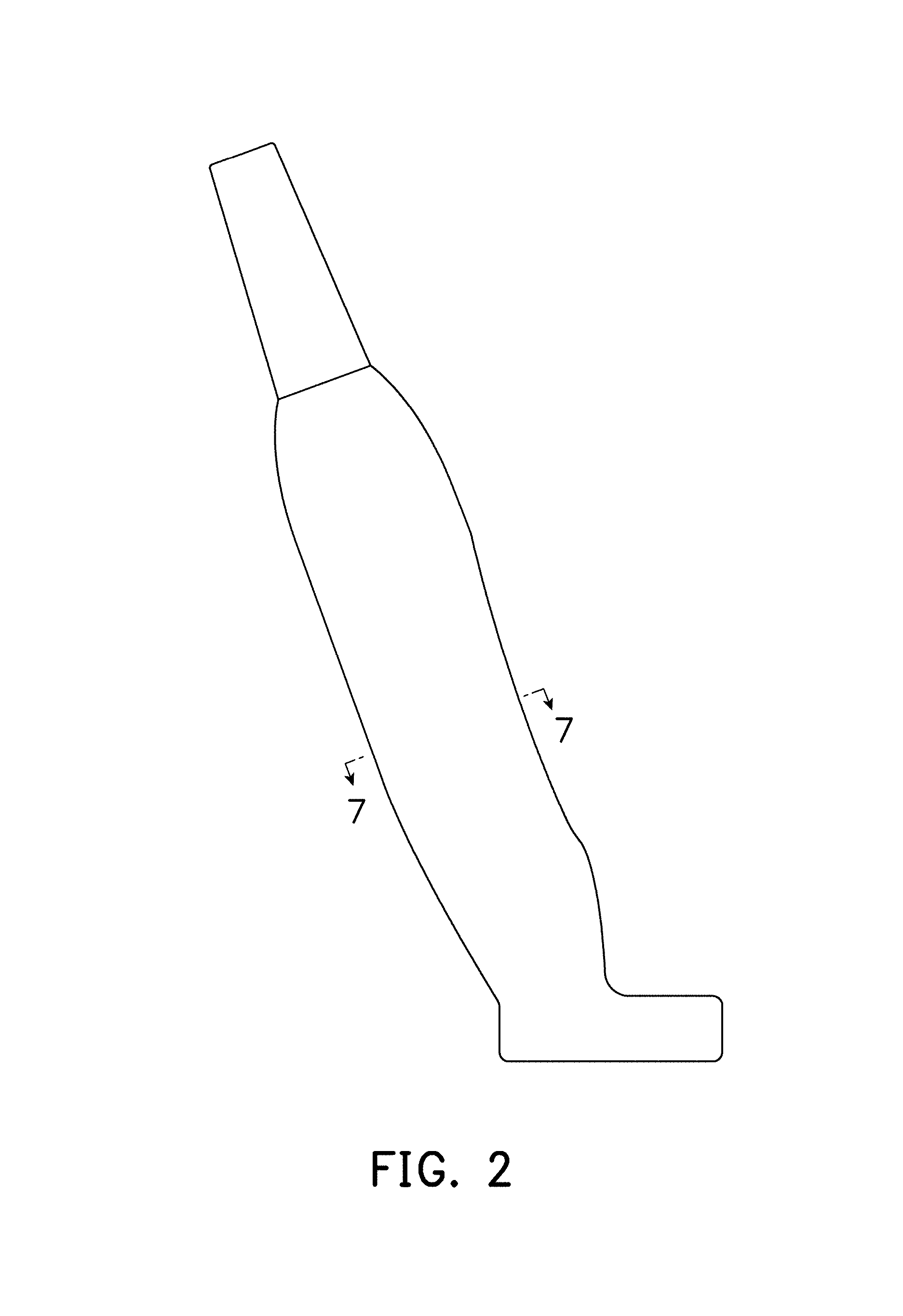
FIG. 2 is a front view with the rear view being a mirror image thereof;
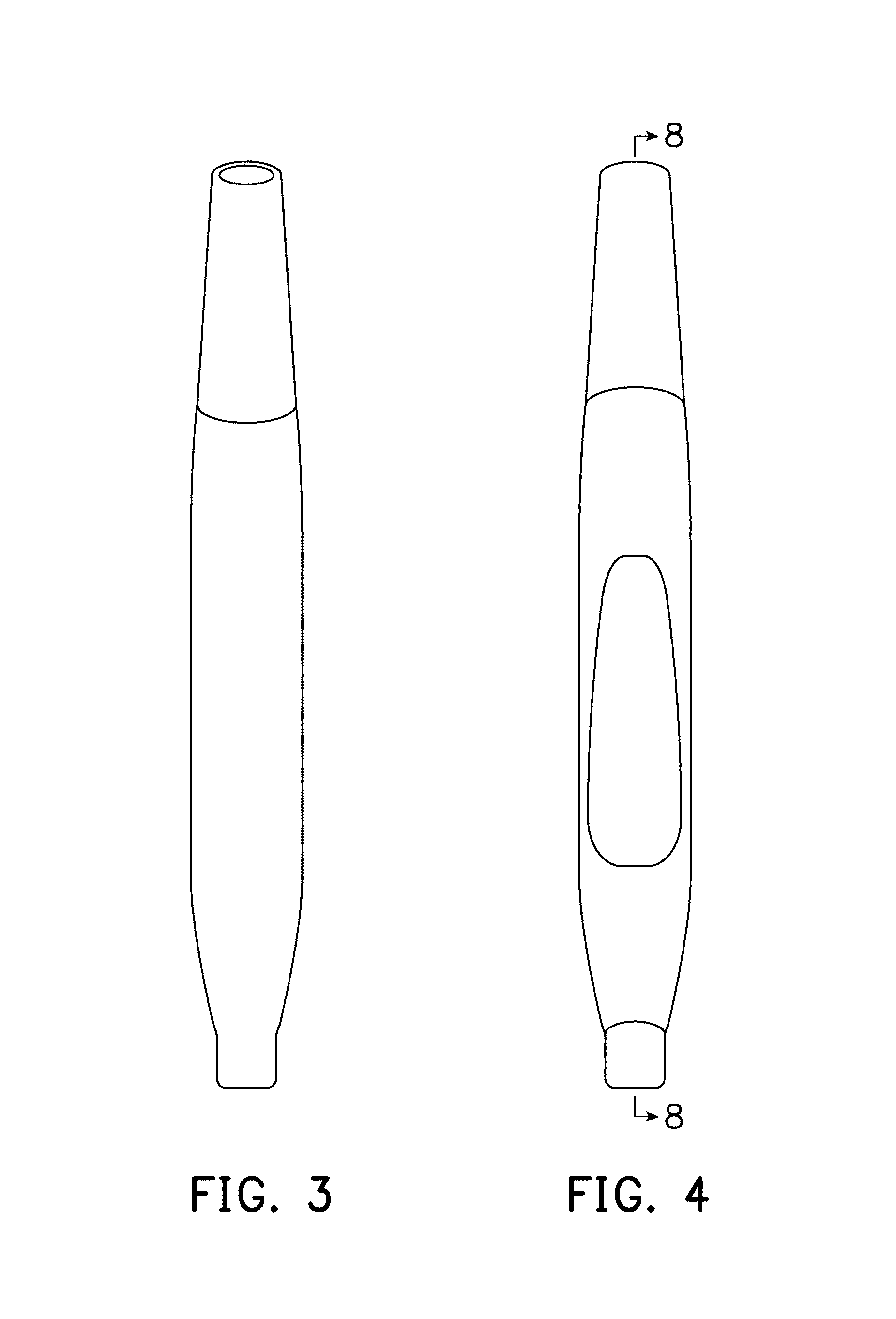
FIG. 3 is a left side view thereof;
FIG. 4 is a right side view thereof;
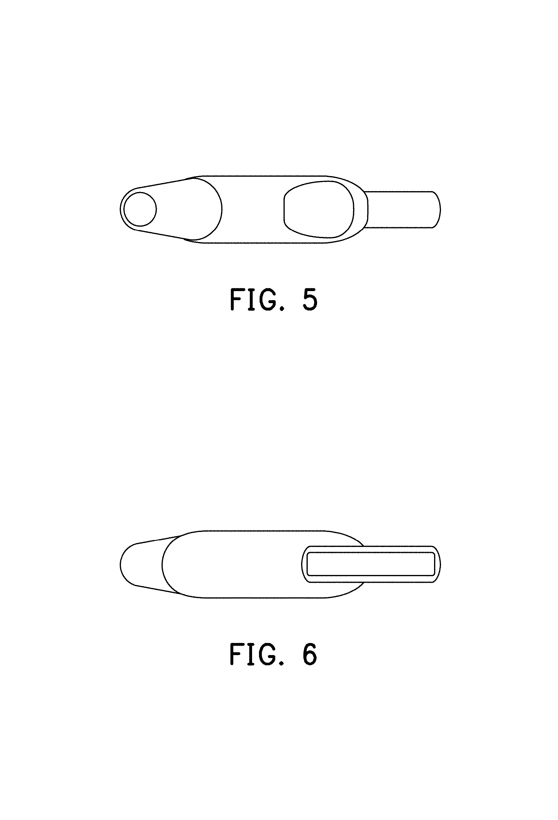
FIG. 5 is a top view thereof;
FIG. 6 is a bottom view thereof;
FIG. 7 is an enlarged end view of the cross-section thereof with the internal parts omitted, taken along the line 7-7 of FIG. 2;
FIG. 8 is a cross-section view thereof with the internal parts omitted, taken along the line 8-8 of FIG. 4; and,
FIG. 9 is a reference view thereof showing a user uses the ultrasonic probe of the claimed design.
The dot-dashed lines in FIG. 9 represent the environment of the claimed design in the use state and form no part thereof. The dashed broken lines depict portions of the ultrasonic probe and form no part of the claim.
* * * * *
D00000
D00001
D00002
D00003
D00004
D00005
D00006
D00007
XML
uspto.report is an independent third-party trademark research tool that is not affiliated, endorsed, or sponsored by the United States Patent and Trademark Office (USPTO) or any other governmental organization. The information provided by uspto.report is based on publicly available data at the time of writing and is intended for informational purposes only.
While we strive to provide accurate and up-to-date information, we do not guarantee the accuracy, completeness, reliability, or suitability of the information displayed on this site. The use of this site is at your own risk. Any reliance you place on such information is therefore strictly at your own risk.
All official trademark data, including owner information, should be verified by visiting the official USPTO website at www.uspto.gov. This site is not intended to replace professional legal advice and should not be used as a substitute for consulting with a legal professional who is knowledgeable about trademark law.